Anti-shaking device and crane

A crane and anti-sway technology, which is applied in the field of mechanical equipment, can solve problems such as installation difficulties, affecting maintenance operation space, and maintenance difficulties, and achieve stable and reliable working processes and good anti-sway effects

Pending Publication Date: 2019-09-27
SANY MARINE HEAVY IND
View PDF0 Cites 0 Cited by
  • Summary
  • Abstract
  • Description
  • Claims
  • Application Information

AI Technical Summary

Problems solved by technology

Electronic anti-shake collects information through various sensors and controls the operation of the car after analysis by the controller. It is passive anti-shake, and the anti-shake effect is poor.
[0003] When the existing cranes are anti-sway through the winding arrangement of steel wire ropes, most of them are divided into four-rope anti-sway and eight-rope anti-sway. The number of steel wire ropes is large and the winding is complicated, which is not only difficult to install, but also easily affects the maintenance operation space, making maintenance difficult

Method used


Image

  • Anti-shaking device and crane
  • Anti-shaking device and crane
  • Anti-shaking device and crane

Examples


Embodiment 1

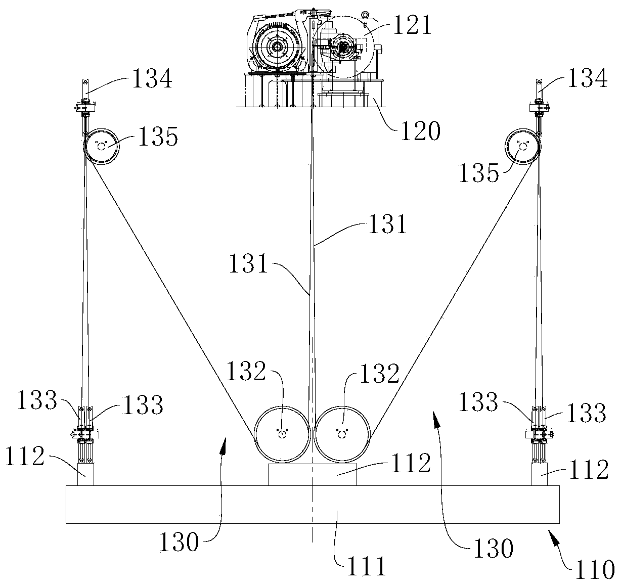
[0045] figure 1 A schematic structural diagram of the anti-sway device 100 provided in this embodiment. Please refer to figure 1 , the present embodiment provides an anti-sway device 100 , which includes a spreader 110 , a frame 120 , a reel 121 and an anti-sway assembly 130 , and the reel 121 is arranged on the frame 120 . The anti-sway assembly 130 includes a wire rope 131 , a first pulley 132 , a second pulley 133 and a third pulley 134 . Both the first pulley 132 and the second pulley 133 are arranged on the spreader 110 , and the third pulley 134 is arranged on the frame 120 . The two ends of wire rope 131 are respectively connected on frame 120 and reel 121, and wire rope 131 passes through first pulley 132, the 3rd pulley 134 and the second pulley 133 successively and winds up, thereby in the first pulley 132 and the 3rd pulley The plane where 134 is located and the plane where the third pulley 134 and the second pulley 133 are located all form an inverted triangle, ...

Embodiment 2

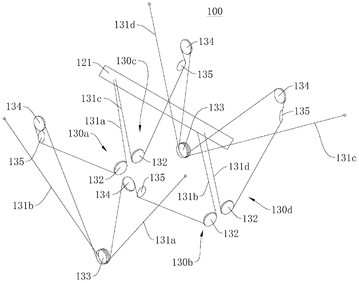
[0060] Figure 5 A schematic structural diagram of the anti-shake device 100 provided in this embodiment at a first viewing angle, Image 6 It is a schematic structural diagram of the anti-shake device 100 provided in this embodiment under a second viewing angle, Figure 7 A schematic diagram of a partial structure of the anti-shake device 100 in a third viewing angle provided in this embodiment. Please refer to Figure 5 to Figure 7, this embodiment also provides an anti-sway device 100, which is basically the same as the anti-sway device 100 provided in Embodiment 1, and the same parts will not be described again, except that the number of reels 121 is different.

[0061] Specifically, in this embodiment, the number of reels 121 is two, and the two reels 121 are arranged in the middle of the spreader body 111 along the width direction of the spreader body 111, and one of the reels 121 is arranged on the first anti- Between the sway assembly 130a and the third anti-sway as...

Embodiment 3

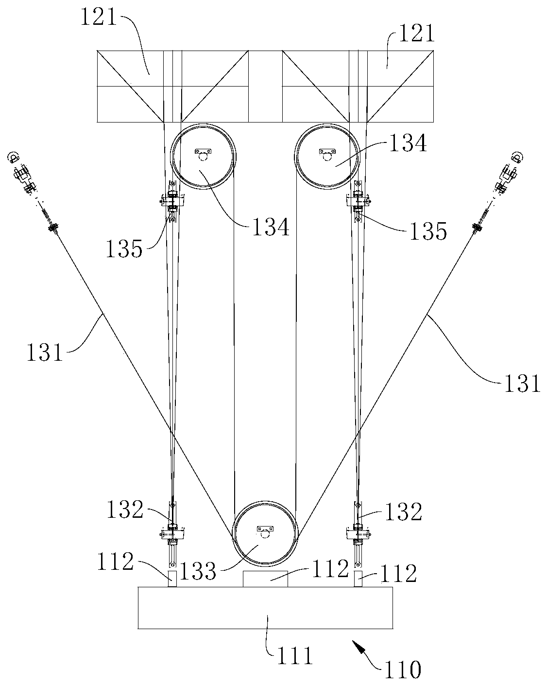
[0063] Figure 8 It is a schematic structural diagram of the anti-shake device 100 provided in this embodiment, Figure 9 A schematic structural diagram of the anti-shake device 100 provided in this embodiment at a first viewing angle, Figure 10 A schematic structural diagram of the anti-shake device 100 provided in this embodiment in a second viewing angle. Please refer to Figure 8 to Figure 10 , this embodiment also provides an anti-sway device 100, which is basically the same as the anti-sway device 100 provided in Embodiment 1, and the same parts will not be described again, except that the number of reels 121 is different.

[0064] Specifically, in this embodiment, the number of reels 121 is the same as the number of wire ropes 131, that is, the number of reels 121 is four, and the four wire ropes 131 are respectively connected to the four reels 121, and the four reels 121 are respectively located on the four corners of the spreader body 111, and the wire rope 131 wo...


PUM


Abstract

The embodiment of the invention provides an anti-shaking device and a crane, and relates to the technical field of mechanical equipment. The anti-shaking device comprises a lifting appliance, a rack, a winding drum and an anti-shaking component, the anti-shake assembly comprises a steel wire rope, a first pulley, a second pulley and a third pulley, the first pulley and the second pulley are both arranged on the hanger, the third pulley is arranged on the frame, the steel wire rope sequentially passes through the first pulley, the third pulley and the second pulley to be wound, so that the anti-pilling effect in the two planes can be realized at the same time, and the anti-pilling effect is good. The anti-shake assembly comprises a first anti-shake assembly and a second anti-shake assembly, and is specifically limited by the positions of pulleys of the two anti-shake assemblies, so that the interference of the steel wire ropes with different anti-shaking components in the using process is effectively avoided, and the working process is more stable and reliable.

Description

technical field [0001] The invention relates to the technical field of mechanical equipment, in particular to an anti-sway device and a crane. Background technique [0002] During the operation of traditional cranes, anti-sway devices need to be installed to suppress the swing of the spreader and the goods loaded on the spreader. The anti-sway devices are roughly divided into mechanical anti-sway and electronic anti-sway. Mechanical anti-sway is mostly carried out by winding arrangement of steel wire rope, which is mainly active anti-sway. Electronic anti-shake is achieved by collecting information from various sensors and controlling the operation of the car after analysis by the controller. It is passive anti-shake, and the anti-shake effect is poor. [0003] When the existing cranes are anti-sway through the winding arrangement of steel wire ropes, most of them are divided into four-rope anti-sway and eight-rope anti-sway. The number of steel wire ropes is large and the...

Claims


Application Information

Patent Timeline
IPC IPC(8): B66C13/06
CPCB66C13/06
Inventor 孙其峰邱少良刘成才
Owner SANY MARINE HEAVY IND
Why Eureka
Try Eureka