
Floater automatic control attack angle type T-shaped wing

A technology of float and angle of attack, which is applied in the direction of using hydrofoils to reduce the movement of ships on the surrounding water surface. It can solve the problems of poor anti-rolling effect, complicated technical structure, high cost, etc., and achieves convenient installation, obvious anti-rolling effect, and structural simple effect

Active Publication Date: 2017-02-22
DALIAN UNIV OF TECH
View PDF7 Cites 0 Cited by
  • Summary
  • Abstract
  • Description
  • Claims
  • Application Information

AI Technical Summary

Problems solved by technology

During the voyage of the passive T-wing, the angle of attack of the T-wing cannot be adjusted, and it can only passively withstand the angle of attack brought by the state of the ship, and the anti-rolling effect is poor; while the active T-wing can be flexibly adjusted through the navigation control system. Changing factors such as the angle of attack of the incoming current can improve the effect, but this control system has the disadvantages of complex technical structure and high cost. At the same time, the anti-rolling effect is not ideal due to the inability to adjust the angle of attack of the horizontal wing in a timely manner, which cannot meet the expectations of the ship. Airworthiness

Method used


Image

  • Floater automatic control attack angle type T-shaped wing
  • Floater automatic control attack angle type T-shaped wing
  • Floater automatic control attack angle type T-shaped wing

Examples


Embodiment Construction

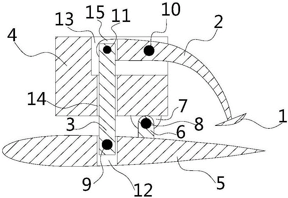
[0027] In order to make the purpose, technical solutions and advantages of the present invention clearer, the technical solutions of the present invention will be clearly and completely described below in conjunction with the accompanying drawings in the embodiments of the present invention. Obviously, the described embodiments are part of the implementation of the present invention. example, not all examples. Based on the embodiments of the present invention, all other embodiments obtained by persons of ordinary skill in the art without making creative efforts belong to the protection scope of the present invention.

[0028] The present invention has designed a kind of float automatic control angle-of-attack type T-shaped wing, the technical scheme of the present invention is further described below in conjunction with accompanying drawing and specific embodiment:

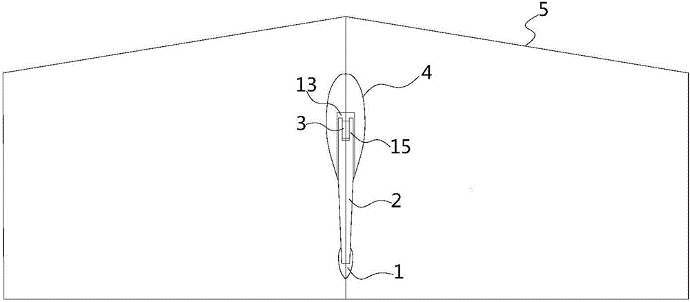
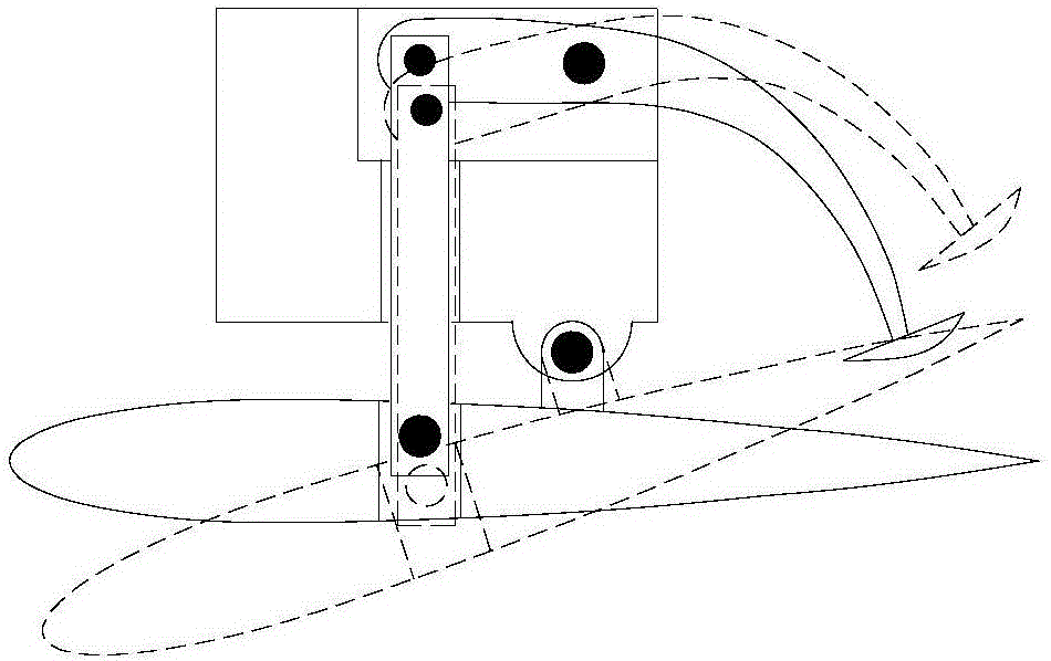
[0029] Such as figure 1 A float automatic control angle of attack type T-wing is shown, which is characterized...


PUM


Abstract

The invention discloses a floater automatic control attack angle type T-shaped wing. The floater automatic control attack angle type T-shaped wing is characterized by comprising a floater, a connecting rod, a pull rod, a vertical wing, a horizontal wing and a fixing shaft; a horizontal groove is formed in the upper end of the vertical wing, and a longitudinal columnar hollow structure communicated with the horizontal groove is arranged in the middle of the vertical wing; the connecting rod is partially placed in the horizontal groove and fixedly connected to the vertical wing; the connecting rod is connected with one end of the pull rod through the fixing shaft; the pull rod penetrates through the longitudinal columnar hollow structure on the vertical wing in the vertical direction, the bottom of the pull rod is inserted into a longitudinal groove in the horizontal wing in a matched mode, and the vertical wing and the horizontal wing are connected through a lifting lug in a matched mode; the end, stretching out of the horizontal groove, of the connecting rod is fixedly connected with the floater. The problems that due to the fact that the horizontal wing attack angle cannot be automatically controlled and adjusted, an existing T-shaped wing is poor in stabilization effect, complex in technology, high in cost and the like can be solved, and the floater automatic control attack angle type T-shaped wing is simple in structure, convenient to install, high in timeliness and remarkable in effect.

Description

technical field [0001] The invention relates to the technical field of ship design, in particular to a float automatic control angle of attack type T-shaped wing. Background technique [0002] With the rapid development of the shipping industry, the speed of ships is gradually increasing, and people have higher and higher requirements for travel comfort. As a simple structure and effective anti-rolling device, the T-shaped wing has been widely concerned. The T-shaped wing is a new type of anti-rolling attachment. Its main function is to improve the hydrodynamic performance of the ship, reduce the pitch and heave of the ship at high speed, and greatly improve the maneuverability and safety of the ship under extreme sea conditions. and comfort. [0003] At present, the T-wing can be divided into passive and active, and the anti-rolling effect of the active T-wing is more obvious than that of the passive T-wing. During the voyage of the passive T-wing, the angle of attack of...

Claims


Application Information

Patent Timeline
Patent Type & Authority Applications(China)
IPC IPC(8): B63B39/06
CPCB63B39/06
Inventor 宗智李娟潘宇邹丽
Owner DALIAN UNIV OF TECH
Learn More