
relay

A technology of relays and extensions, applied in the direction of relays, electromagnetic relays, detailed information of electromagnetic relays, etc., can solve the problem of contact pressure drop between contacts, and achieve the effect of suppressing contact pressure drop

Active Publication Date: 2021-06-04
ORMON CORP
View PDF7 Cites 0 Cited by
  • Summary
  • Abstract
  • Description
  • Claims
  • Application Information

AI Technical Summary

Problems solved by technology

Therefore, there is a possibility that the contact pressure between the contacts decreases

Method used


Image

  • relay
  • relay
  • relay

Examples


Embodiment Construction

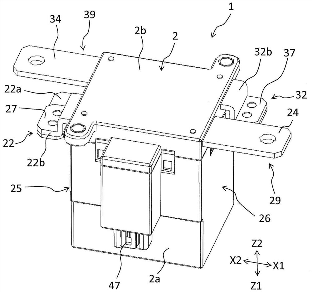
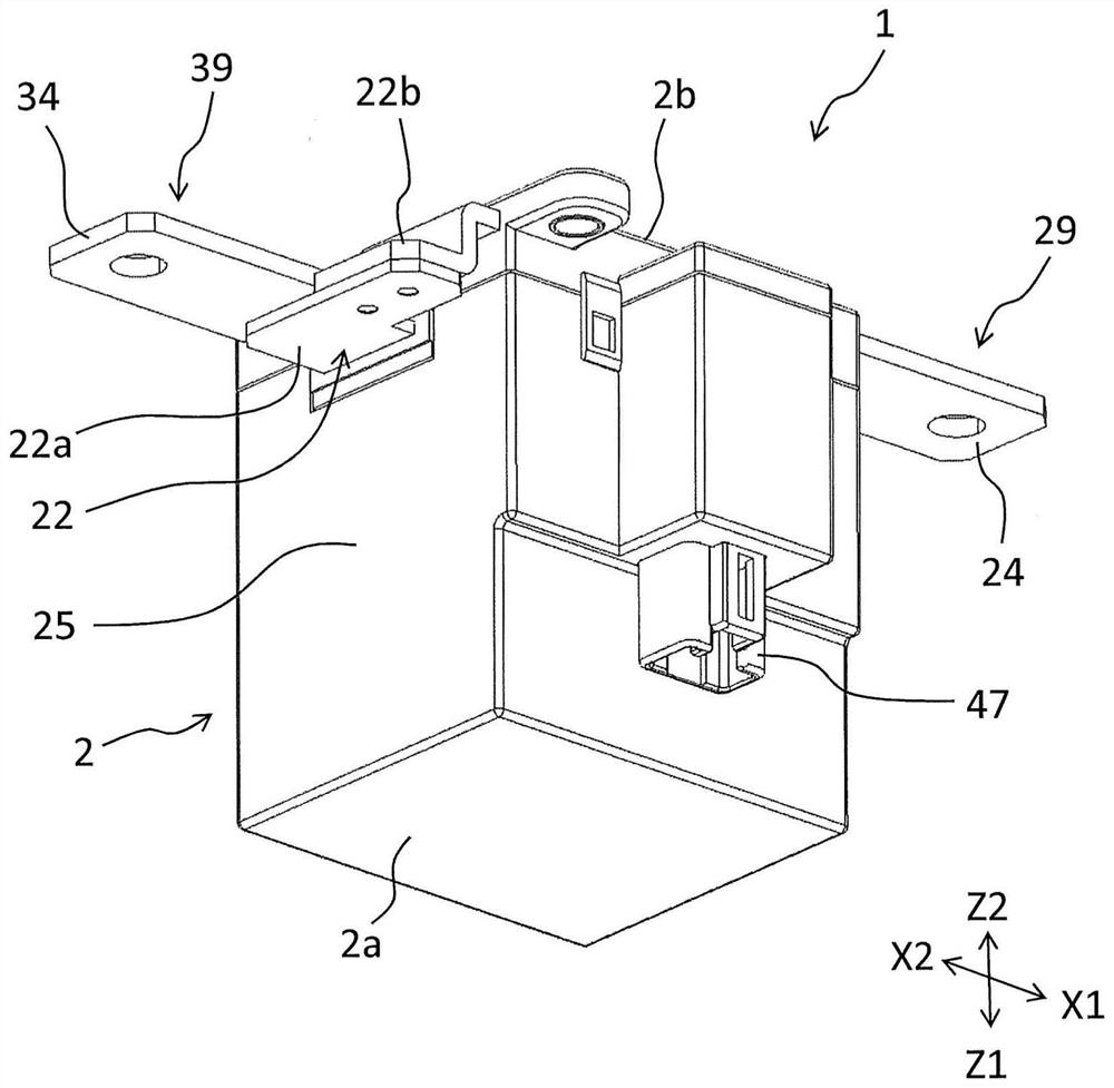
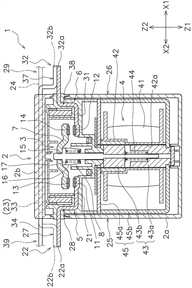
[0062] Next, relay 1 according to the embodiment will be described with reference to the drawings. figure 1 and figure 2 It is a perspective view which shows the relay 1 of embodiment. image 3 is a cross-sectional view of relay 1. Such as image 3 As shown, the relay 1 includes a housing 2 , a contact device 3 and a drive device 4 .

[0063] The housing 2 accommodates a contact device 3 and a drive device 4 . Case 2 is formed of insulating resin. The housing 2 includes a housing main body 2a and a cover portion 2b. The contact device 3 and the drive device 4 are arranged in the case main body 2a. The cover part 2b is separate from the case main body 2a. The cover part 2b is attached to the case main body 2a.

[0064] The contact device 3 includes a first fixed terminal 5 , a second fixed terminal 6 , a movable contact piece 7 and a contact piece holding portion 8 . The first fixed terminal 5, the second fixed terminal 6, and the movable contact piece 7 are formed o...


PUM


Abstract

A relay that suppresses drop in contact pressure between contacts. The first extension portion of the first fixed terminal extends in a first direction from the first movable contact toward the second movable contact. The first external connection portion of the first fixed terminal is connected to the first extension portion and protrudes from the housing in a first direction. The second extension of the second fixed terminal extends in a second direction from the second movable contact toward the first movable contact. The second external connection portion of the second fixed terminal is connected to the second extension portion and protrudes from the housing toward the second direction. Viewed from the moving direction of the movable contact piece, at least a part of the first extension part overlaps with the movable contact piece.

Description

technical field [0001] The present invention relates to relays. Background technique [0002] The relay has: a movable contact piece including a movable contact; and a fixed contact piece including a fixed contact. The movable contact piece moves, and the movable contact contacts or separates from the fixed contact, thereby opening and closing the contact. Here, the current flowing through the movable contact and the fixed contact causes the movable contact and the fixed contact to generate electromagnetic repulsion due to Lorentz force. This electromagnetic repulsion acts in a direction to separate the movable contact from the fixed contact. Therefore, when an overcurrent is energized, the electromagnetic repulsion is strong, and the contact pressure between the contacts may decrease. [0003] Therefore, conventionally, some relays have been provided with portions where currents flow to the movable contact piece and the fixed contact piece in opposite directions to gener...

Claims


Application Information

Patent Timeline
Patent Type & Authority Patents(China)
IPC IPC(8): H01H50/54H01H1/54
CPCH01H1/54H01H50/54H01H50/14H01H50/546H01H50/42H01H50/58H01H50/64H01H2205/002
Inventor 箕轮亮太岩坂博之林田靖雄森真吾川口直树
Owner ORMON CORP
Learn More