Efficient ceramic glazing device

A ceramic sealing and high-efficiency technology, used in ceramic molding machines, manufacturing tools, etc., can solve the problems of harming the health of operators, low production efficiency, and high labor intensity of manual glazing, and achieve the effect of ensuring physical health.

Active Publication Date: 2019-10-18
XUCHANG UNIV
View PDF7 Cites 4 Cited by
  • Summary
  • Abstract
  • Description
  • Claims
  • Application Information

AI Technical Summary

Problems solved by technology

[0004] In view of the above situation, in order to overcome the defects of the prior art, the present invention provides a high-efficiency ceramic glaze sealing device, which effectively solves the problems of high labor intensity and low production efficiency of manual glazing, as well as the very complicated and inconvenient manual glazing. At the same time, manual glazing will seriously endanger the health of workers

Method used


Image

  • Efficient ceramic glazing device
  • Efficient ceramic glazing device
  • Efficient ceramic glazing device

Examples


Embodiment 1

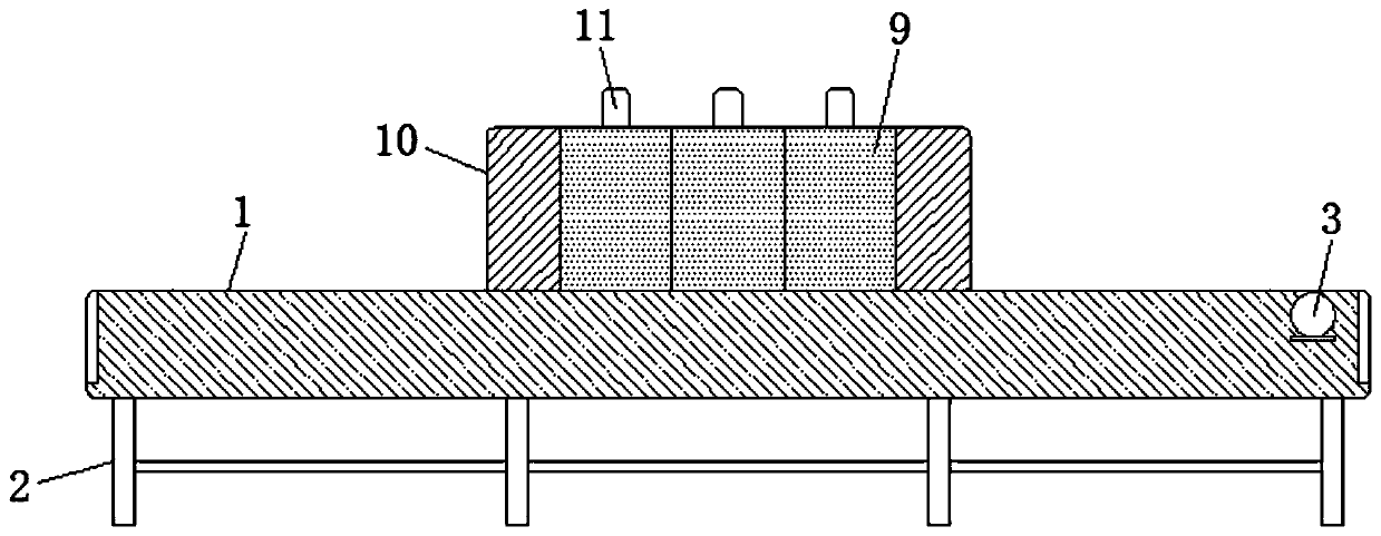
[0029] Embodiment one, by figure 1 , figure 2 , image 3 , Figure 4 and Figure 5 Provided, the present invention includes a transmission trough 1, the bottom of the transmission trough 1 is fixedly installed with a support leg 2, and one end of the surface of the transmission trough 1 is fixedly installed with a first motor 3, and through the setting of the first motor 3, it is possible to give the transmission Mechanism 4 provides power for transmission. Transmission mechanism 4 is installed inside transmission slot plate 1. Three rotating mechanisms 5 are installed in the middle of transmission mechanism 4. Fixed mechanism 6 is installed in the middle of three rotating mechanisms 5. Three rotating mechanisms 5 The both sides of top are all provided with ceramic embryo body 7, are all provided with to hold clamping mechanism 8 between the top of two ceramic embryo bodies 7 and the both sides of fixing mechanism 6 tops, the middle part of transmission groove plate 1 top ...

Embodiment 2

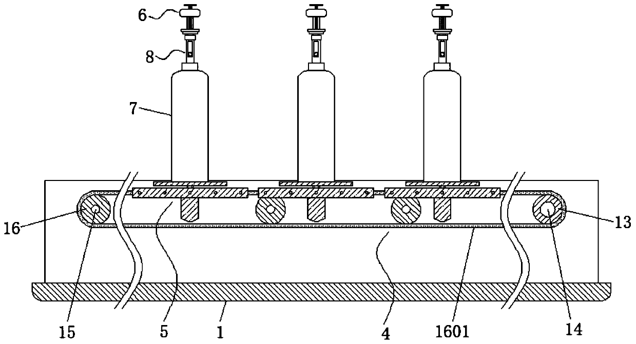
[0030] Embodiment two, on the basis of embodiment one, by figure 2Given, the transmission mechanism 4 includes a main shaft 13, a main gear 14, a counter shaft 15, a sub gear 16 and a chain 1601, the main shaft 13 is movably installed at one end inside the transmission slot plate 1, and one end of the main shaft 13 is connected to the output of the first motor 3 The main gear 14 is fixedly connected to the two ends of the main shaft 13, the auxiliary shaft 15 is equidistantly installed inside the transmission slot plate 1, the auxiliary gear 16 is fixedly connected to the two ends of the auxiliary shaft 15, and the main gear at the two ends of the main shaft 13 A chain 1601 is connected between the gear 14 and the pinion gear 16 at the two ends of the countershaft 15. Through the arrangement of the main shaft 13, the main gear 14, the countershaft 15, the pinion gear 16 and the chain 1601, it can effectively clean the ceramic body. 7 for transmission.

Embodiment 3

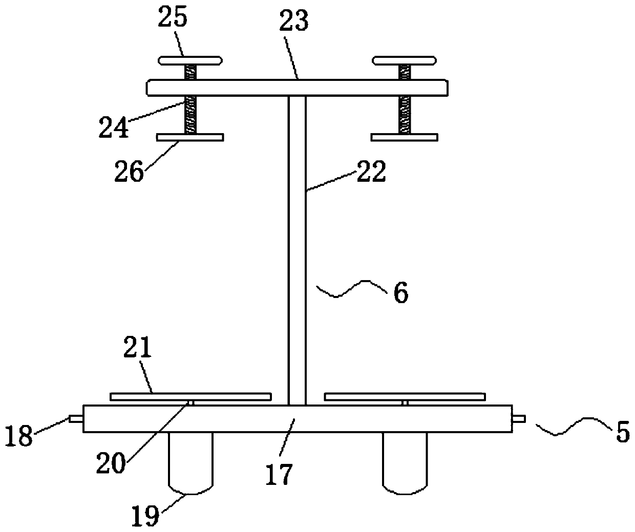
[0031] Embodiment three, on the basis of embodiment one, by image 3 Given, the three rotating mechanisms 5 all include a bottom plate 17, a connecting shaft 18, a third motor 19, a rotating shaft 20 and a placement plate 21, and the two sides of the three bottom plates 17 are fixedly connected to two chains 1601 through the connecting shaft 18 at equal distances. , the third motor 19 is fixedly installed on both sides of the bottom of the base plate 17, the rotating shafts 20 are respectively fixedly connected to the output ends of the two third motors 19, and one end of the two rotating shafts 20 extends to the top of the base plate 17 and is respectively connected to the placement plate 21 The stationary phase is connected, and through the setting of the bottom plate 17, the connecting shaft 18, the third motor 19, the rotating shaft 20 and the placement plate 21, it can drive a plurality of ceramic embryos 7 to rotate.


PUM


Abstract

The invention relates to the technical field of ceramic glazing devices, discloses an efficient ceramic glazing device, and solves the problems that the existing manual glazing is high in labor intensity, low in production efficiency, complex and inconvenient, and seriously damages the body health of operators. The efficient ceramic glazing device comprises a conveying groove plate, wherein supporting legs are fixedly arranged at the bottom of the conveying groove plate, a first motor is fixedly arranged at one end of the surface of the conveying groove plate, a conveying mechanism is arrangedinside the conveying groove plate, three rotating mechanisms are arranged in the middle of the conveying mechanism, the middle parts of the three rotating mechanisms are provided with fixing mechanisms correspondingly, and two sides of the top of each of the three rotating mechanisms are provided with ceramic blanks correspondingly. According to the efficient ceramic glazing device, the efficientglazing can be carried out on the blank during use, and the glazing process is simple, convenient, stable and effective; and meanwhile, the blank is not in contact with the operators during glazing,so that the body health of the operators is guaranteed.

Description

technical field [0001] The invention belongs to the technical field of ceramic glaze sealing devices, in particular to a high-efficiency ceramic glaze sealing device. Background technique [0002] Ceramic products have become indispensable utensils in people's lives. The surface of ceramic products is generally covered with a thin layer of glazed substance, which is called glaze. Glaze has the properties of bright, translucent, smooth and impermeable. The glazed ceramics have glass luster after firing, which can beautify the appearance of the ceramics, and the glaze can reduce the water absorption of the ceramics and prolong the service life of the ceramics. [0003] The traditional method of glazing ceramic products is manual glazing with spray guns. This method makes the labor intensity of the workers high, the production efficiency is low, and it cannot be produced in large quantities. At the same time, manual glazing needs to be repeated up and down and left and right. ...

Claims


Application Information

Patent Timeline
Patent Type & Authority Applications(China)
IPC IPC(8): B28B11/04
CPCB28B11/044B28B11/048
Inventor 李维维
Owner XUCHANG UNIV
Why Eureka
Try Eureka