Submarine cable fault location system and method based on optical fiber pulse transmission

A technology of pulse transmission and fault location, which can be used in the detection of faults, fault locations, and fault detection by conductor type using the pulse reflection method. , to achieve high-precision fault location and solve the effect of testing blind spots

Active Publication Date: 2021-08-03
GUANGDONG POWER GRID CO LTD +1
View PDF5 Cites 0 Cited by
  • Summary
  • Abstract
  • Description
  • Claims
  • Application Information

AI Technical Summary

Problems solved by technology

[0003] At present, the status monitoring of submarine cables is mainly for circulation and temperature measurement, which can only detect the circulation and temperature of the cable operating state, but cannot give early warning of fault locations; submarine disturbance monitoring can give early warning of fault locations, but due to poor signal pattern recognition processing, resistance to The interference is poor, resulting in a high false alarm rate of disturbance monitoring, which causes great interference to maintenance work; there are distributed installations of traveling wave ranging terminals on transmission lines, and a terminal is installed every 10 to 20km to collect fault current traveling waves and apply GPS time synchronization, transmits signals to the main station through the 4G network, and judges the fault distance through the main station. The time resolution is more than a few microseconds, and the ranging error is more than a few hundred meters to several thousand meters. The test accuracy is low and the cost is high. However, some high-voltage cable terminals stand underground, and the signal shielding cannot receive GPS signals at all, which makes this method unusable; there is a Chinese patent CN201210297818.5 that connects the first terminal and the second terminal to measure distance through optical fibers, and the resolution is at the nanosecond level. It can meet the precision requirements, but designing a high-resolution synchronous clock is technically difficult and costly and difficult to promote

Method used


Image

  • Submarine cable fault location system and method based on optical fiber pulse transmission
  • Submarine cable fault location system and method based on optical fiber pulse transmission
  • Submarine cable fault location system and method based on optical fiber pulse transmission

Examples


Embodiment 1

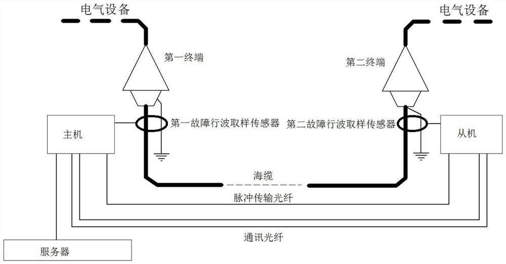
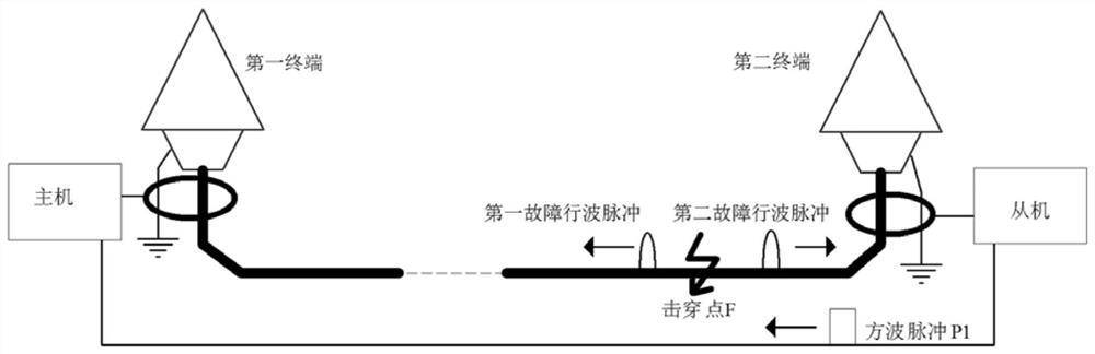
[0047] Such as Figure 1 to Figure 4 Shown is an embodiment of the submarine cable fault location system based on optical fiber pulse transmission of the present invention, the two ends of the submarine cable are respectively provided with a first terminal and a second terminal connected to electrical equipment, and the first terminal passes through the second terminal. A grounding wire is grounded, and the second terminal is grounded through the second grounding wire; the submarine cable is connected to the host near the first terminal and the first grounding wire, and the submarine cable is connected to the second terminal and the second grounding A slave is connected with a line, the master is connected with a server, the master and the slave communicate through a communication optical fiber, and the master and the slave are connected with a pulse transmission optical fiber for sending square wave pulses to the master; when the submarine cable exists When the breakdown poin...

Embodiment 2

[0063] Such as Figure 5 to Figure 6 Shown is the embodiment of the submarine cable fault location method based on optical fiber pulse transmission of the present invention, comprises the following steps:

[0064] S10. When a breakdown point F appears on the submarine cable, the first fault traveling wave pulse is generated at the breakdown point F to be transmitted to the master, and the second fault traveling wave pulse is generated to be transmitted to the slave;

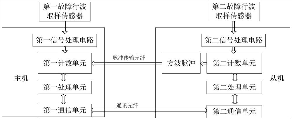
[0065] S20. The time when the host receives the first fault traveling wave pulse in step S10 is recorded as the first moment T 1 , while the slave machine receives the second fault traveling wave pulse described in step S10, and generates a square wave pulse;

[0066] S30. The square wave pulse described in step S20 is transmitted to the host through the pulse transmission fiber, and the host receives the square wave pulse after a delay of T D The postscript is the second moment T 2 ;

[0067] S40. According ...


PUM


Abstract

The present invention relates to the technical field of power cable monitoring, and more specifically, to a submarine cable fault ranging system and method based on optical fiber pulse transmission. and the second grounding wire are connected to the slave, the master is connected to the server, the master and the slave communicate through the communication optical fiber, and the master and the slave are connected with a pulse transmission fiber for sending square wave pulses to the master; when the submarine cable strikes When passing through, the breakdown point generates the first fault traveling wave pulse to transmit to the master, the second fault traveling wave pulse to the slave, the slave detects the second fault traveling wave pulse and sends a square wave pulse, and the square wave pulse passes through the pulse transmission fiber transmitted to the host. The main engine of the present invention realizes online ranging according to the time difference between the detected first fault traveling wave pulse and the square wave pulse, and delays the square wave pulse detected by the main engine, which solves the blind area of ​​system testing and realizes the full range of the submarine cable. Long-range and high-precision fault location.

Description

technical field [0001] The invention relates to the technical field of power cable monitoring, and more particularly, to a submarine cable fault distance measurement system and method based on optical fiber pulse transmission. Background technique [0002] Submarine cables are an important part of the construction of cross-sea networking projects, and play an important role in realizing the internationalization of power grids and the interconnection of regional power grids. In recent years, with the improvement of the economic level, the demand for electric energy on islands and land is increasing. Many areas of the national power grid have been constructed and a large number of submarine cables and offshore wind power are under construction. In terms of submarine cable operation and maintenance, problems are more prominent due to the lack of relevant technical standards and instruments and equipment in the high-precision monitoring and testing of submarine cables, as well a...

Claims


Application Information

Patent Timeline
Patent Type & Authority Patents(China)
IPC IPC(8): G01R31/08G01R31/11
CPCG01R31/083G01R31/11
Inventor 孙廷玺王升孔德武黄毓华郑柒拾崔江静李莹雷小月李辰仇炜
Owner GUANGDONG POWER GRID CO LTD
Why Eureka
Try Eureka