Submarine cable fault ranging system and method based on optical fiber pulse transmission
A technology of pulse transmission and fault distance measurement, which is applied in the direction of fault detection, fault location, and fault detection according to conductor type by using pulse reflection method, which can solve problems such as low test accuracy, high technical difficulty and cost, difficulty in popularization, and maintenance work interference. , to achieve high-precision fault location and solve the effect of blind spots in system testing
- Summary
- Abstract
- Description
- Claims
- Application Information
AI Technical Summary
Problems solved by technology
Method used
Image
Examples
Embodiment 1
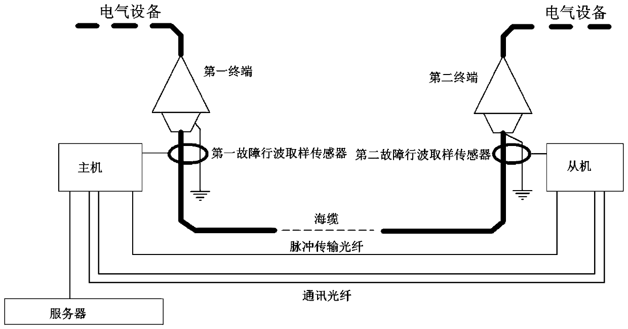
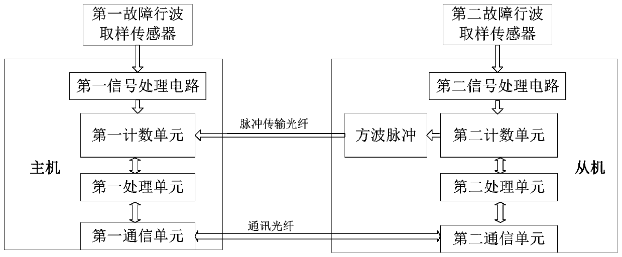
[0047] like Figure 1 to Figure 4 Shown is an embodiment of the submarine cable fault location system based on optical fiber pulse transmission of the present invention, the two ends of the submarine cable are respectively provided with a first terminal and a second terminal connected to electrical equipment, and the first terminal passes through the second terminal. A grounding wire is grounded, and the second terminal is grounded through the second grounding wire; the submarine cable is connected to the host near the first terminal and the first grounding wire, and the submarine cable is connected to the second terminal and the second grounding A slave is connected with a line, the master is connected with a server, the master and the slave communicate through a communication optical fiber, and the master and the slave are connected with a pulse transmission optical fiber for sending square wave pulses to the master; when the submarine cable exists When the breakdown point o...
Embodiment 2
[0063] like Figure 5 to Figure 6 Shown is the embodiment of the submarine cable fault location method based on optical fiber pulse transmission of the present invention, comprises the following steps:
[0064] S10. When a breakdown point F appears on the submarine cable, the first fault traveling wave pulse is generated at the breakdown point F to be transmitted to the master, and the second fault traveling wave pulse is generated to be transmitted to the slave;
[0065] S20. The time when the host receives the first fault traveling wave pulse in step S10 is recorded as the first moment T 1 , while the slave machine receives the second fault traveling wave pulse described in step S10, and generates a square wave pulse;
[0066] S30. The square wave pulse described in step S20 is transmitted to the host through the pulse transmission fiber, and the host receives the square wave pulse after a delay of T D The postscript is the second moment T 2 ;
[0067] S40. According to ...
PUM
 Abstract
Description
Claims
Application Information
 - R&D
- Intellectual Property
- Life Sciences
- Materials
- Tech Scout
- Unparalleled Data Quality
- Higher Quality Content
- 60% Fewer Hallucinations
Browse by: Latest US Patents, China's latest patents, Technical Efficacy Thesaurus, Application Domain, Technology Topic, Popular Technical Reports.
© 2025 PatSnap. All rights reserved.Legal|Privacy policy|Modern Slavery Act Transparency Statement|Sitemap|About US| Contact US: help@patsnap.com


