Pressure wire welding device, welding equipment and control method

A technology of welding equipment and control method, which is applied in the field of photovoltaic equipment, can solve the problems of welding failure, easy collapse of welding strips, virtual welding, etc., and achieves the effect of firm welding

Pending Publication Date: 2019-10-22
LUOYANG CSI PHOTOVOLTAIC TECH CO LTD
View PDF0 Cites 0 Cited by
  • Summary
  • Abstract
  • Description
  • Claims
  • Application Information

AI Technical Summary

Problems solved by technology

Since the welding rod is only lapped on the bus bar 6' before the welding head is pressed down, the welding head can easily drive the welding ribbon 5' on the side of the bus bar 6' to move during the pressing of the welding head, causing the welding ribbon 5' to move. Problems such as arching and cell 4' damage
And in the process of lifting the welding head to the cold pressure block after the welding head is melted, there is no pressure-holding measure for the welding strip 5' and the bus bar 6', and the welding strip 5' and the bus bar 6' are easy to break apart, resulting in a false weld. Thus affecting the welding quality, and even lead to welding failure

Method used


Image

  • Pressure wire welding device, welding equipment and control method
  • Pressure wire welding device, welding equipment and control method
  • Pressure wire welding device, welding equipment and control method

Examples


Embodiment Construction

[0036] In order to make the technical problems solved by the present invention, the technical solutions adopted and the technical effects achieved clearer, the technical solutions of the present invention will be further described below in conjunction with the accompanying drawings and through specific implementation methods.

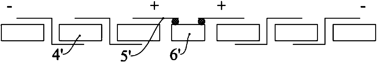
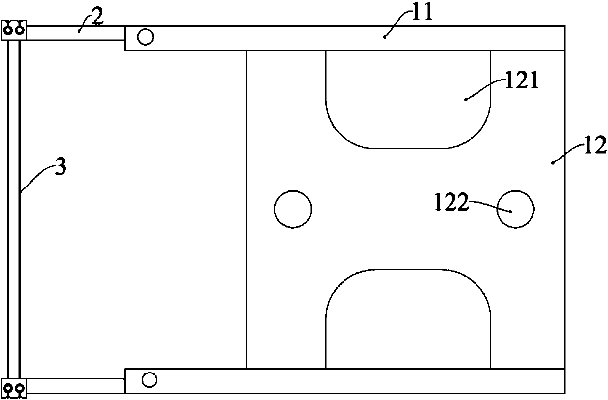
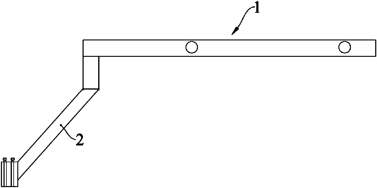
[0037] This embodiment provides a welding device that can be used for welding ribbons and bus bars in a photovoltaic module. The welding equipment includes a welding head, a cold briquetting block and a driving mechanism. The driving mechanism is respectively connected with the welding head and the cold briquetting block, and can drive the welding head and the cold briquetting block to lift or press down, so as to realize heating, melting and cooling and holding pressure.

[0038] In order to ensure that the welding strip and the bus bar are always in a compressed state, thereby improving the welding quality, the welding equipment in this embodiment is a...


PUM


Abstract

The invention discloses a pressure wire welding device, welding equipment and a control method and relates to the technical field of photovoltaic devices. The pressure wire welding device comprises amounting bracket, supporting arms and pressure wires. The two supporting arms are arranged at one end of the mounting bracket at an interval. The two sets of pressure wires are arranged in parallel between the two supporting arms, two ends of each set of pressure wires are correspondingly connected with the two supporting arms, and the distance between the two sets of pressure wires is not less than the width of a bus bar. By arranging the two sets of parallel pressure wires, the two sets of pressure wires can be correspondingly located on both sides of the bus bar before welding and abut against welding strips in overlap joint with the bus bar, so that the holding force is provided for attachment of the welding strips and the bus bar, and the problems such as bending of the welding stripsand damage of battery pieces caused by the movement of the welding strips during the pressing process of welding heads are avoided. During the welding process, the two sets of pressure wires are always located on both sides of the bus bar; the welding heads and cold press blocks can be pressed and lifted normally, and the pressure wires are continuously pressed, so that the steady and reliable welding of the welding strips and the bus bar can be ensured, and the welding is firm.

Description

technical field [0001] The invention relates to the technical field of photovoltaic equipment, in particular to a welding pressing wire device, welding equipment and a control method. Background technique [0002] As the energy crisis and environmental problems such as smog and greenhouse effect become more and more serious, energy transformation is imminent. Due to the advantages of clean, pollution-free and large reserves of photovoltaic energy, the photovoltaic industry has received strong support from governments of various countries, has made great progress in technology, and has been more and more widely used. Solar energy has become one of the most promising new energy sources today. . [0003] Photovoltaic modules are formed by welding and laminating a large number of photovoltaic cells. Photovoltaic modules need to connect multiple cells in series through ribbons to form a module, then weld the ribbons of the module to the bus bars, and finally laminate them throu...

Claims


Application Information

Patent Timeline
Patent Type & Authority Applications(China)
IPC IPC(8): B23K37/00
CPCB23K37/00
Inventor 董保东程向南李飞龙毛霄霄
Owner LUOYANG CSI PHOTOVOLTAIC TECH CO LTD
Why Eureka
Try Eureka