A kind of railway freight auxiliary device
An auxiliary device, a technology for railway freight transportation, which is applied in the field of railway freight transportation, can solve the problems of low work efficiency and inconvenient cargo distribution, etc., and achieve the effect of improving work efficiency
- Summary
- Abstract
- Description
- Claims
- Application Information
AI Technical Summary
Problems solved by technology
Method used
Image
Examples
specific Embodiment approach 1
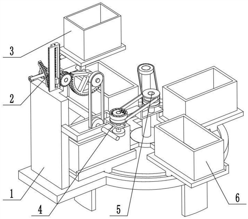
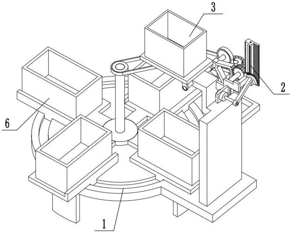
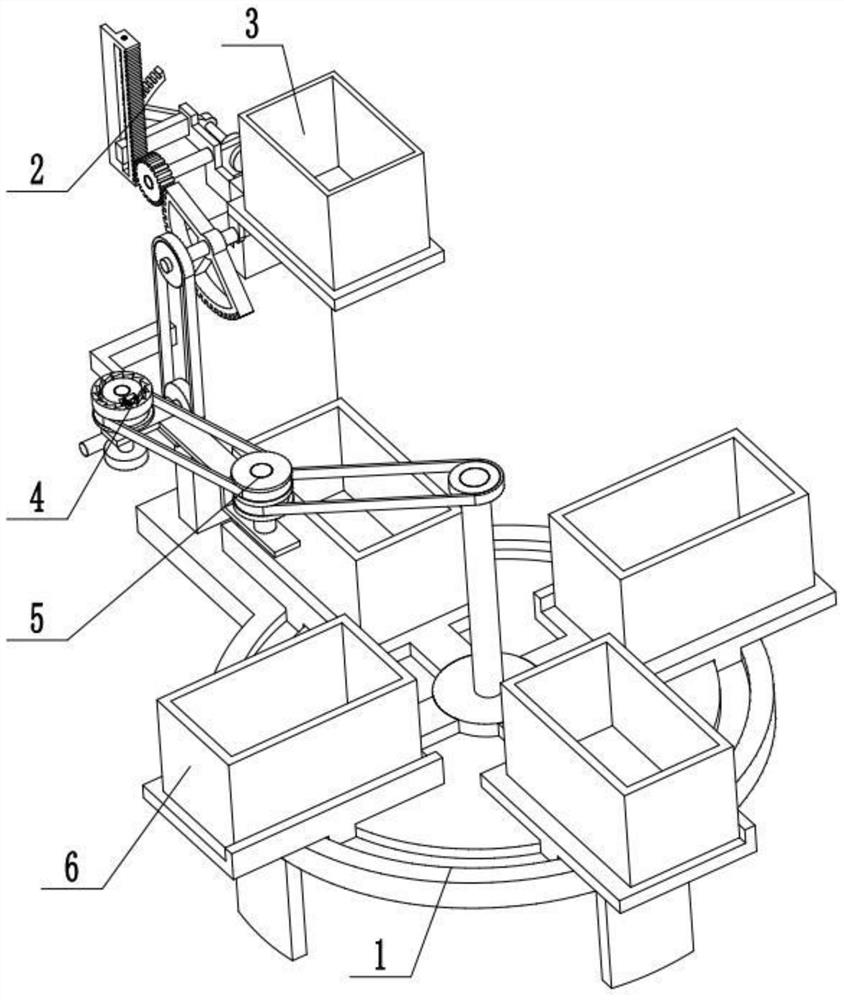
[0031] Combine below Figure 1-12Describe this embodiment, a railway freight auxiliary device, including a frame 1, an overturning control mechanism 2, an overturning box assembly 3, an intermittent rotation control mechanism 4, a power transmission mechanism 5, and an operation box assembly 6. The overturning control mechanism 2 Set on the upper end of the frame 1, the turning box assembly 3 is rotatably connected to the upper end of the frame 1, the turning control mechanism 2 is meshed with the turning box assembly 3, and the intermittent rotation control mechanism 4 is fixedly connected to the middle of the frame 1, intermittently rotating The control mechanism 4 is connected to the turning box assembly 3 through a belt transmission, the power transmission mechanism 5 is fixedly connected to the intermittent rotation control mechanism 4, the power transmission mechanism 5 is connected to the intermittent rotation control mechanism 4 through a belt transmission, and the oper...
specific Embodiment approach 2
[0033] Combine below Figure 1-12 To illustrate this embodiment, the frame 1 includes a base 1-1, a support foot 1-2, an annular groove 1-3, a flipping box swivel seat 1-4 and a support plate 1-5; the lower end of the base 1-1 surrounds The four supporting feet 1-2 are fixedly connected, the right end of the base 1-1 is provided with an annular groove 1-3, and the turning base 1-4 of the turning box is fixedly connected to the left end of the base 1-1 through the supporting plate 1-5.
specific Embodiment approach 3
[0035] Combine below Figure 1-12 To illustrate this embodiment, the flip control mechanism 2 includes a motor 2-1, a pedestal plate 2-2, a rotating rod 2-3, an arc-shaped rack 2-4, a rack I 2-5, and a rack II 2-6 , spring sleeve rod 2-7, compression spring I 2-8, limit plate 2-9, gear 2-10 and gear rotating shaft 2-11; motor 2-1 is fixedly connected on the shaft frame plate 2-2 through the motor frame, The shaft frame plate 2-2 is fixedly connected to the support plate 1-5, the output shaft of the motor 2-1 is fixedly connected to the rotating rod 2-3, and the rotating rod 2-3 is fixedly connected to the arc rack 2-4, the arc tooth Rack 2-4 is meshed with rack I2-5 for transmission connection, rack I2-5 is fixedly connected to rack II2-6, and the middle end of rack II2-6 is slidably connected to limit plate 2-9. The inner side of bar II 2-6 is fixedly connected to the spring sleeve rod 2-7, and the limit plate 2-9 is slidably connected to the spring sleeve rod 2-7, and the s...
PUM
 Abstract
Description
Claims
Application Information
 - R&D
- Intellectual Property
- Life Sciences
- Materials
- Tech Scout
- Unparalleled Data Quality
- Higher Quality Content
- 60% Fewer Hallucinations
Browse by: Latest US Patents, China's latest patents, Technical Efficacy Thesaurus, Application Domain, Technology Topic, Popular Technical Reports.
© 2025 PatSnap. All rights reserved.Legal|Privacy policy|Modern Slavery Act Transparency Statement|Sitemap|About US| Contact US: help@patsnap.com


