
Adjustable bracket taking gun for orthodontic treatment

An adjustable and orthodontic technology, applied in orthodontics, medical science, dentistry, etc., can solve the problems of bracket base plate deformation, limit wide application, affect the accuracy of bracket base plate data expression, etc., to increase the fixed range Effect

Pending Publication Date: 2019-10-25
CHANGZHOU NO 2 PEOPLES HOSPITAL
View PDF0 Cites 2 Cited by
  • Summary
  • Abstract
  • Description
  • Claims
  • Application Information

AI Technical Summary

Problems solved by technology

[0003] In the process of orthodontics, it is sometimes necessary to remove the bonded brackets and adjust the position before re-bonding. The current general-purpose bracket removal pliers are generally used to destructively remove the brackets after the end of orthodontics. After removal, the bottom plate of the brackets is deformed. Seriously, it is not suitable for re-bonding. The 3M metal bracket removal gun can be used to remove the brackets, but only one or two wings of the brackets are hooked during the removal process, which may still cause deformation of the bracket bottom plate and affect the brackets. The accuracy of the data expression of the bottom plate and the high price limit its wide clinical application to a certain extent

Method used


Image

  • Adjustable bracket taking gun for orthodontic treatment
  • Adjustable bracket taking gun for orthodontic treatment
  • Adjustable bracket taking gun for orthodontic treatment

Examples


Embodiment 1

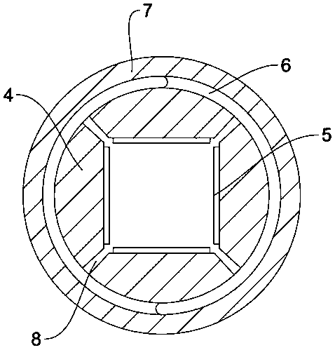
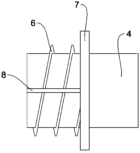
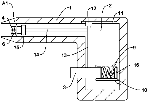
[0024] Embodiment 1: According to the instruction manual Figure 1-3 It can be seen that when in use, the port of the gun body 1 is centered on the bracket, and the top plate A1 is pressed against the teeth, and the fixed square ring 4 is aligned with the bracket, and the front end of the fixed square ring 4 is divided into four under the action of the groove 8. In equal parts, force is applied to the front end of the fixed square ring 4, so that the front end of the fixed square ring 4 is opened. At this time, the fixed square ring 4 is respectively installed on the two wings of the bracket. Connected in the groove of the bracket, the fixed square ring 4 preliminarily clamps and fixes the four corners of the bracket, and the buffer pad 5 can prevent the force from acting on a point on the bracket. At this time, the tightening ring 7 is tightened. The inner ring of the ring 7 is threaded, and matches the thread 6 at the outer ring of the fixed square ring 4, so that the fasten...

Embodiment 2

[0025] Embodiment 2: According to the instruction manual Figure 1-2 and instruction manual attached image 3It can be seen that when in use, the port of gun body 1 is centered on the bracket, and the top plate A1 is pressed against the teeth, and a force is applied to the push block 3. At this time, the push block 3 moves to the inner cavity 2, and one end of the push block 3 Contact with the baffle 18 and apply a thrust to the baffle 18. At this time, the baffle 18 has a tendency to rotate. Under the action of the shaft 17, the baffle 18 rotates with the shaft 17 as the center of the circle. At this time, the baffle 18 also One end pushes the movable plate 20, and the movable plate 20 applies a thrust to the moving rod 19, so that the moving rod 19 moves along the passing path on the mounting plate 24. At this time, the return spring 23 is compressed by force, and the other end of the moving rod 19 pushes the connecting plate 21, Thereby the connecting plate 21 pushes the f...


PUM


Abstract

The invention discloses an adjustable bracket taking gun for orthodontic treatment and relates to the technical field of orthodontic treatment brackets. The adjustable bracket taking gun comprises a gun body and is characterized in that push plates are mounted at the gunpoint of the gun body, the gun body is provided with an inner cavity inside, a pressing block is movably mounted on the gun body,one end of the pressing block is located in the inner cavity, the other end of the pressing block extends out of the gun body, a fixing square ring is mounted at the gunpoint of the gun body, and a linkage component is mounted in the inner cavity. The adjustable bracket taking gun has the advantages that pressure is directly applied to the pressing block through hand movement to indirectly applytensile force to a tightening steel wire so as to allow the tightening steel wire to apply tensile force to the fixing square ring, the front end of the fixing square ring moves towards the inner cavity of the gun body to allow the front end of the fixing square ring to clamp and fix two wings of a bracket, and tightening and fixing is achieved through a fastening ring to effectively fix the fourcorners of the fixing square ring; the grooves of the fixing square ring separates the fixing square ring into four equal blocks, so that the bracket fixing range of the fixing square ring can be increased, and brackets of different sizes can be clamped and fixed.

Description

technical field [0001] The invention relates to the technical field of orthodontic brackets, in particular to an adjustable bracket extraction gun for orthodontics. Background technique [0002] Brackets are an important part of fixed orthodontic technology. They are directly bonded to the crown surface with adhesives, and arch wires pass through the brackets to exert various types of orthodontic forces on the teeth. Brackets are made of stainless steel, bioceramic or composite resin, and their main function is to fix the arch wire, so that the arch wire can play a better role and transmit the orthodontic force, so as to control the three-dimensional movement of the teeth and achieve the purpose of orthodontic treatment. [0003] In the process of orthodontics, it is sometimes necessary to remove the bonded brackets and adjust the position before re-bonding. The current general-purpose bracket removal pliers are generally used to destructively remove the brackets after the e...

Claims


Application Information

Patent Timeline
Patent Type & Authority Applications(China)
IPC IPC(8): A61C7/02
CPCA61C7/023
Inventor 闫颖
Owner CHANGZHOU NO 2 PEOPLES HOSPITAL
Learn More