A method for forming composite I-beams
A composite material and I-beam technology, which is applied to household appliances, other household appliances, household components, etc., can solve the problems of difficult to meet the requirements of appearance quality, uneven thickness of I-shaped structural beam webs, edge strips, etc. Excellent quality, reduced processing cost, uniform thickness
- Summary
- Abstract
- Description
- Claims
- Application Information
AI Technical Summary
Problems solved by technology
Method used
Image
Examples
Embodiment 2
[0032] A method for forming a composite I-beam is characterized in that it comprises the steps of:
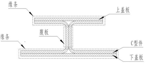
[0033] Step 1: First, complete the laying and compaction of the left and right C-shaped parts of the I-beam, the upper and lower cover plates on the upper mold body 1 of the forming mold, the lower mold body 2 of the forming mold, and the pressure plate 5;
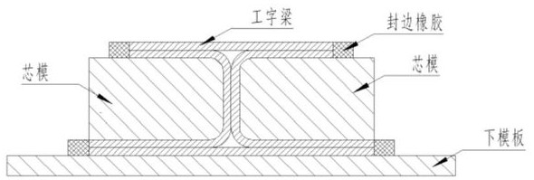
[0034] Step 2: After the lay-up and compaction of the prepreg blanks of each part of the I-beam are completed, the blanks are not removed from the mold body, and the upper mold body 1 of the forming mold, the lower mold body 2 of the forming mold, and the pressing plate are directly placed 5 are assembled together by the positioning support structure and the movable pin 6,
[0035] Step 3: Complete vacuum bagging of the assembly obtained in step 2 in the tooling vacuum bagging area;
[0036] Step 4: Transfer the packaged system to an autoclave for curing.
Embodiment 1
[0038] A method for forming a composite I-beam is characterized in that it comprises the steps of:
[0039] Step 1: First, complete the laying and compaction of the left and right C-shaped parts of the I-beam, the upper and lower cover plates on the upper mold body 1 of the forming mold, the lower mold body 2 of the forming mold, and the pressure plate 5;
[0040] Step 2: After the lay-up and compaction of the prepreg blanks of each part of the I-beam are completed, the blanks are not removed from the mold body, and the upper mold body 1 of the forming mold, the lower mold body 2 of the forming mold, and the pressing plate are directly placed 5 assembled together by positioning support structure and movable pin 6,
[0041] Step 3: Complete vacuum bagging of the assembly obtained in step 2 in the tooling vacuum bagging area;
[0042] Step 4: Transfer the packaged system to an autoclave for curing.
[0043] A mold for forming a composite I-beam includes a forming mold upper mo...
Embodiment 3
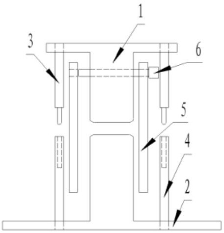
[0045] A mold for forming a composite I-beam includes a forming die upper die body 1 and a forming die lower die body 2, characterized in that: the forming die upper die body 1 and the forming die lower die body 2 are in an H-shaped vertical In conjunction, a positioning support structure is set between the upper mold body 1 of the forming mold and the lower mold body 2 of the forming mold. The upper mold body 1 of the forming mold is provided with penetrating pin holes, and pressure plates 5 are provided on both sides.
[0046] The pressing plate 5 is located on both sides of the forming die, and the pressing plate 5 is provided with pin holes, and is connected with the upper mold body 1 of the forming die by the movable pin 6, and the pressing plate 5 can be displaced in the horizontal direction after being connected by the movable pin 6.
[0047] The positioning support rod 3 and the positioning support pile 4 are arranged diagonally between the upper mold body 1 of the form...
PUM
 Abstract
Description
Claims
Application Information
 - R&D
- Intellectual Property
- Life Sciences
- Materials
- Tech Scout
- Unparalleled Data Quality
- Higher Quality Content
- 60% Fewer Hallucinations
Browse by: Latest US Patents, China's latest patents, Technical Efficacy Thesaurus, Application Domain, Technology Topic, Popular Technical Reports.
© 2025 PatSnap. All rights reserved.Legal|Privacy policy|Modern Slavery Act Transparency Statement|Sitemap|About US| Contact US: help@patsnap.com


