Die and method for forming composite material I-shaped beam

A technology of composite materials and forming molds, which is applied in household appliances, other household appliances, household components, etc., can solve the problems of difficult to meet the requirements of appearance quality, uneven thickness of I-shaped structural beam webs, and edge strips, and achieve appearance quality Excellent, reduced processing cost, uniform thickness effect

Active Publication Date: 2019-10-29
CHENGDU AIRCRAFT INDUSTRY GROUP
View PDF6 Cites 13 Cited by
  • Summary
  • Abstract
  • Description
  • Claims
  • Application Information

AI Technical Summary

Problems solved by technology

[0004] The curing process in the above-mentioned prior art is a thermal reaction process. In the early stage of heating, the resin in the layup is softened by heat, and the left and right mandrels lose the support of the bottom layup. Due to gravity and external pressure, they are prone to roll, which in turn causes The local pressure in the web and edge area is insufficient. Therefore, after solidification and molding, the thickness of the web and edge of the I-shaped structural beam is often uneven, and the appearance quality is difficult to meet the requirements, and it is easy to have quality problems in non-destructive testing, especially When the thickness of the parts is large, it is easy to cause the shortage of scrapped parts. The invention provides a mold and method for forming I-beams made of composite materials.

Method used


Image

  • Die and method for forming composite material I-shaped beam
  • Die and method for forming composite material I-shaped beam
  • Die and method for forming composite material I-shaped beam

Examples


Embodiment 2

[0032] A method for forming a composite I-beam is characterized in that it comprises the steps of:

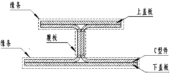
[0033] Step 1: First, complete the laying and compaction of the left and right C-shaped parts of the I-beam, the upper and lower cover plates on the upper mold body 1 of the forming mold, the lower mold body 2 of the forming mold, and the pressure plate 5;

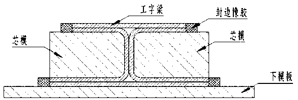
[0034] Step 2: After the lay-up and compaction of the prepreg blanks of each part of the I-beam are completed, the blanks are not removed from the mold body, and the upper mold body 1 of the forming mold, the lower mold body 2 of the forming mold, and the pressing plate are directly placed 5 are assembled together by the positioning support structure and the movable pin 6,

[0035] Step 3: Complete vacuum bagging of the assembly obtained in step 2 in the tooling vacuum bagging area;

[0036] Step 4: Transfer the packaged system to an autoclave for curing.

Embodiment 1

[0038] A method for forming a composite I-beam is characterized in that it comprises the steps of:

[0039] Step 1: First, complete the laying and compaction of the left and right C-shaped parts of the I-beam, the upper and lower cover plates on the upper mold body 1 of the forming mold, the lower mold body 2 of the forming mold, and the pressure plate 5;

[0040] Step 2: After the lay-up and compaction of the prepreg blanks of each part of the I-beam are completed, the blanks are not removed from the mold body, and the upper mold body 1 of the forming mold, the lower mold body 2 of the forming mold, and the pressing plate are directly placed 5 are assembled together by the positioning support structure and the movable pin 6,

[0041] Step 3: Complete vacuum bagging of the assembly obtained in step 2 in the tooling vacuum bagging area;

[0042] Step 4: Transfer the packaged system to an autoclave for curing.

[0043] A mold for forming a composite I-beam includes a forming d...

Embodiment 3

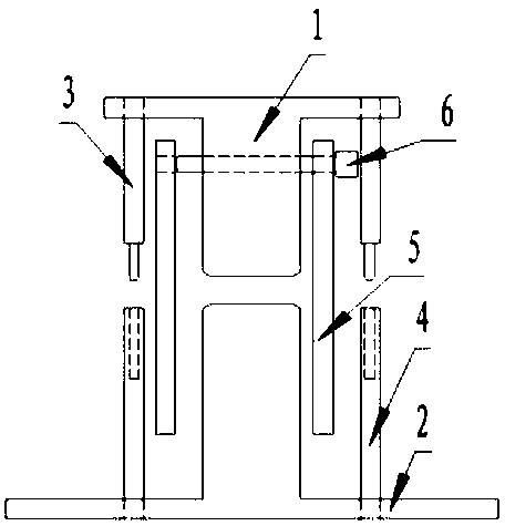
[0045] A mold for forming a composite I-beam includes a forming die upper die body 1 and a forming die lower die body 2, characterized in that: the forming die upper die body 1 and the forming die lower die body 2 are in an H-shaped vertical In combination, a positioning support structure is set between the upper mold body 1 of the forming mold and the lower mold body 2 of the forming mold. The upper mold body 1 of the forming mold is provided with penetrating pin holes, and pressure plates 5 are provided on both sides.

[0046] The pressing plate 5 is located on both sides of the forming die, and the pressing plate 5 is provided with pin holes, and is connected with the upper mold body 1 of the forming die by the movable pin 6, and the pressing plate 5 can be displaced in the horizontal direction after being connected by the movable pin 6.

[0047] The positioning support rod 3 and the positioning support pile 4 are arranged diagonally between the upper mold body 1 of the form...


PUM


Abstract

The invention relates to a method for forming a composite material I-shaped beam. The method is characterized by comprising the following steps: step one, first separately laying and compacting a leftC-shaped member, a right C-shaped member, and upper and lower cover plates of an I-shaped beam on an upper die body of a forming die, a lower die body of the forming die and a pressing plate; step two, after the laying and compacting work of all prepreg blanks of the I-shaped beam is finished, taking down the blanks from the die bodies, and directly assembling the upper die body of the forming die, the lower die body of the forming die and the pressing plate by a positioning and supporting structure and moving pins; step three, finishing package of an assembly obtained in the second step by using a vacuum bag in a tooling vacuum bag packaging area; and step four, transferring a packaged system in an autoclave for curing. The die for forming the composite material I-shaped beam comprises the upper die body of the forming die and the lower die body of the forming die; the upper die body of the forming die and the lower die body of the forming die are in H-shaped vertical involution; andthe positioning and supporting structure is arranged between the upper die body of the forming die and the lower die body of the forming die.

Description

technical field [0001] The invention relates to an H-shaped molding die of a composite material I-shaped structural beam part and a manufacturing technical scheme, in particular to a composite material I-shaped structural beam molding die with a relatively large thickness and a technical manufacturing method. Background technique [0002] The I-shaped structural beam is a beam-rib form commonly used in aircraft composite structures. It is widely used as the main structural form in laminated plate beams. It is mostly used for girders and ribs in wing surface structures, longitudinal beam. The structural beam is composed of left and right C-shaped pieces, upper and lower cover plates and core materials. [0003] The original "I"-shaped structural beam forming tooling is a modular structure, which is mostly composed of the lower formwork, left and right mandrels. When forming, first complete the laying of C-shaped parts on the left and right mandrels, and then The upper and l...

Claims


Application Information

Patent Timeline
Patent Type & Authority Applications(China)
IPC IPC(8): B29C70/34B29C70/44B29C70/54B29C33/00B29L31/30
CPCB29C33/00B29C70/342B29C70/446B29C70/54B29L2031/3076
Inventor 徐伟伟程勇马瑞张超李博
Owner CHENGDU AIRCRAFT INDUSTRY GROUP
Why Eureka
Try Eureka