Rainwater collecting device

A rainwater collection device, rainwater technology, applied in water supply devices, drinking water devices, general water supply conservation, etc., can solve problems such as inconvenience in rainwater treatment

Inactive Publication Date: 2019-11-01
徐寿林
View PDF1 Cites 2 Cited by
  • Summary
  • Abstract
  • Description
  • Claims
  • Application Information

AI Technical Summary

Problems solved by technology

[0003] The purpose of the present invention is to provide a rainwater collection device, which solves the technical problem of inconvenient rainwater treatment in the prior art

Method used


Image

  • Rainwater collecting device
  • Rainwater collecting device
  • Rainwater collecting device

Examples


Embodiment

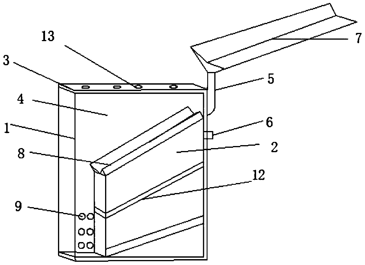
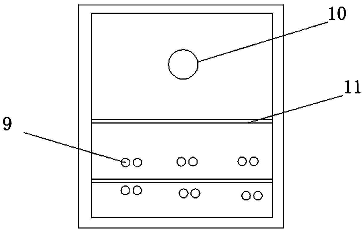
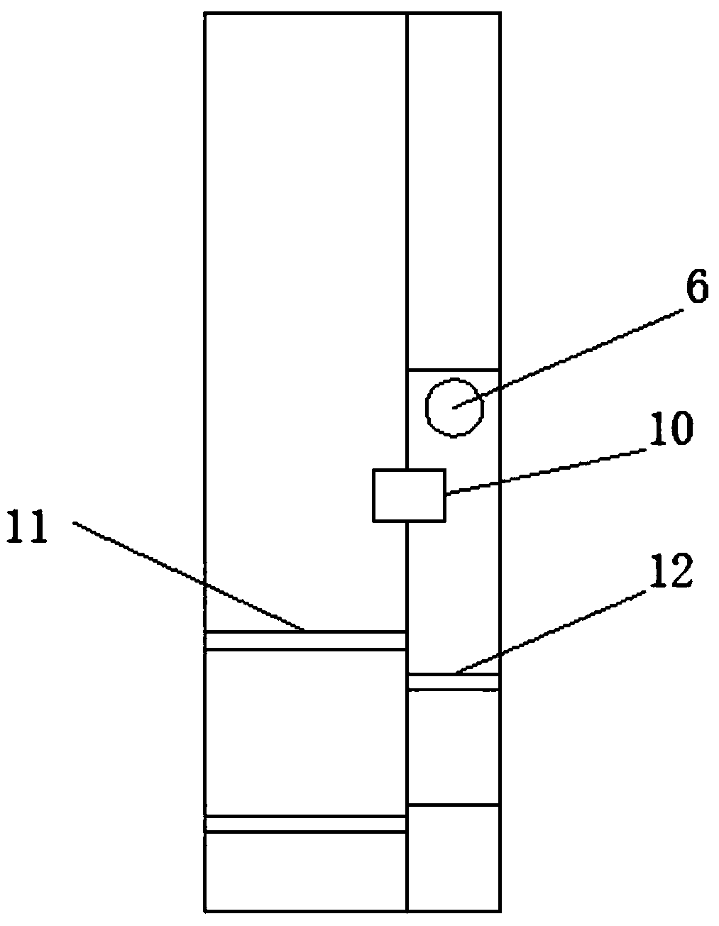
[0026] Such as Figure 1-3 As shown, a rainwater collection device provided by the present invention includes a rainwater treatment chamber 1, a rainwater outlet chamber 2 and a collection chamber 3. The inside of the collection chamber 3 is separated into the rainwater treatment chamber 1 and the rainwater collection chamber 1 by a partition plate 4 The water outlet chamber 2, and the outside of the collection chamber 3 are connected with a rainwater inlet pipe 5 and a rainwater outlet pipe 6, the rainwater inlet pipe 5 is located above the rainwater outlet pipe 6, and the rainwater inlet pipe 5 is connected with a first collection tank 7 above the lower end It is connected with a second collection tank 8, the second collection tank 8 is located inside the collection chamber 3, and the second collection tank 8 is installed above the rainwater outlet chamber 2; the present invention is provided with two cavities for circulating treatment respectively At the same time, the rain...


PUM


Abstract

The invention discloses a rainwater collecting device. The rainwater collecting device comprises a rainwater treatment cavity, a rainwater outlet cavity and a collecting cavity; the internal of the collecting cavity is divided into the rainwater treatment cavity and the rainwater outlet cavity through a separation plate; the outer side of the collecting cavity communicates with a rainwater inlet pipe and a rainwater outlet pipe; the rainwater inlet pipe is positioned above the rainwater outlet pipe; a first collecting tank communicates above the rainwater inlet pipe, and a second collecting tank communicates to the lower end; and the second collecting tank is positioned in the collecting cavity, and is mounted above the rainwater outlet cavity. The rainwater collecting device solves the technical problem of inconvenience for rainwater treatment in the prior art.

Description

technical field [0001] The invention relates to the technical field of rainwater treatment, in particular to a rainwater collection device. Background technique [0002] The resource utilization of urban rainwater and the collection and utilization of rainwater are effective ways to solve the shortage of water resources. A rainwater collector with the publication number CN205822327U includes a box body, a rotating shaft, a flap, a rainwater inlet, an initial rainwater collection tank, and an initial rainwater drainage Valve, clean rainwater collection tank and clean rainwater discharge pipe, the position of the flap close to the lower part of the box body is provided with a buoy, the end of the flap connected to the buoy is provided with a folding plate, and one end of the flap is hinged to the flap, The other end is hinged with the box body. Through the above scheme, the box body provides space for the diversion of rainwater. The rotating shaft is hinged on both sides of t...

Claims


Application Information

Patent Timeline
Patent Type & Authority Applications(China)
IPC IPC(8): E03B3/02
CPCE03B3/02Y02A20/108
Inventor 徐寿林
Owner 徐寿林
Why Eureka
Try Eureka