Air purification equipment for industrial waste gas emission

A technology for air purification equipment and industrial waste gas, which is applied in the direction of chemical instruments and methods, combined devices, and separation of dispersed particles, which can solve the problems of difficult disassembly of filter screens, and achieve the effect of improving operation efficiency, improving treatment effect, and simple disassembly

Active Publication Date: 2022-01-14
WUXI MIANJIANG HVAC ENVIRONMENTAL PROTECTION EQUIP CO LTD
View PDF25 Cites 1 Cited by
  • Summary
  • Abstract
  • Description
  • Claims
  • Application Information

AI Technical Summary

Problems solved by technology

[0005] The purpose of the present invention is to reduce the problem that the filter screen is difficult to disassemble in the air purification equipment through the pull-out design of the intercepting tooth plate, and at the same time to install the blocking plate so that the factory air purification device does not stop working. The staff can still disassemble and replace the filter screen, which greatly improves the working efficiency of the factory. At the same time, the low-temperature hydraulic pipe and lime plate installed in the entire air purification device process the water vapor in the exhaust gas to prevent the waste gas with water vapor from directly acting on the air. On the activated carbon plate, the adsorption effect of the activated carbon plate is greatly reduced. Finally, the second electric push rod drives the movable plate and the sealing block to realize free opening and closing of the air guide pipe on the circulating filter tank, so that the exhaust gas can be purified more thoroughly on the activated carbon plate

Method used


Image

  • Air purification equipment for industrial waste gas emission
  • Air purification equipment for industrial waste gas emission
  • Air purification equipment for industrial waste gas emission

Examples


Embodiment 1

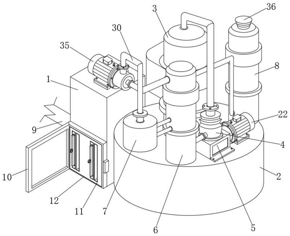
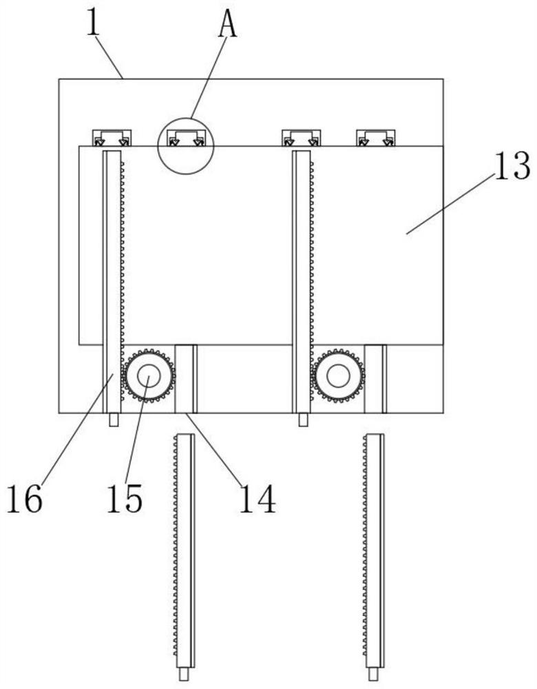
[0034] Such as Figure 1-4As shown, a kind of air purification equipment used for industrial exhaust gas discharge disassembles and replaces the filter plate in the equipment. Open the lock, open the airtight door 10, and at the same time, the staff put on the mask in advance to prevent some exhaust gas from being exposed and affect the staff. The staff prepares the clean intercepting tooth plate 16 in advance, and puts the blocking plate 14 on the interface 11 Immediately insert the new intercepting tooth plate 16 into the interface 11 while taking it off, and when the new intercepting tooth plate 16 enters the interface 11, the gear teeth on the intercepting tooth plate 16 act on the dust removal box 1. Gear 15, causing the old intercepting tooth plate 16 to be unscrewed while the gear 15 is rotating;

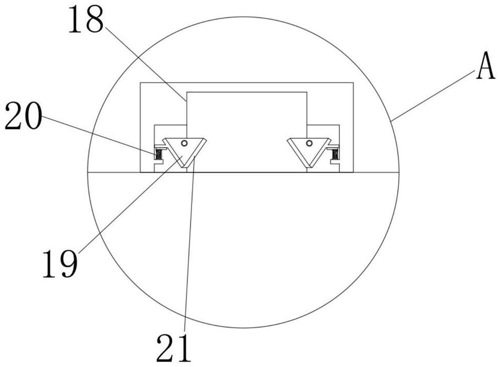
[0035] When the front end of the new intercepting tooth plate 16 enters the slot 18 on the filter cavity 13, the exhaust gas inlet pipe 9 is connected to the filter cavity 1...

Embodiment 2

[0037] Such as Figure 5-6 As shown, an air purification device for industrial waste gas discharge performs scrubbing treatment on the waste gas in the device. During specific operation, the large particle impurities in the waste gas are removed by intercepting the filter screen 17 on the intercepting tooth plate 16. At this time, the industrial waste gas is also doped with a large amount of harmful gases soluble in water. By scrubbing the waste gas, the harmful waste gas is dissolved in water, and then the reagent is directly added to the solution, making the treatment of industrial waste gas simpler and safer;

[0038] The filter cavity 13 is connected with the exhaust pipe 27, and the exhaust gas enters the shower box 2 through the air outlet 28 on the exhaust pipe 27. At this time, the staff turns on the water pump 22, and the water pump 22 turns on the temperature at 50-70 degrees Celsius prepared by the staff in advance. The exhaust gas treatment reagent is pressurized a...

Embodiment 3

[0042] Such as Figure 8-10 As shown, a kind of air purification equipment used for industrial waste gas discharge performs circular adsorption treatment on the waste gas. During specific operation, the exhaust pump 35 draws the waste gas in the circulating filter tank 6 from the bottom. At this time, the second electric push rod 38 Start to work, the sealing block 39 on the fixed plate 33 is released, and the front end of the second electric push rod 38 is connected with the connecting rod 322, and the second electric push rod 38 is elongated, driving the connecting rod 322 to elongate, and the elongated connecting rod 322 During the rising process, the limit rod 325 is pushed upward in the limit groove 324, and the connecting rod 322 drives the sealing plate 323 to be pushed out from the vent 326 of the movable plate 321 on the partition mechanism 32, because the rising connecting rod 322 drives the entire movable plate 321 The recirculation filter tank 6 rises in the tank b...


PUM


Abstract

The invention discloses air purification equipment for industrial waste gas emission, and relates to the technical field of waste gas purification. The air purification equipment comprises a dust removal box, a shower box, a condensation box, a circulating filtering tank, a rotary impurity removal tank, an exhaust tank, a gas guide pipe and a gas inlet pipe, wherein the circulating filtering tank is communicated with the rotary impurity removal tank through the gas guide pipe, and the exhaust tank is communicated with the circulating filtering tank through the gas guide pipe. According to the invention, an intercepting toothed plate is in meshed connection with a gear on the dust removal box, so that a worker only needs to pull out the intercepting toothed plate from the interface when replacing a filter screen in the dust removal box, meanwhile, after a new intercepting toothed plate enters, the old intercepting toothed plate is automatically discharged, and the whole filter screen is relatively simple to disassemble. Meanwhile, when the worker disassembles the intercepting toothed plate, the whole air purification equipment for the factory is still in a working state, waste gas treatment in the factory cannot be affected, and the working efficiency of the whole factory is improved.

Description

technical field [0001] The invention relates to the technical field of waste gas purification, in particular to an air purification device for industrial waste gas discharge. Background technique [0002] Industrial waste gas refers to the general term of various pollutant gases discharged into the air generated during fuel combustion and production processes in the factory area. These waste gases include: carbon dioxide, carbon disulfide, hydrogen sulfide, fluoride, nitrogen oxides, chlorine, hydrogen chloride , carbon monoxide, sulfuric acid mist lead mercury, beryllium compounds, smoke and productive dust, if discharged into the atmosphere, will pollute the air. These substances enter the human body through the respiratory tract through different channels, some directly cause harm, and some have accumulation effects. will seriously endanger human health; [0003] In the actual use of traditional factory air purification equipment, since the filter mechanism of the first ...

Claims


Application Information

Patent Timeline
Patent Type & Authority Applications(China)
IPC IPC(8): B01D50/60B01D53/00B01D53/04B01D53/18B01D53/26
CPCB01D53/002B01D53/04B01D53/18B01D53/26Y02A50/2351
Inventor 钟上明易明宝吴继辉
Owner WUXI MIANJIANG HVAC ENVIRONMENTAL PROTECTION EQUIP CO LTD
Why Eureka
Try Eureka