CAN expander and CAN network bus system

A CAN bus, expander technology, applied in the field of communication, can solve problems such as trouble, and achieve the effect of automatic access

Pending Publication Date: 2019-11-01
SHENZHEN MEGMEET ELECTRICAL CO LTD
View PDF0 Cites 2 Cited by
  • Summary
  • Abstract
  • Description
  • Claims
  • Application Information

AI Technical Summary

Problems solved by technology

[0003] In the process of realizing the embodiment of the present invention, the inventors found that there are at least the following problems in the above related technologies: the nodes are connected to the CAN bus through the CAN expander to realize the communication between the nodes, and the CAN expanders placed at the beginning and the end of the CAN bus Terminal resistors need to be connected. When a new node needs to be connected, it is necessary to manually judge whether there is and only the CAN bus at the first and last ends is included in the terminal resistance after the new node is connected, and manually connect and set the terminal resistors at the first and last ends. very troublesome

Method used


Image

  • CAN expander and CAN network bus system
  • CAN expander and CAN network bus system
  • CAN expander and CAN network bus system

Examples


Embodiment 1

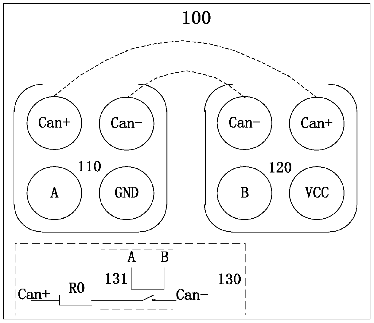
[0034] The embodiment of the present invention provides a CAN extender, please refer to figure 1 , Is a schematic structural diagram of a CAN extender provided by an embodiment of the present invention. The CAN extender 100 includes: a first docking unit 110, a second docking unit 120, and a switch circuit 130.

[0035] The first docking unit 110 includes: a first high-order data port Can+, a first low-order data port Can-, a first connection port A, and a ground port GND.

[0036] The second docking unit 120 includes: a second high data port Can+, a second low data port Can-, a second connection port B and a power port VCC, the second high data port Can+ and the first high data port Can+ is connected, and the second lower data port Can- is connected to the first lower data port Can-.

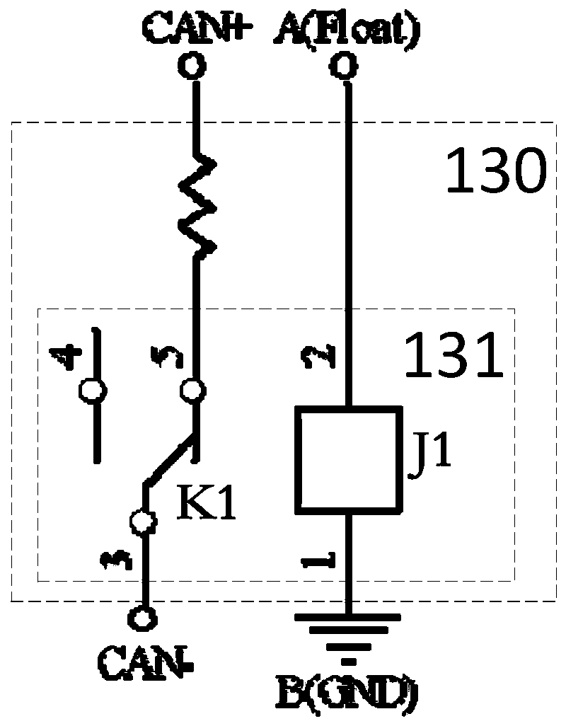
[0037] The switch circuit 130 is connected between the first connection port A and the second connection port B, the switch circuit 130 includes a terminal resistor R0, and the terminal resistor R0 is...

Embodiment 2

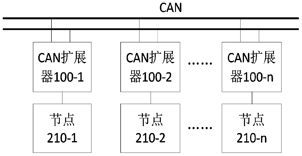
[0046] The embodiment of the present invention provides a CAN network bus system, please refer to image 3 , Is a structural block diagram of a CAN network bus system provided by an embodiment of the present invention. The CAN network bus system 200 includes: a CAN bus and at least two CAN extenders according to any one of claims 1 to 6 100. The at least two CAN extenders 100 are respectively connected to the CAN bus in communication.

[0047] In the embodiment of the present invention, there are n CAN extenders 100, therefore, image 3 The CAN network bus system shown is provided with a CAN extender 100-1, a CAN extender 100-2, ..., a CAN extender 100-n, where n represents a positive integer.

[0048] It should be noted that since the CAN extender in this embodiment can be the CAN extender described in the first embodiment, the corresponding content of the CAN extender in the first embodiment is also applicable to this embodiment, and will not be omitted here. Detailed.

[0049] Th...


PUM


Abstract

The embodiment of the invention relates to the technical field of communication, and discloses a CAN expander and a CAN network bus system. The CAN expander comprises a first butt joint unit, a secondbutt joint unit and a switching circuit, the switch circuit is connected between a first connection port of the first butt joint unit and a second connection port of the second butt joint unit. The switching circuit comprises a terminal resistor, wherein the first switching unit is arranged between a first high-order data port and a first low-order data port in the first butt joint unit; and theswitching circuit is used for controlling the on-off of the terminal resistor between the first high-order data port and the first low-order data port according to the levels of the first connecting port and the second connecting port, so as to realize the automatic access of the terminal resistor.

Description

Technical field [0001] The embodiment of the present invention relates to the field of communication technology, in particular to a CAN extender and a CAN network bus system. Background technique [0002] The Controller Area Network (CAN) bus is a field bus that can be used to construct a serial communication network. According to the transmission line theory, the signal is transmitted in the transmission line. When the transmission distance exceeds a certain length, the anti-interference ability of the communication bus will decrease. If it encounters a discontinuous transmission medium, reflection will occur. The principle of the reflection phenomenon is related to light. The principle of the reflection phenomenon of a signal from one medium to another is similar. Because the impedance of the CAN bus transceiver is relatively high, the pair of differential lines that constitute the CAN bus are isolated from each other and not connected together. When the signal is transmitted ...

Claims


Application Information

Patent Timeline
Patent Type & Authority Applications(China)
IPC IPC(8): H04L12/40
CPCH04L12/40006H04L2012/40215
Inventor 杨武郑健州
Owner SHENZHEN MEGMEET ELECTRICAL CO LTD
Why Eureka
Try Eureka