Staged roller biomass dryer

A biomass and graded technology, which is applied in the field of dryers and graded drum biomass dryers, can solve the problems of increasing the moisture content of the dryer, easily causing no-load hot air, and not being able to dry immediately, so as to improve the drying efficiency. Improve production efficiency, facilitate process layout, and reduce building area

Inactive Publication Date: 2019-11-05
ANHUI HUANTAI BIO ENERGY TECH DEV
View PDF7 Cites 1 Cited by
  • Summary
  • Abstract
  • Description
  • Claims
  • Application Information

AI Technical Summary

Problems solved by technology

[0002] The drying of biomass raw materials is a key part of the industrial application of biomass. The drying state of raw materials directly affects the efficiency and income of subsequent processes; treatment; at present, large-scale drying boxes and tunnel drying already exist, such as using hot air to heat the inside of the drum while blowing away the humid air to achieve the purpose of drying; but there are many problems in the drying process, and the current circulation During the drying process of the biomass dryer, the biomass is dried at one time, which causes the moisture released from drying to not be dried immediately, which increases the moisture content in the dryer and reduces the drying rate; at the same time, due to the existing drying The length of the cylinder is very long, and the temperature requirement of the heat source is also very high, otherwise the purpose of drying will not be achieved, but if the temperature is too high, it will easily lead to partial overheating of the dryer, carbonization of raw materials, and fire in serious cases; in addition, the space inside the cylinder is large , the amount of hot air required is large, and it is easy to cause the hot air to be empty, and the hot air generated by drying is often discharged, which wastes energy and leads to high energy consumption.

Method used


Image

  • Staged roller biomass dryer
  • Staged roller biomass dryer

Examples


Embodiment 1

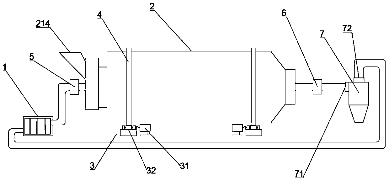
[0018] Such as Figure 1 to Figure 2 As shown, a graded drum biomass dryer includes a heat source 1, a drying drum 2 and a power unit 3,

[0019] The outer wall of the drying cylinder 2 is provided with a wheel belt 4, and the power device 3 includes a motor 31 and a supporting wheel 32, and the supporting wheel 32 is in close contact with the wheel belt 4;

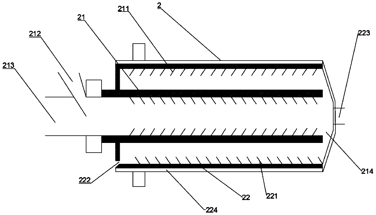
[0020] The drying cylinder 2 is divided into an inner cylinder 21 and an outer cylinder 22, and the inner cylinder 21 is embedded in the outer cylinder 22; the inner side walls of the inner cylinder 21 and the outer cylinder 22 are respectively provided with a first spiral lifter 211 and a The second spiral flight 221, the spiral direction of the first spiral flight 211 and the second spiral flight 221 is opposite, one end of the inner cylinder 21 is provided with a feed hopper 212 and an air inlet 213, and the other end is provided with a falling A feed port 214; the bottom of one end of the outer cylinder 22 near the f...


PUM


Abstract

The invention relates to a staged roller biomass dryer. The staged roller biomass dryer comprises a heat source, a drying cylinder and a power device; a wheel belt is arranged on the outer side wall of the drying cylinder; the power device comprises a motor and a support wheel; the support wheel is tightly contacted with the wheel belt; the drying cylinder is divided into an inner cylinder and anouter cylinder; the inner cylinder is embedded in the outer cylinder; a first spiral shoveling plate and a second spiral shoveling plate are arranged on the inner side walls of the inner cylinder andthe outer cylinder, and are opposite in spiral direction; a feed hopper and an intake port are arranged at one end of the inner cylinder, and a blanking port is formed in the other end; a discharge port is formed in the bottom of the end, near the feed hopper, of the outer cylinder, and an exhaust port is formed in the other end; an air blower is arranged between the heat source and the intake port; and an induced draft fan is arranged at the external of the exhaust port. The dryer shortens the length by at least one half compared with a common dryer to facilitate the process arrangement, reduces the construction area of factory buildings, saves the engineering investment, and is more suitable for existing factory transformation process arrangement.

Description

technical field [0001] The invention belongs to the field of dryers, in particular to the field of graded drum biomass dryers. Background technique [0002] The drying of biomass raw materials is a key part of the industrial application of biomass. The drying state of raw materials directly affects the efficiency and income of subsequent processes; treatment; at present, large-scale drying boxes and tunnel drying already exist, such as using hot air to heat the inside of the drum while blowing away the humid air to achieve the purpose of drying; but there are many problems in the drying process, and the current circulation During the drying process of the biomass dryer, the biomass is dried at one time, which causes the moisture released from drying to not be dried immediately, which increases the moisture content in the dryer and reduces the drying rate; at the same time, due to the existing drying The length of the cylinder is very long, and the temperature requirement of...

Claims


Application Information

Patent Timeline
Patent Type & Authority Applications(China)
IPC IPC(8): F26B11/04F26B21/00F26B25/02F26B25/12F26B25/16
CPCF26B11/04F26B21/001F26B25/02F26B25/12F26B25/16
Inventor 马培勇范翔宇丁哲宇许本海李健雷阳阳
Owner ANHUI HUANTAI BIO ENERGY TECH DEV
Why Eureka
Try Eureka