
Determining a zero offset of a vibratory meter at a process condition

A technology of zero offset and vibration meter, which is applied in volume measurement, direct mass flow meter, instrument, etc.

Active Publication Date: 2019-11-08
MICRO MOTION INC
View PDF20 Cites 0 Cited by
  • Summary
  • Abstract
  • Description
  • Claims
  • Application Information

AI Technical Summary

Problems solved by technology

Although this initially determined zero offset can adequately correct the measurement results in limited cases, the zero offset can change over time due to changes in various operating conditions (mainly temperature), resulting in only partial corrections

Method used


Image

  • Determining a zero offset of a vibratory meter at a process condition
  • Determining a zero offset of a vibratory meter at a process condition
  • Determining a zero offset of a vibratory meter at a process condition

Examples


Embodiment Construction

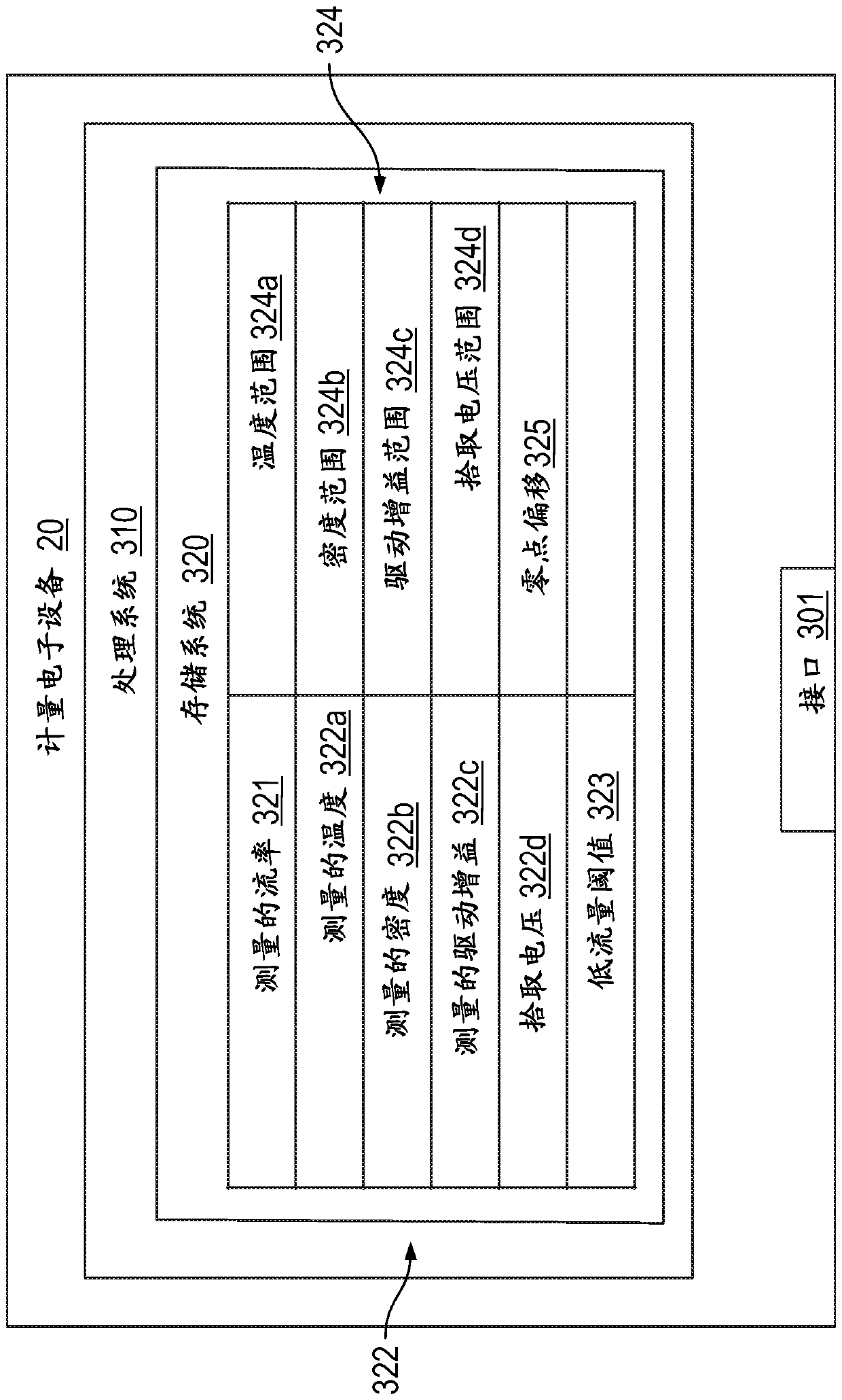
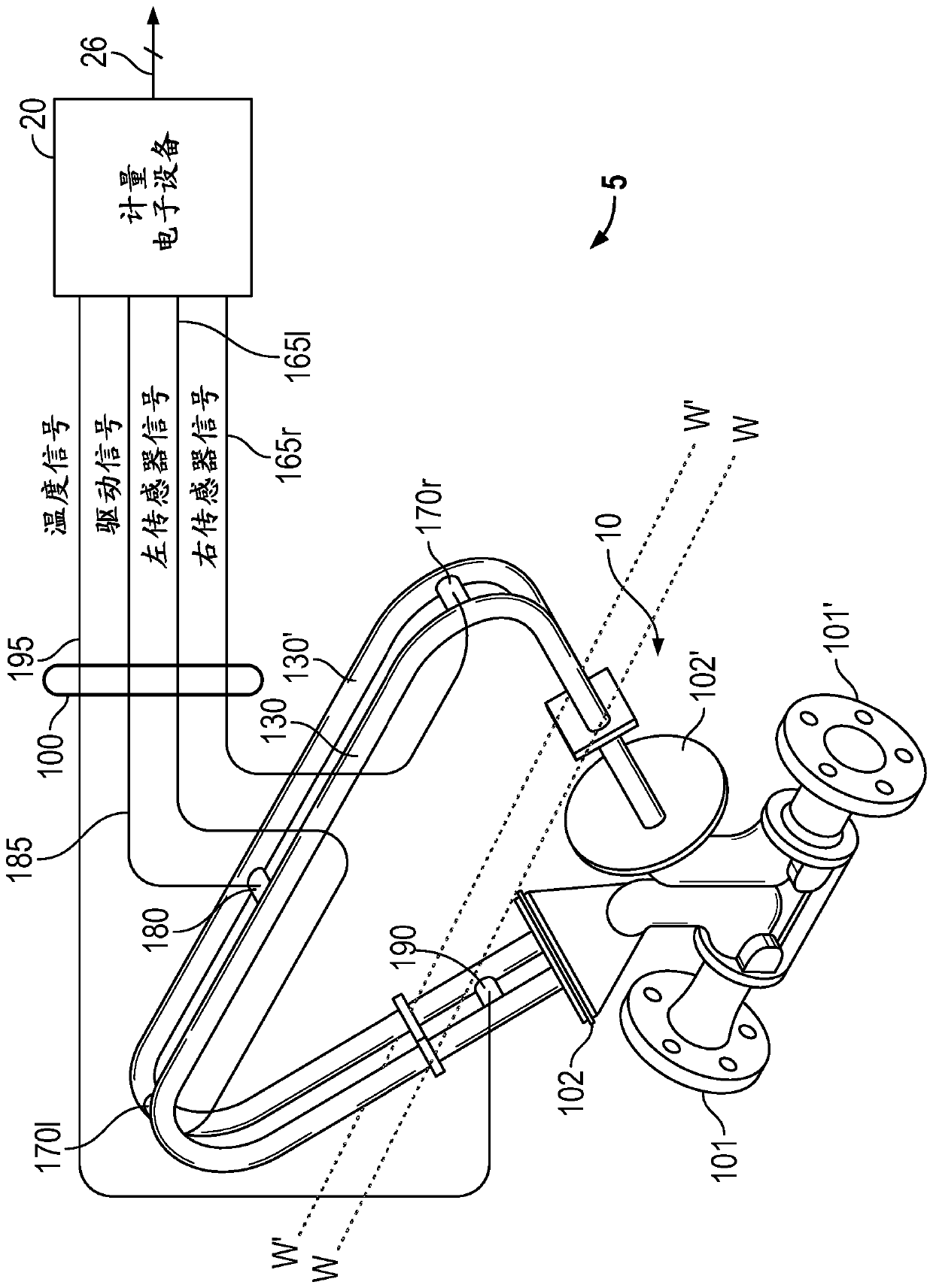
[0036] Figure 1-5and the ensuing description depict a specific example of the best mode to teach those skilled in the art how to make and use an embodiment that determines the zero offset of a vibrating meter under process conditions. For the purpose of teaching inventive principles, some conventional aspects have been simplified or omitted. Those skilled in the art will recognize variations from these examples that fall within the scope of the description. Those skilled in the art will appreciate that the features described below can be combined in various ways to form multiple variations of determining the zero offset of a vibrating meter under process conditions. As a result, the embodiments described below are not to be limited to the specific examples described below, but only by the claims and their equivalents.

[0037] The zero offset can be determined by measuring the flow rate of the substance in the vibrating meter. The method and vibrometer can determine if the...


PUM


Abstract

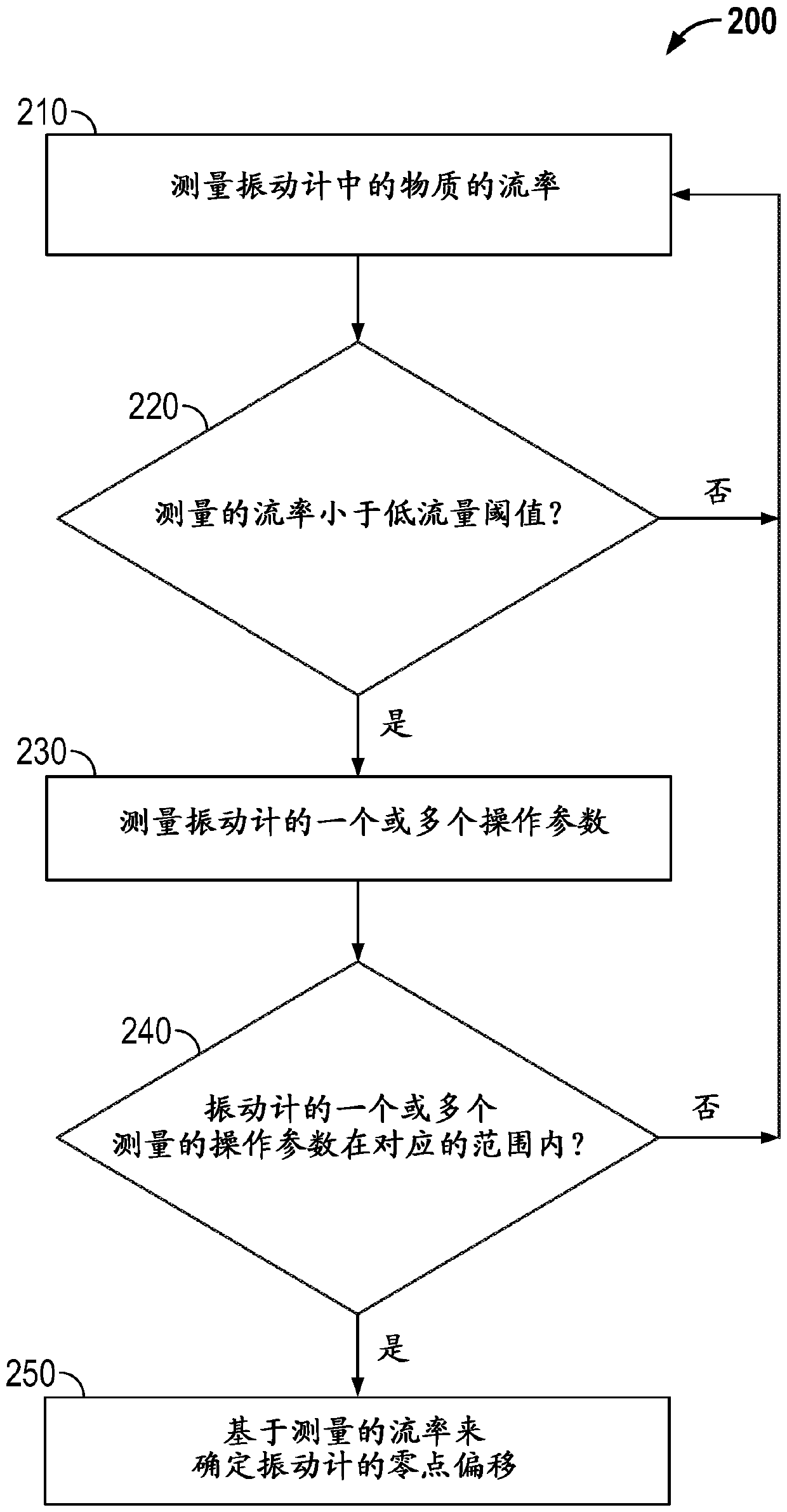
A method of determining a zero offset of a vibratory meter at a process condition is provided. The method includes measuring a flow rate of a material in the vibratory meter, determining if the measured flow rate is less than a low flow threshold, measuring one or more operational parameters of the vibratory meter, determining if the one or more measured operational parameters of the vibratory meter are within a corresponding range, and if the measured flow rate is less than the low flow threshold and if the one or more measured operational parameters of the vibratory meter are within the corresponding range, then determining a zero offset of the vibratory meter based on the measured flow rate.

Description

technical field [0001] Embodiments described below relate to determining the zero offset of a vibrating meter, and more particularly, to determining the zero offset of a vibrating meter under process conditions. Background technique [0002] Vibration sensors such as, for example, vibrating densitometers and Coriolis flow meters are generally known and are used to measure the mass flow rate and other information of material flowing through a conduit in a flow meter . Exemplary Coriolis flow meters are disclosed in U.S. Patent Nos. 4,109,524, 4,491,025, and Re. 31,450, all to J.E. Smith et al. These flow meters have one or more conduits in straight or curved configurations. Each conduit configuration in a Coriolis mass flow meter, for example, has a set of natural modes of vibration, which may be of the simple bending, torsional, or coupled type. Each catheter can be driven to oscillate in a preferred mode. [0003] Substance flows into the flow meter from a connecting co...

Claims


Application Information

Patent Timeline
IPC IPC(8): G01F1/84G01F25/00G01F15/02
CPCG01F1/8436G01F1/8477G01F15/024G01F25/10
Inventor S.D.格雷科
Owner MICRO MOTION INC
Learn More