General aircraft loudspeaker with sound amplifying function

A loudspeaker and aircraft technology, applied in the field of loudspeakers, can solve the problems of dull, ambiguous sound, affecting people to hear the loudspeaker accurately, and achieve the effect of reducing resonance, clear sound and good amplification effect.

Active Publication Date: 2019-11-12
江西冠一通用飞机有限公司 +1
View PDF5 Cites 1 Cited by
  • Summary
  • Abstract
  • Description
  • Claims
  • Application Information

AI Technical Summary

Problems solved by technology

[0002] The loudspeaker is a transducer device that converts electrical signals into acoustic signals. It is mainly composed of magnets, frames, centering supports, and molded ring cones. It is an important component in audio and broadcasting systems. The loudspeaker is based on the principle And structures can be divided into many types, which are widely used in all walks of life. In the broadcasting system and sound system in the aircraft, speakers are also needed for broadcasting and playing video music. However, for the sake of beauty, the aircraft The internal broadcast system and sound system are embedded in the shell of the interior layer and kept flush with the interior surface. In this case, when the speaker is working, most of the sound waves are transmitted into the interior layer, and in the Resonance occurs in the interior layer, which causes the sound played by the speaker to be dull and ambiguous, which affects people's accurate hearing of the content broadcast by the speaker, thereby affecting the normal operation of the broadcasting system and the sound system

Method used


Image

  • General aircraft loudspeaker with sound amplifying function
  • General aircraft loudspeaker with sound amplifying function
  • General aircraft loudspeaker with sound amplifying function

Examples


Embodiment Construction

[0022] In order to make the technical means, creative features, goals and effects achieved by the present invention easy to understand, the present invention will be further described below in conjunction with specific embodiments.

[0023] In the description of the present invention, it should be noted that the terms "upper", "lower", "inner", "outer", "front end", "rear end", "both ends", "one end", "another end" The orientation or positional relationship indicated by etc. is based on the orientation or positional relationship shown in the drawings, and is only for the convenience of describing the present invention and simplifying the description, rather than indicating or implying that the referred device or element must have a specific orientation, use a specific Azimuth configuration and operation, therefore, should not be construed as limiting the invention. In addition, the terms "first" and "second" are used for descriptive purposes only, and should not be understood ...


PUM


Abstract

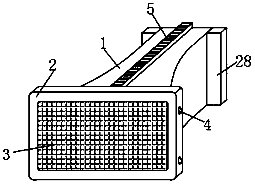
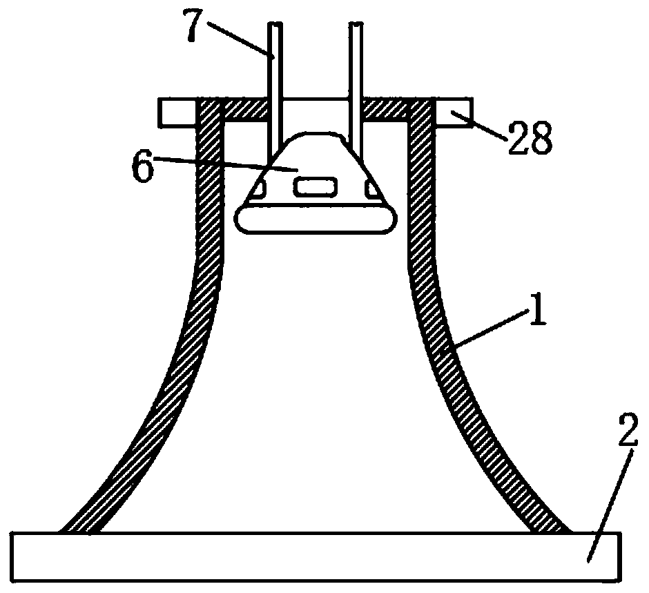
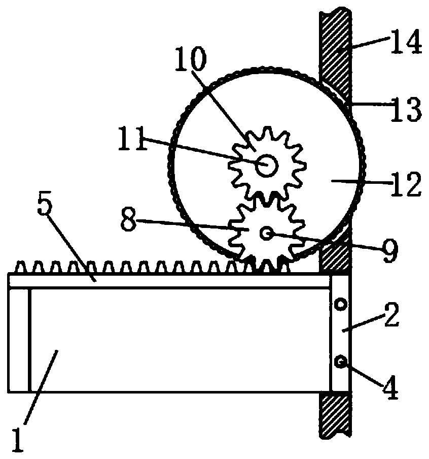
The invention discloses a general aircraft loudspeaker with a sound amplifying function. The general aircraft loudspeaker comprises a sound amplifying shell, the sound amplifying shell is movably installed in an installation cavity of an interior shell of an aircraft, a panel is fixedly installed at the front end of the sound amplifying shell, a layer of protective net is fixedly installed at thecenter position of the front end face of the panel, limiting clamping heads are movably arranged on the upper side and the lower side of the panel correspondingly, the upper end of the sound amplifying shell is fixedly provided with a movable rack, and the upper end of the movable rack is meshed with a first transmission gear through gear teeth. According to the general aircraft loudspeaker with the sound amplifying function, the movable telescopic sound amplifying shell is designed, an external loudspeaker is installed in the sound amplifying shell, sound amplifying is achieved, the rack andthe gear are designed at the upper end of the sound amplifying shell to control the expansion and contraction of the sound amplifying shell, and meanwhile, the limiting clamping heads are arranged onthe panel at the front end of the sound amplifying shell to fix the sound amplifying shell, so that vibration of the aircraft during take-off and landing can not affect the sound amplifying shell.

Description

technical field [0001] The invention relates to the field of loudspeakers, in particular to a general-purpose aircraft loudspeaker with sound amplification function. Background technique [0002] The loudspeaker is a transducer device that converts electrical signals into acoustic signals. It is mainly composed of magnets, frames, centering supports, and molded ring cones. It is an important component in audio and broadcasting systems. The loudspeaker is based on the principle And structures can be divided into many types, which are widely used in all walks of life. In the broadcasting system and sound system in the aircraft, speakers are also needed for broadcasting and playing video music. However, for the sake of beauty, the aircraft The internal broadcast system and sound system are embedded in the shell of the interior layer and kept flush with the interior surface. In this case, when the speaker is working, most of the sound waves are transmitted into the interior laye...

Claims


Application Information

Patent Timeline
IPC IPC(8): B64D11/00H04R9/06H04R27/00
CPCB64D11/00H04R9/06H04R27/00Y02T50/40
Inventor 李宁康梁飞曾辉刘韬熊超林韩晋平李峰
Owner 江西冠一通用飞机有限公司
Why Eureka
Try Eureka