

Simulation test device and simulation test method for borehole wall bearing characteristic under hydro-mechanical coupling function
A hydraulic coupling and simulation test technology, applied in the direction of applying stable tension/pressure to test the strength of materials, can solve problems such as rheological fracture disasters, economic losses, and engineering losses
Pending Publication Date: 2019-11-12
HUNAN UNIV OF SCI & TECH
View PDF0 Cites 6 Cited by
- Summary
- Abstract
- Description
- Claims
- Application Information
AI Technical Summary
Problems solved by technology
In large-scale deep mine roadways and long and deep buried tunnel projects under the action of hydraulic coupling, rheological fra
Method used
View moreImage
Smart ImageViewing Examples

Examples
 PUM
 Abstract
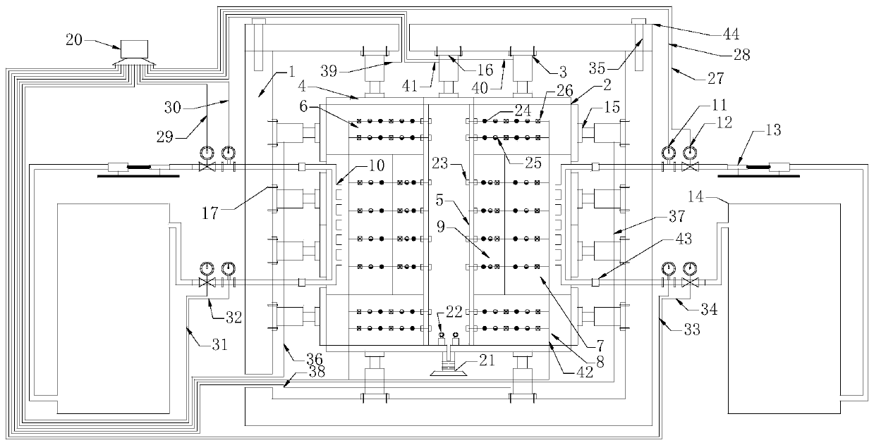
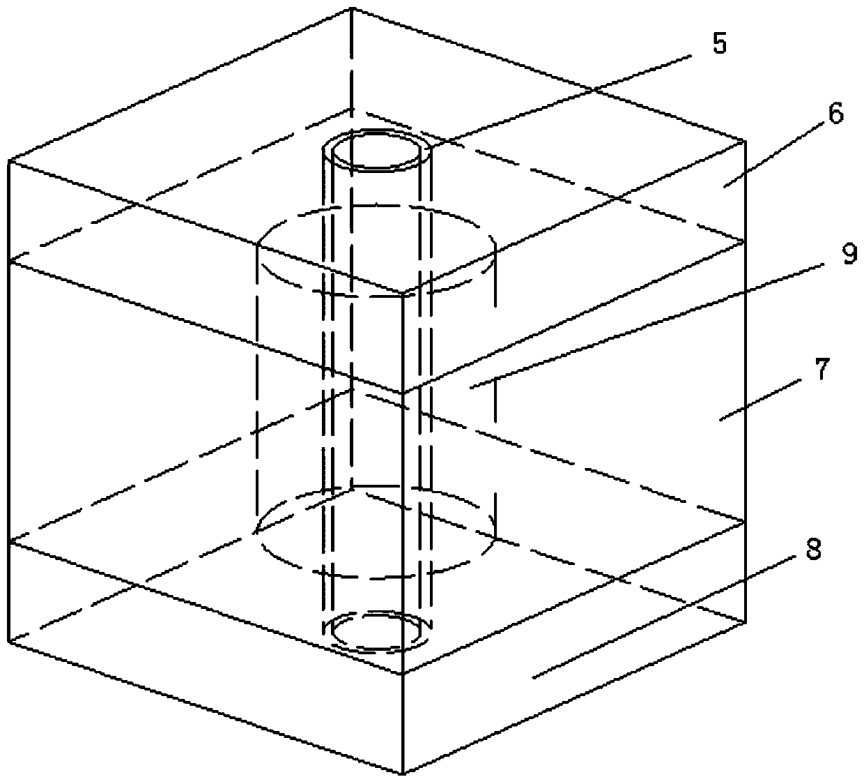
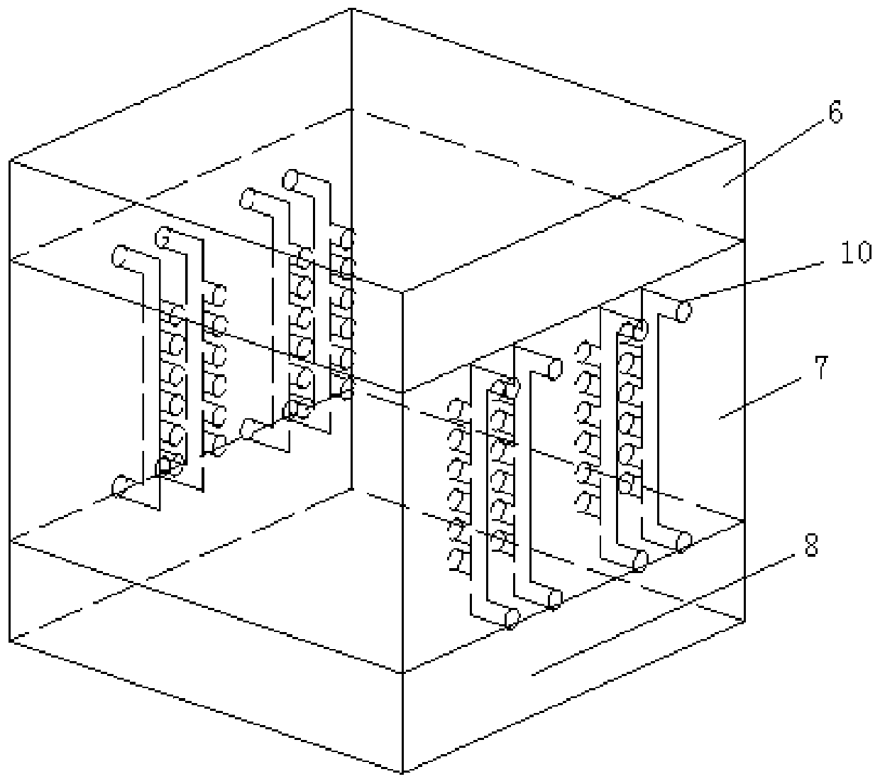
The invention discloses a simulation test device for a borehole wall bearing characteristic under a hydro-mechanical coupling function, comprising a simulation rock, a loading system, a seepage fieldcontrol system, a data acquisition system and a master controller; wherein the master controller is connected with the loading system, the seepage field control system and the data acquisition system.Through adoption of the simulation test device of the invention, a horizontal loading force, a vertical loading force, a concrete borehole wall axial loading force and a seepage water pressure are applied to the simulation rock, then space-time evolution laws of various physical fields are monitored by a monitoring component in a test process, and a series of on-site and laboratory parameters such as physical and mechanical properties and formation stress conditions of the concrete borehole wall, a curtain grouting body, a roof water-resisting layer, an aquifer and a bottom water-resisting layer are obtained, and similar simulation test research of ultimate bearing capacity and rheological fracture of the concrete borehole wall under the hydro-mechanical coupling function is performed, soas to obtain a time-based attenuation law of the ultimate bearing capacity of the concrete borehole wall under the hydro-mechanical coupling function.
Description
technical field [0001] The invention relates to the field of civil engineering, in particular to a simulation test device and method for the bearing characteristics of a well wall under hydraulic coupling. Background technique [0002] With the development of my country's construction industry, more and more large-scale deep mine roadways and long and deep buried tunnel projects are built in places with complex geological conditions, especially in bedrock sections under hydraulic coupling. In large-scale deep mine roadways and long and deep-buried tunnel projects under the action of hydraulic coupling, rheological fracture disasters may occur, causing casualties and economic losses, and may also cause irreparable huge losses to the entire project. [0003] Since the hydraulic coupling effect brings great hidden dangers to the deep mine roadway and deep buried tunnel engineering, in order to study the ultimate bearing capacity and rheological fracture of the concrete shaft wa...
Claims
Login to View More Application Information
Patent Timeline
 IPC IPC(8): G01N3/12
CPCG01N3/12
Inventor赵延林李阳廖健
OwnerHUNAN UNIV OF SCI & TECH