Frame structure of infrared touch screen, infrared touch screen and infrared touch equipment

An infrared touch screen and frame technology, which is applied in the input/output process of data processing, instruments, electrical digital data processing, etc., can solve the problems of positioning, the small number of infrared transceivers, and the reduction of the touch accuracy of the infrared touch screen. Improve the effect of touch precision

Pending Publication Date: 2019-11-12
GUANGZHOU HUAXIN ELECTRONICS TECH
View PDF8 Cites 2 Cited by
  • Summary
  • Abstract
  • Description
  • Claims
  • Application Information

AI Technical Summary

Problems solved by technology

[0003] The existing infrared touch screen is limited by the cost, the number of infrared transceiver devices set on the frame is small, the density of the formed infrared detection optical network is low, and the touch accuracy is not high; The infrared transceiver device emits and receives on-axis light, and calculates the position of the touch coordinates through the missing light in the X and Y directions. When the touch object is small in size and is located inside the grid of the infrared detection optical network, the X and Y directions There is no infrared light blocked on the optical network on the screen, and the processor inside the infrared touch device cannot locate the coordinate position according to the missing infrared detection light, resulting in the unrecognizable touch object, and the touch accuracy of the infrared touch screen is greatly reduced.

Method used


Image

  • Frame structure of infrared touch screen, infrared touch screen and infrared touch equipment
  • Frame structure of infrared touch screen, infrared touch screen and infrared touch equipment
  • Frame structure of infrared touch screen, infrared touch screen and infrared touch equipment

Examples


Embodiment Construction

[0026] The technical solutions in the embodiments of the present invention will be clearly and completely described below with reference to the accompanying drawings in the embodiments of the present invention. Obviously, the described embodiments are only a part of the embodiments of the present invention, but not all of the embodiments. Based on the embodiments of the present invention, all other embodiments obtained by those of ordinary skill in the art without creative efforts shall fall within the protection scope of the present invention.

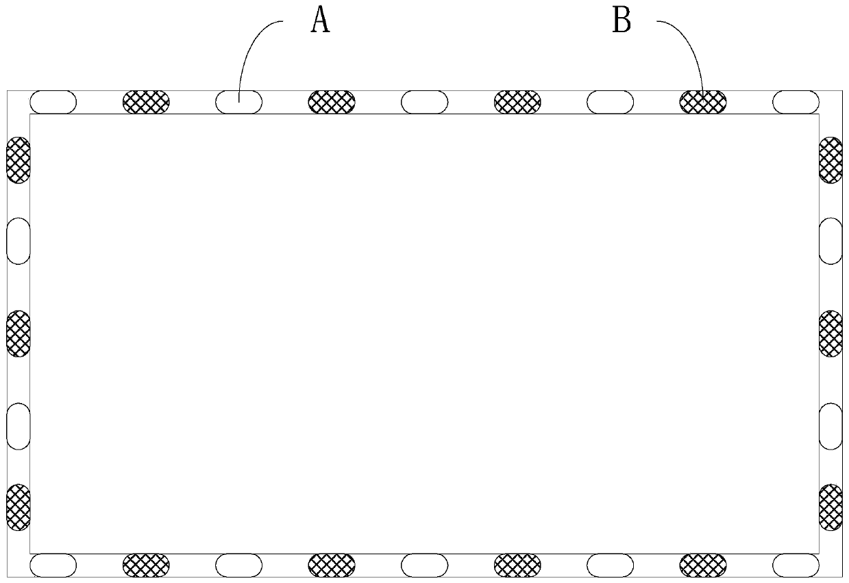
[0027] An embodiment of the present invention provides a frame structure of an infrared touch screen, please refer to figure 1 , is a schematic diagram of the frame structure of the infrared touch screen. In this embodiment, the frame body structure is rectangular, and each side bar is provided with a plurality of infrared emitting tubes A and a plurality of infrared receiving tubes B; wherein, The infrared emission tube A on each sid...


PUM


Abstract

The invention discloses a frame structure of an infrared touch screen. The frame structure comprises a frame body, a plurality of infrared transmitting tubes and a plurality of infrared receiving tubes, wherein the frame body is provided with four side strips; the infrared transmitting tubes are arranged on each side strip of the frame body, and the infrared receiving tubes are arranged on each side strip of the frame body; each infrared transmitting tube on each side edge strip of the frame body is configured to transmit three beams of infrared rays with different transmitting angles, and isused for transmitting one corresponding beam of infrared rays to one corresponding infrared receiving tube on each side edge strip of the other side edge strips; and each infrared receiving tube on each side edge strip of the frame body is used for receiving infrared rays emitted by one corresponding infrared emitting tube on each side edge strip of the other side edge strips. According to the frame structure of the infrared touch screen, the infrared touch screen and the infrared touch equipment disclosed by the embodiment of the invention, the cross-axis light and the counter-axis light aretransmitted and received through the infrared transmitting and receiving device, so that the optical network density and the touch precision are greatly improved.

Description

technical field [0001] The invention relates to the field of touch technology, in particular to a frame structure of an infrared touch screen, an infrared touch screen and an infrared touch device. Background technique [0002] With the continuous development of touch technology, infrared touch screens are widely used in various fields due to their advantages such as low production cost, convenient installation, and stable operation. The principle of the infrared touch screen is to emit and receive the detection light through the one-to-one corresponding infrared emitting tubes and infrared receiving tubes respectively installed on the two opposite sides of the touch frame to form a mesh light in the X and Y directions in the touch area. When there is a touch object in the touch area, a certain part of the light of the optical network is blocked, and then according to the subsequent signal sampling, the internal processor (such as MCU) locates the details of the touch object...

Claims


Application Information

Patent Timeline
IPC IPC(8): G06F3/041G06F3/042
CPCG06F3/0416G06F3/0421
Inventor 谢旺薛琛
Owner GUANGZHOU HUAXIN ELECTRONICS TECH
Why Eureka
Try Eureka