Boiler cleaning equipment
A boiler cleaning and equipment technology, which is applied to boiler cleaning devices, lighting and heating equipment, furnaces, etc., can solve the problems of inconvenient cleaning of the inner wall of the boiler and difficulty in cleaning equipment extending into it.
- Summary
- Abstract
- Description
- Claims
- Application Information
AI Technical Summary
Problems solved by technology
Method used
Image

Examples
Embodiment 1
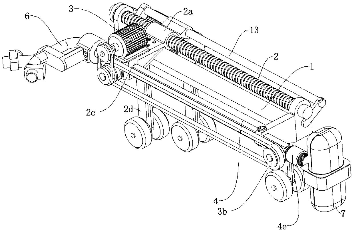
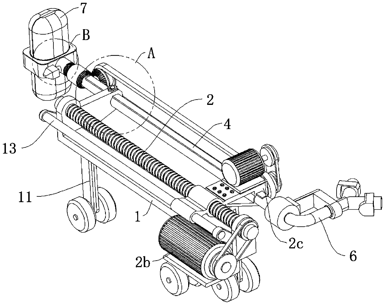
[0024] refer to Figure 1 to Figure 7 The shown boiler cleaning equipment includes a support 1, a traveling pipe 4 slidably supported on the support 1 along the horizontal direction, and an airbag assembly detachably connected to one end of the traveling pipe 4, the airbag assembly at least Including the air bag 7 communicated with the walking pipe 4, the end of the walking pipe 4 away from the air bag 7 communicates with the inflation device, before the air bag 7 moves into the boiler, the air bag 7 is in a contracted state, so that the air bag 7 is easy to enter the boiler, After the airbag 7 enters the boiler, the inflator inflates the airbag 7. The size of the airbag 7 after being filled with gas is equivalent to the size of the inner diameter of the boiler. Different boilers can use different sizes of the airbag 7. In addition, brushes are provided on at least the surface of the airbag 7 opposite to the inner surface of the boiler side wall, and the rotation of the airbag...
Embodiment 2
[0035] Such as Figure 8Shown, this embodiment has increased spherical nozzle 9 on the basis of embodiment one, and spherical nozzle 9 is in order to spray water or cleaning agent in boiler so that airbag 7 can achieve better before airbag 7 brushes the inner wall of boiler. scrubbing effect.
[0036] Specifically, one side of the spherical spray head 9 is provided with a second connecting piece 9a, and the shape of the second connecting piece 9a is the same as that of the first connecting piece 7b. The air bag 7 and the spherical nozzle 9 are disassembled and installed on the connecting sleeve 4e in turn, so that the boiler can be scrubbed in a certain order. The spherical spray head 9 is provided with a plurality of small holes for evenly spraying the liquid onto the inner wall of the boiler.
[0037] Further, in order to avoid or reduce residual liquid such as water or cleaning agent from entering into the air bag, a partition 4b is arranged in the mediation tube 4, and t...
PUM
 Abstract
Description
Claims
Application Information
 - R&D Engineer
- R&D Manager
- IP Professional
- Industry Leading Data Capabilities
- Powerful AI technology
- Patent DNA Extraction
Browse by: Latest US Patents, China's latest patents, Technical Efficacy Thesaurus, Application Domain, Technology Topic.
© 2024 PatSnap. All rights reserved.Legal|Privacy policy|Modern Slavery Act Transparency Statement|Sitemap