Telescopic side-tearing cover assembly

A cover assembly and rod technology, which is applied to the device for preventing the repeated filling of the container, the locking device, the closing, etc., can solve the problems of high assembly and manufacturing costs, poor sealing performance, and unsatisfactory sealing performance, and achieve convenient operation. , smooth liquid discharge, good sealing effect

Pending Publication Date: 2019-11-22
ZHONGSHAN HUABAOLE DAILY NECESSITIES IND CO LTD
View PDF0 Cites 0 Cited by
  • Summary
  • Abstract
  • Description
  • Claims
  • Application Information

AI Technical Summary

Problems solved by technology

In the prior art, there is an inner cover / plug directly made of silica gel. However, when using this structure, the inner cover / plug needs to be removed. In the process of removing the inner cover / plug, there is a seal after opening and using. poor performance
[0003] In addition, there is also an inner cover structure, which is formed by connecting multiple components, but it has the disadvantages of high assembly and manufacturing costs, and poor liquid discharge effect during use, and also has the defect of unsatisfactory sealing performance after opening and using

Method used


Image

  • Telescopic side-tearing cover assembly
  • Telescopic side-tearing cover assembly
  • Telescopic side-tearing cover assembly

Examples


Embodiment 1

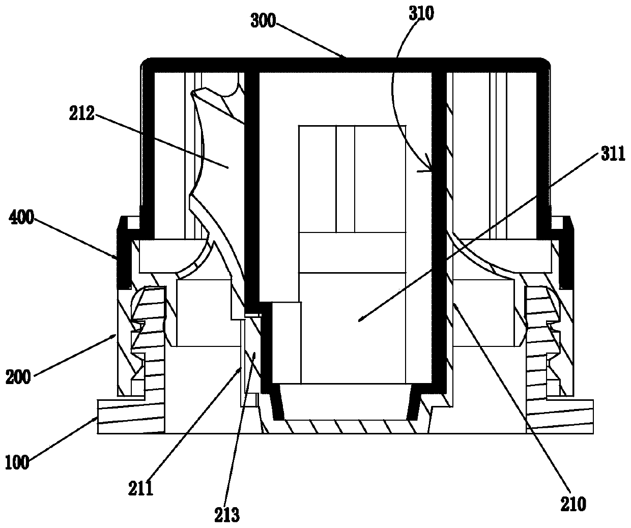
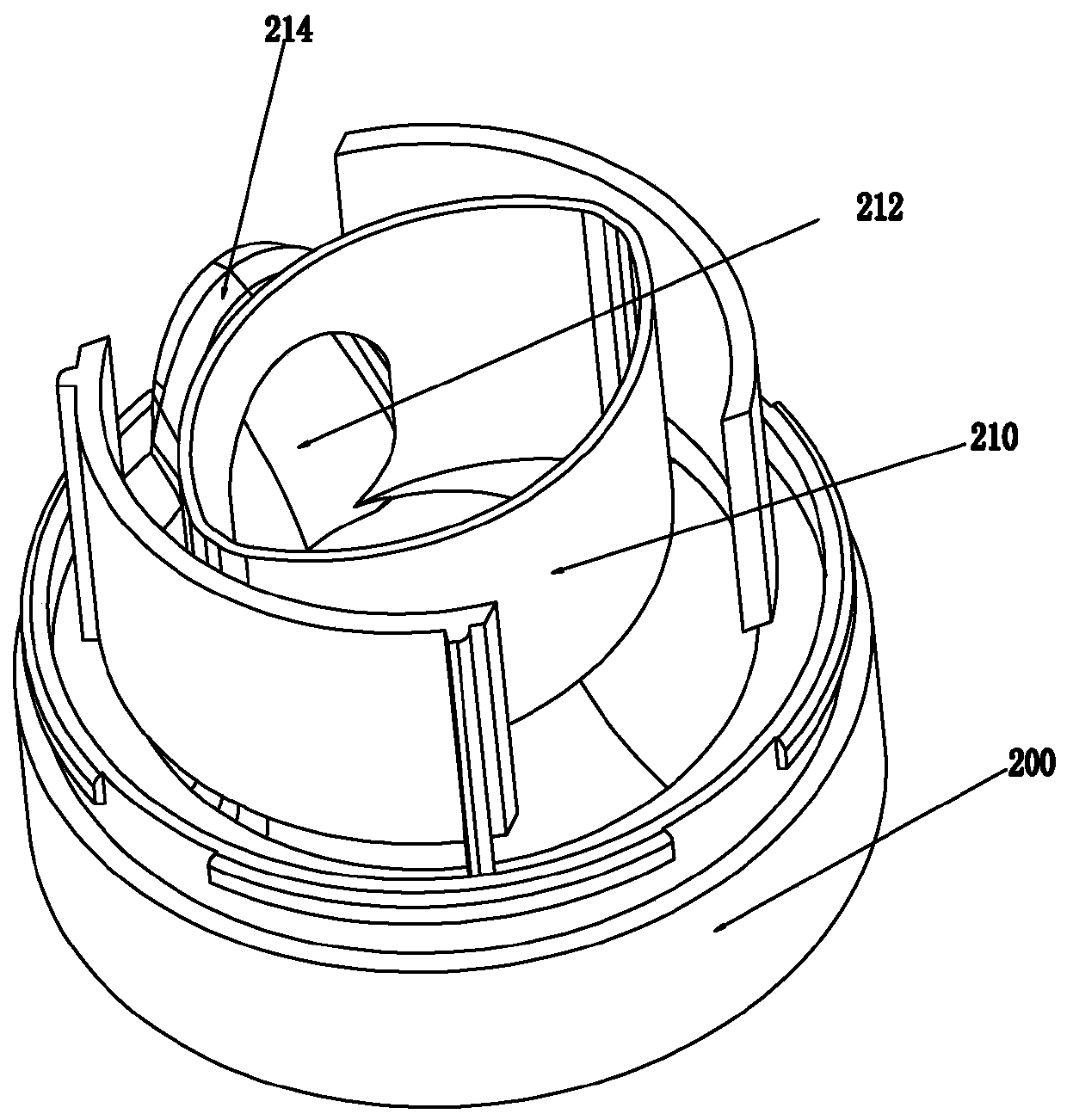
[0030] Such as Figure 1-6 As shown, a retractable side-tearable lid assembly of the present invention includes a base 200 for connecting with the mouth of the container body 100, the inner wall of the base 200 extends toward the center to form a liquid outlet column 210, and the liquid outlet column 210 It is hollow and has an open end and a sealed end. The open end of the liquid outlet column 210 is set opposite to the sealed end of the liquid outlet column 210. The sealed end of the liquid outlet column 210 extends toward the inner cavity of the container body 100. The liquid outlet column 210 is sealed A liquid outlet 211 is provided on the side wall of the end, a liquid outlet sleeve 212 is provided on the side wall of the opening end of the liquid outlet column 210, and an upper cover 300 that covers the opening end of the liquid outlet column 210 is connected to the base 200 , the inner bottom of the upper cover 300 is extended to form a rod 310 that extends into the in...

Embodiment 2

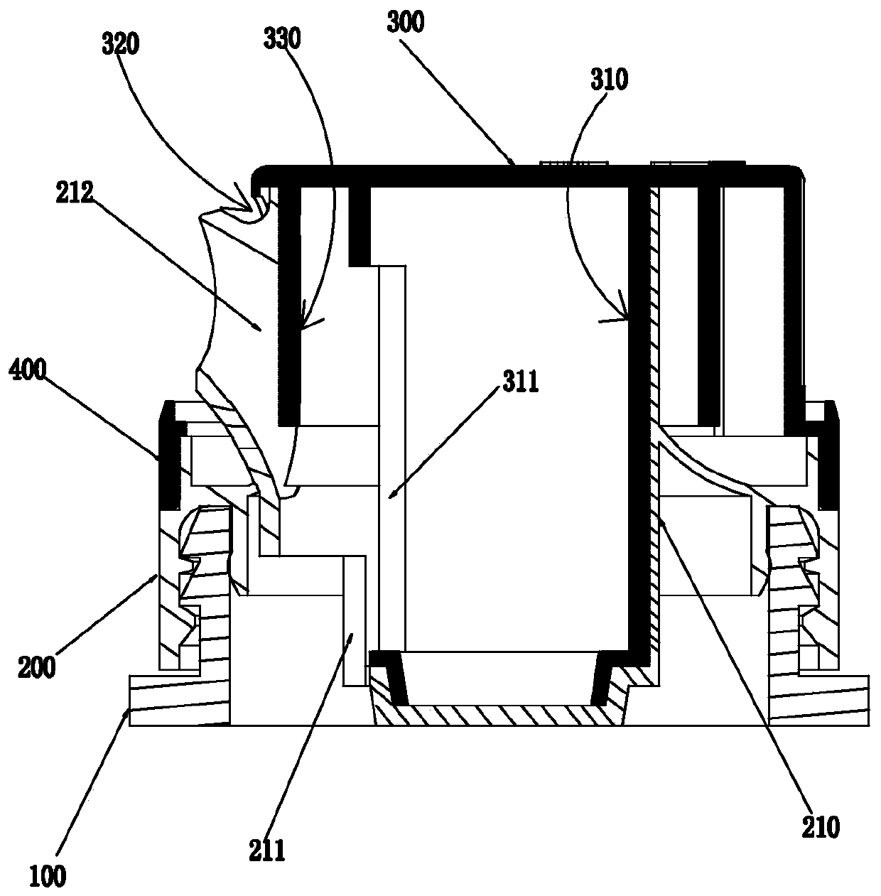
[0036] Embodiment 2: as Figure 7 As shown, in order to provide multiple ways of use and meet the different needs of users, the number of the liquid outlet sleeve 212 is two, and the two liquid outlet sleeves 212 are oppositely arranged on the side wall of the opening end of the liquid outlet column 210 , the upper cover 300 is correspondingly provided with two liquid outlet windows 320 for use with the two liquid outlet sleeves 212, and the rod member 310 is correspondingly provided with two rod member liquid outlets for use with the two liquid outlet sleeves 212. Mouth 311. When in use, one liquid outlet sleeve is used to pour out the substance, and an air inlet channel is formed relative to the other liquid outlet sleeve, so that a channel is formed between the liquid outlet sleeve and the inner cavity of the container body so that the liquid filled in the inner cavity of the container body The substance can be quickly poured out.

[0037] Such as figure 1 , 2 , 5 and 6...

Embodiment 3

[0044] Such as Figure 8 As shown, the difference between Embodiment 3 and Embodiment 1 is that Embodiment 3 changes the liquid outlet sleeve 212 of Embodiment 1 into a liquid nozzle.

[0045] The rest of the structure of embodiment 3 is the same as that of embodiment 1.


PUM


Abstract

The invention discloses a telescopic side-tearing cover assembly. The cover assembly comprises a base and an upper cover; and a user acts on the upper cover to enable a rod piece to move relative to aliquid outlet column, so that a liquid outlet of the rod piece communicates with a liquid outlet sleeve, and the liquid outlet sleeve is aligned to a liquid outlet window to enable an inner cavity ofa container body to communicate with the outside, and at the moment, the user can pour substances injected in the inner cavity of the container body out of the liquid outlet sleeve. Therefore, the telescopic side-tearing cover assembly is characterized by being good in sealing performance, smooth in liquid outlet and convenient to operate; and the substances in the inner cavity of the container body can be poured out without separating the upper cover from the base, so that the cover assembly is clean and sanitary.

Description

【Technical field】 [0001] The invention relates to a container closure, in particular to a retractable side-tearable lid assembly. 【Background technique】 [0002] Corresponding to some packaging such as containers, it needs to use an inner cover, that is, install the inner cover at the mouth of the container and then connect the outer cover. In the prior art, there is an inner cover / plug directly made of silica gel. However, when using this structure, the inner cover / plug needs to be removed. In the process of removing the inner cover / plug, there is a seal after opening and using. Problem with poor performance. [0003] In addition, there is also an inner cover structure, which is formed by connecting multiple components, but it has the disadvantages of high assembly and manufacturing costs, poor liquid discharge effect during use, and unsatisfactory sealing performance after opening and using. [0004] For this reason, how to provide a container closure with good sealing p...

Claims


Application Information

Patent Timeline
Patent Type & Authority Applications(China)
IPC IPC(8): B65D47/36B65D47/06B65D55/02B65D53/00B65D49/12
CPCB65D47/06B65D47/36B65D49/12B65D53/00B65D55/02B65D2251/06B65D2251/20
Inventor 李红彪
Owner ZHONGSHAN HUABAOLE DAILY NECESSITIES IND CO LTD
Why Eureka
Try Eureka