
A vertical scraper center discharge filter centrifuge

A center discharge and centrifuge technology, applied in centrifuges and other directions, can solve the problems of high modification costs, environmental pollution, and high labor intensity.

Active Publication Date: 2021-05-11
浙江诚铭机械有限公司
View PDF10 Cites 0 Cited by
  • Summary
  • Abstract
  • Description
  • Claims
  • Application Information

AI Technical Summary

Problems solved by technology

[0003] At present, the domestic pharmaceutical and chemical industries use a large number of low-cost, backward-technical three-legged or flat-plate manual unloading centrifuges, which are labor-intensive and prone to cross-contamination between people and materials, and environmental pollution is difficult to control. Due to the existing automatic Unloading centrifuges such as: vertical scraper centrifuge, horizontal scraper centrifuge, vertical hanging bag centrifuge, flipping bag centrifuge, etc. cannot be replaced without changing the original workshop structure. The improvement of the structure and the installation space of the equipment will inevitably affect the whole body. The modification cost is very high and the transformation period is long, so the old workshop has not been able to change the backward situation of the equipment.

Method used


Image

  • A vertical scraper center discharge filter centrifuge
  • A vertical scraper center discharge filter centrifuge
  • A vertical scraper center discharge filter centrifuge

Examples


Embodiment Construction

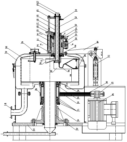
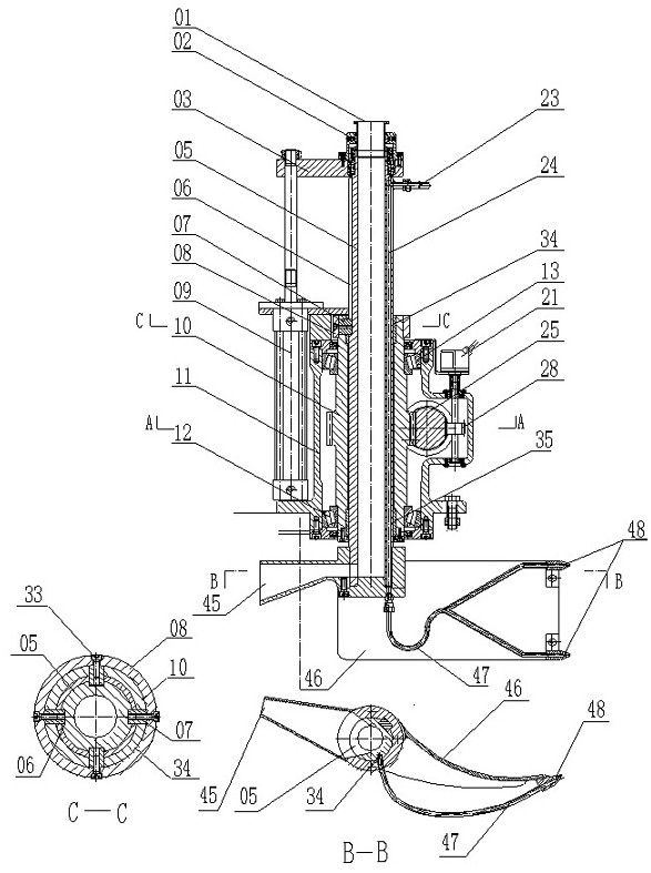
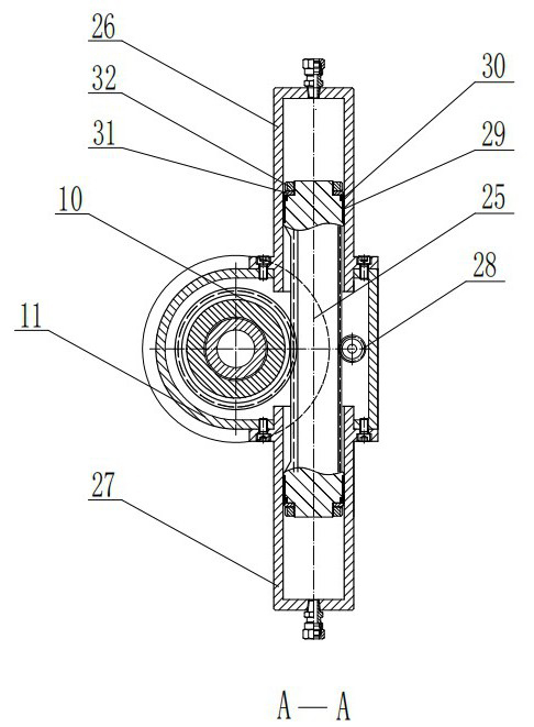
[0037] Below in conjunction with accompanying drawing, the present invention will be further described with specific embodiment, see figure 1 — Figure 11 :

[0038] A vertical scraper center discharge filter centrifuge; including a fixed shaft 20 fixed by the main shaft, the shaft hole of the fixed shaft 20 is a discharge channel, the fixed shaft 20 is connected to the flange seat 19 and installed on the base plate 22. The bearing outer drum 16 is installed on the fixed shaft 20 through the bearings 15 and 17. The bearing outer drum 16 is connected to the rotating drum 38 and fastened with the inner hexagon screw 14. There is a belt groove 43 on the bearing outer drum 16, and the motor 42 passes through the pulley. 41. The transmission belt 40 drives the bearing outer drum 16 and the rotating drum 38 to rotate, and the scraper bar 05 moves up and down and rotates. Air knife integrated structure sees B-B view), pusher plate 46, air pipe 47, cloth opening 45 functions.

[0...


PUM


Abstract

The invention belongs to solid-liquid separation equipment, and relates to a vertical scraper central discharge filter centrifuge, which includes a fixed shaft fixed by a main shaft, and the shaft hole of the fixed shaft serves as a discharge channel. The fixed shaft is connected on the flange seat and installed on the base plate. The bearing outer drum is connected with the drum, and there is a belt groove on the bearing outer drum, and the motor passes through the pulley, and the transmission belt drives the bearing outer drum and the drum to rotate. The upper end of the scraper bar is the feeding port, and the up and down reciprocating motion is driven by a vertical oil cylinder. The scraper rod rotation device is composed of gear shaft, bearing, double-headed piston gear rod, oil cylinder liner and casing. The double-headed piston gear rod is driven by the hydraulic cylinder to drive the gear shaft to rotate, and the gear shaft drives the scraper rod to rotate through the slider. The shaft of the pinion is connected to the encoder to output the angular position signal required by the scraper, air knife, pusher plate, and cloth opening, which is automatically controlled by the electronic control system and executed by the hydraulic system. It is suitable for solid state in the pharmaceutical and chemical industry liquid separation.

Description

technical field [0001] The invention belongs to the technical field of solid-liquid separation equipment in the pharmaceutical and chemical industries, and particularly refers to a vertical scraper unloading mechanism for unloading a filter centrifuge from a center hole of a fixed shaft. Background technique [0002] In the fields of pharmaceutical and chemical manufacturing, solid-liquid separation centrifuges are widely used separation equipment, all of which are named after the discharge method, such as three-legged manual discharge centrifuge, flat plate manual discharge centrifuge, horizontal scraper centrifuge , Vertical scraper pull bag centrifuge, vertical hanging bag centrifuge, flip bag centrifuge, vertical scraper bottom discharge centrifuge, etc. [0003] At present, the domestic pharmaceutical and chemical industries use a large number of low-cost, backward-technical three-legged or flat-plate manual unloading centrifuges, which are labor-intensive and prone to ...

Claims


Application Information

Patent Timeline
Patent Type & Authority Patents(China)
IPC IPC(8): B04B11/08
CPCB04B11/08
Inventor 张嗣远潘万贵张鹤鸣
Owner 浙江诚铭机械有限公司
Learn More