Frequency discrimination method and frequency discrimination device for positioning base station time hopping signals

A technology for positioning base stations and time-hopping, which is applied to measurement devices, satellite radio beacon positioning systems, instruments, etc., and can solve the problem that time-hopping signal application scenarios cannot be effectively applied, signals are identified, and the tolerance range of initial Doppler estimation errors is small. And other issues

Active Publication Date: 2019-11-26
TSINGHUA UNIV
View PDF21 Cites 1 Cited by
  • Summary
  • Abstract
  • Description
  • Claims
  • Application Information

AI Technical Summary

Problems solved by technology

[0003] The pseudolite system basically uses the direct sequence spread spectrum signal of the traditional GNSS system, but due to the relatively large difference between the distance between the user and each pseudolite in the pseudolite system, there may be serious near-far effect problems, so that it is impossible to rely solely on the code To identify weaker signals by means of division multiple access, the pseudolite system introduces a time-hopping pulse transmission mechanism on the basis of traditional GNSS signals, that is, it uses the so-called direct sequence spread spectrum-time-hopping signal (TH-DSSS ) signal system
[0004] The TH-DSSS time-hopping signal system adopted by the pseudolite system solves the problem of the near-far effect of the pseudolite system itself. However, it is precisely because of the time-hopping pulse characteristics of the TH-DSSS time-hopping signal system that when tracking the received signal carrier In the frequency locked loop, if the traditional frequency discrimination scheme is directly adopted, there will be problems such as weak initial traction force of the loop and small tolerance range for the initial Doppler estimation error during the signal carrier tracking process, and even in a certain In some cases it may not be possible to track the signal
It can be seen that the existing traditional frequency discrimination schemes cannot effectively apply to the application scenarios of time-hopping signals, so it is necessary to design a frequency discrimination scheme suitable for the application scenarios of time-hopping signals

Method used


Image

  • Frequency discrimination method and frequency discrimination device for positioning base station time hopping signals
  • Frequency discrimination method and frequency discrimination device for positioning base station time hopping signals
  • Frequency discrimination method and frequency discrimination device for positioning base station time hopping signals

Examples


Embodiment Construction

[0015] The method and device for frequency discrimination of time-hopping signals disclosed in the present application will be described in detail below with reference to the accompanying drawings. For the sake of brevity, in the description of the various embodiments of the present application, the same or similar devices use the same or similar reference numerals.

[0016] Based on the time-hopping signal model of the positioning base station, the time-hopping signal frequency discrimination scheme of the present application is described below by analyzing the time-hopping characteristics of the time-hopping signal. The positioning base station in this application may be, for example, a pseudolite, a ground-based positioning base station and / or a wireless beacon.

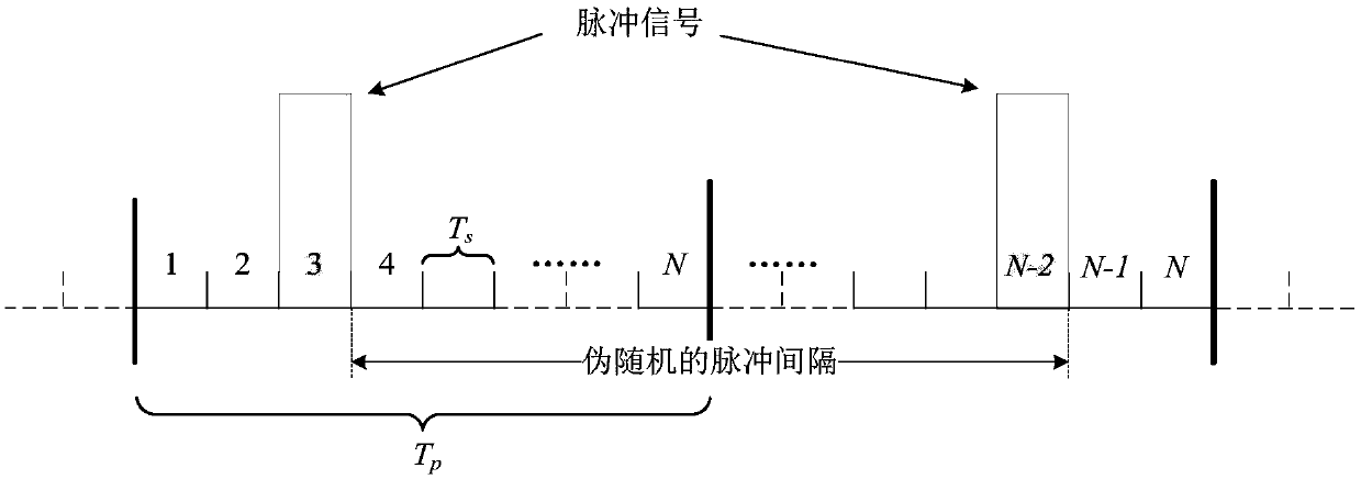
[0017] figure 1 An example of a direct sequence spread spectrum pulse signal transmitted by a positioning base station in a positioning base station system using TH-DSSS time-hopping signal system is shown. Such...


PUM


Abstract

The invention provides a frequency discrimination method for positioning base station time hopping signals. The frequency discrimination method comprises the following steps: calculating a frequency error of a local recurrence time hopping signal according to an interval between adjacent time hopping pulses in the time hopping signal. The invention further provides a frequency discrimination device for positioning base station time hopping signals. According to the frequency discrimination method and the frequency discrimination device for positioning base station time hopping signals providedby the invention, the time hopping characteristic of a time hopping signal is fully used, and the frequency error of the local recurrence time hopping signal can be obtained according to the characteristics of the time hopping signal. Thus, the convergence speed of the frequency locking loop can be increased, the initial traction force of the frequency locking loop is effectively enhanced in thetime hopping signal carrier tracking process, and the tolerance range of the frequency locking loop to initial Doppler estimation errors can be widened.

Description

technical field [0001] The application relates to a frequency discrimination method and a frequency discrimination device for locating base station time-hopping signals. Background technique [0002] The navigation satellites in the traditional satellite navigation system (GNSS) use direct sequence spread spectrum (DSSS) signals, and the satellites transmit signals simultaneously on the same frequency carrier in the form of code division multiple access multiplexing (CDMA) by using different spreading codes . In the process of tracking the carrier of the received signal, the frequency difference between the carrier of the received signal and the carrier of the local reproduced signal is identified through the frequency locking loop, and the carrier frequency of the local reproduced signal is adjusted according to the frequency difference Carry out dynamic adjustment, and after multiple cycles of feedback, the carrier frequency of the received signal is finally dynamically c...

Claims


Application Information

Patent Timeline
Patent Type & Authority Applications(China)
IPC IPC(8): G01S19/24
CPCG01S19/24
Inventor 姚铮运世洁陆明泉
Owner TSINGHUA UNIV
Why Eureka
Try Eureka