A dust removal device for textile processing

A technology of dust removal device and dust outlet pipe, which is applied in the direction of cleaning device, textile and paper making, transportation and packaging, etc. It can solve the problems of inconvenient maintenance and cleaning, inconvenient cleaning, inconvenient adjustment of the angle of the wind direction plate, etc., so as to reduce manpower consumption and facilitate cleaning Effect

Active Publication Date: 2021-08-31
沅江瑞鸿服饰有限公司
View PDF13 Cites 0 Cited by
  • Summary
  • Abstract
  • Description
  • Claims
  • Application Information

AI Technical Summary

Problems solved by technology

[0004] The purpose of the present invention is to provide a kind of dedusting device for textile processing, to solve the problem that the dedusting device for textile processing in the market currently on the market proposed by the above-mentioned background technology is inconvenient to clean up pollutants such as dust and cotton wool on the surface of textiles, and the dedusting device for textile processing is not easy to clean. It is convenient to adjust the angle of the wind direction plate. The dust removal device for textile processing is not convenient to adjust the distance between the conveyor belt and the wind direction plate. The dust removal device for textile processing is not convenient for cleaning the dust and other pollutants inside the device. The problem that it is not convenient to maintain and clean the dust removal device for dust collection and textile processing

Method used


Image

  • A dust removal device for textile processing
  • A dust removal device for textile processing
  • A dust removal device for textile processing

Examples


Embodiment Construction

[0029] The following will clearly and completely describe the technical solutions in the embodiments of the present invention with reference to the accompanying drawings in the embodiments of the present invention. Obviously, the described embodiments are only some, not all, embodiments of the present invention. Based on the embodiments of the present invention, all other embodiments obtained by persons of ordinary skill in the art without making creative efforts belong to the protection scope of the present invention.

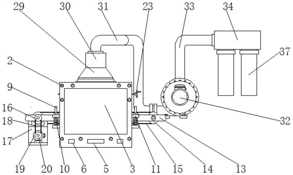
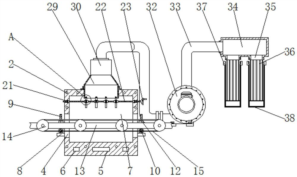
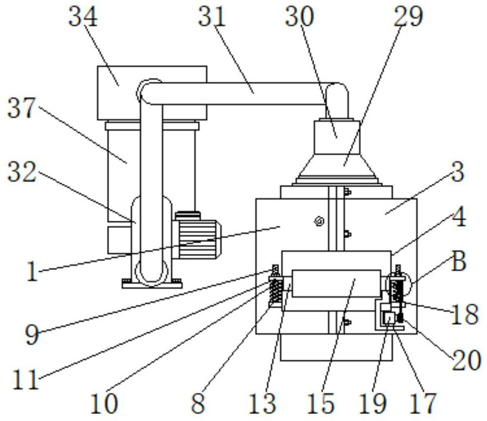
[0030] see Figure 1-6 , the present invention provides a technical solution: a dust removal device for textile processing, including a first box body 1, bolts 2, a second box body 3, a through hole 4, a first square groove 5, a second square groove 6, a box Wall 7, support plate 8, threaded column 9, spring 10, connection seat 11, nut 12, fixed frame 13, roller 14, transmission belt 15, first pulley 16, motor frame 17, belt 18, motor 19, second pulley 20. Be...


PUM


Abstract

The invention discloses a dust removal device for textile processing, which comprises a first box body, a spring and a fixing frame. Bolts are arranged on the outer edge of the first box body, and one side of the first box body is connected by bolts. The second box body, wherein, the two sides of the first box body and the second box body are provided with through holes, the spring is connected with the threaded column, and the fixing frame penetrates the first box body and the second box body through the connecting seat. Inside the second box, bearing seats are provided at both ends inside the first box, threaded rods are connected inside the bearing seats, and threaded sleeves are connected outside the threaded rods. The dust removal device for textile processing is provided with a threaded rod, and the threaded rod is driven to rotate in the bearing seat by rotating the turntable, so that the threaded sleeve on the threaded rod can move left and right, and the moving threaded sleeve moves in the chute hole through the cylindrical rod. to drive the wind direction plate to rotate around the rotating shaft in the suction funnel, so as to facilitate the adjustment of the angle of the wind direction plate.

Description

technical field [0001] The invention relates to the technical field of dust removal in textile processing, in particular to a dust removal device for textile processing. Background technique [0002] Energy saving and emission reduction is the future development trend. The textile industry has been criticized for its high pollution and non-environmental protection, which is not conducive to the development of the industry. Environmental pollution has become a bottleneck for the development of the industry. During the textile processing process, textile processing equipment will generate excessive dust pollution. In order to improve the environment in the textile processing workshop, we have higher and higher requirements for the dust removal device for textile processing. We hope that through the innovation of the dust removal device for textile processing, the working efficiency of the dust removal device for textile processing can be improved, the working hours can be reduc...

Claims


Application Information

Patent Timeline
Patent Type & Authority Patents(China)
IPC IPC(8): B65G45/10D06G1/00
CPCB65G45/10D06G1/00
Inventor 吴永金
Owner 沅江瑞鸿服饰有限公司
Why Eureka
Try Eureka