Waterway switching structure and water outlet switching device of combined shower

A waterway and water outlet technology, applied in the field of sanitary ware, can solve the problems of large switching force, bad hand feeling, and inability to achieve water pressure balance, etc., and achieve the effect of small switching force and good hand feeling

Active Publication Date: 2019-12-03
ZHANGZHOU SOLEX SMART HOME CO LTD
View PDF4 Cites 2 Cited by
  • Summary
  • Abstract
  • Description
  • Claims
  • Application Information

AI Technical Summary

Problems solved by technology

Traditional switching valves mostly use pilot valves, which cannot achieve water pressure balance when switching, resulting in a bad switching feel and a large force required for switching
If you want to press the pressure value to be small, the pressure relief hole of the pilot valve must be made very small, and when the pressure relief hole is small, it is difficult to make the switching valve into a pressing structure

Method used


Image

  • Waterway switching structure and water outlet switching device of combined shower
  • Waterway switching structure and water outlet switching device of combined shower
  • Waterway switching structure and water outlet switching device of combined shower

Examples


Embodiment 1

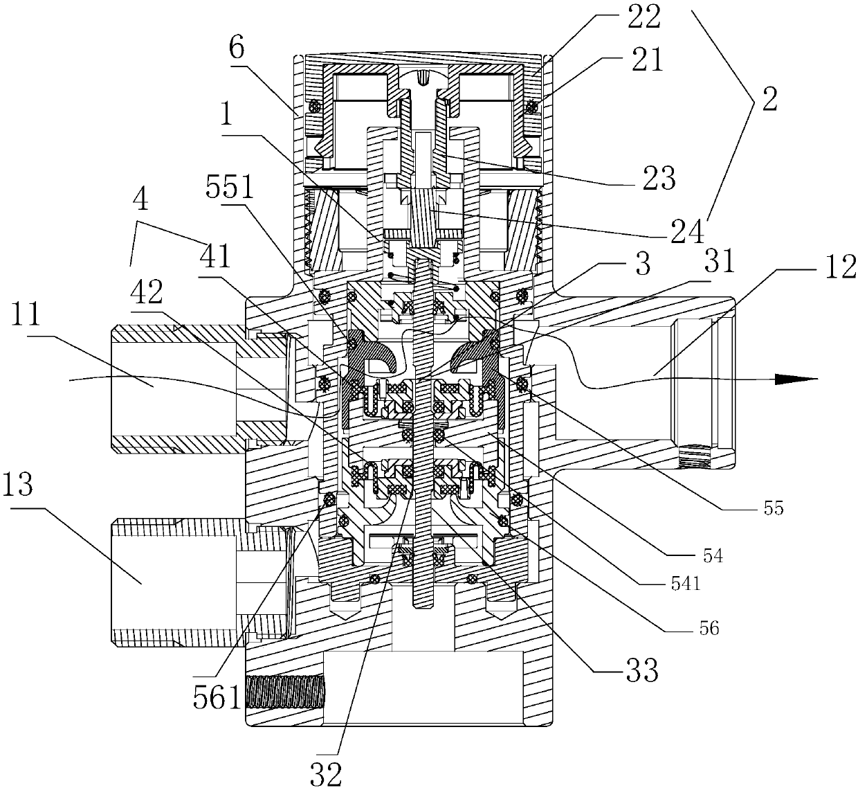
[0057] refer to figure 1 , a structure for switching waterways, comprising: a body 1, a switching operation part 2, a switching part 3, a sealing part 4, a water diversion part and a casing 6, and the body 1 is placed in the casing 6;

[0058] The body 1 has a water inlet 11, a first water outlet 12, and a second water outlet 13; the switching operation part 2 is provided in conjunction with the switching part 3, and the switching part 3 is sequentially provided with a first water outlet along its own moving direction. The first pressure relief member 31, the linkage 32 and the second pressure relief member 33; the shell 6 has openings at the positions corresponding to the water inlet 11, the first water outlet 12, and the second water outlet 13, and the water flow flows from the water inlet to the water outlet. When the first water outlet or the second water outlet flows, it will not flow to the area between the casing 6 and the body 1 .

[0059] The water distribution membe...

Embodiment 2

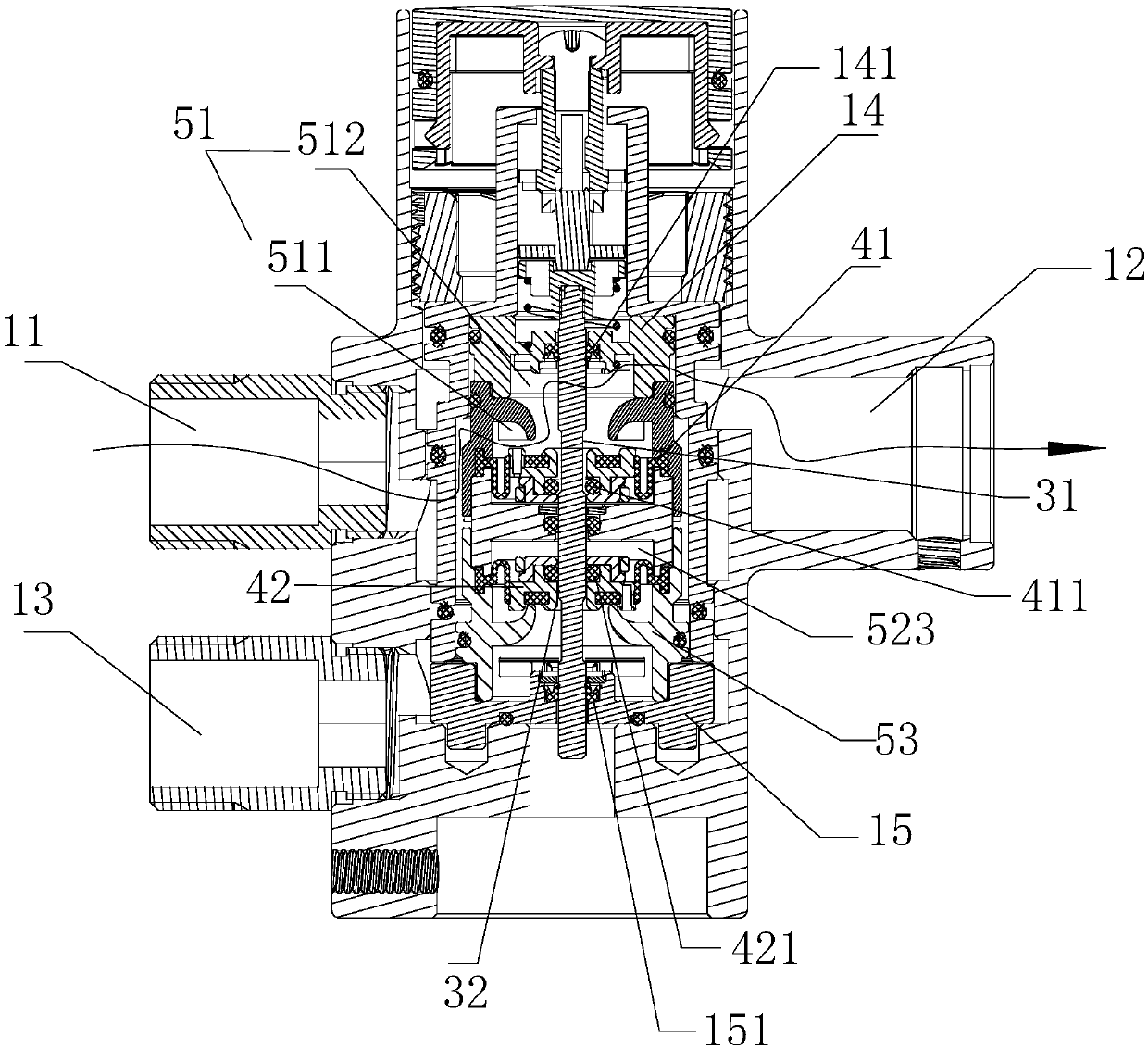
[0079] The difference between this embodiment and embodiment 1 is: as Figure 4 As shown, the lower sealing seat 15 is canceled, so that the lower water distribution seat 56 replaces the role of the lower sealing seat 15 . Because the size of the switching lever in this embodiment is very small, even if the lower sealing seat 15 is eliminated, the force required for pressing the switch is not too large, and the switching feel can still be ensured.

Embodiment 3

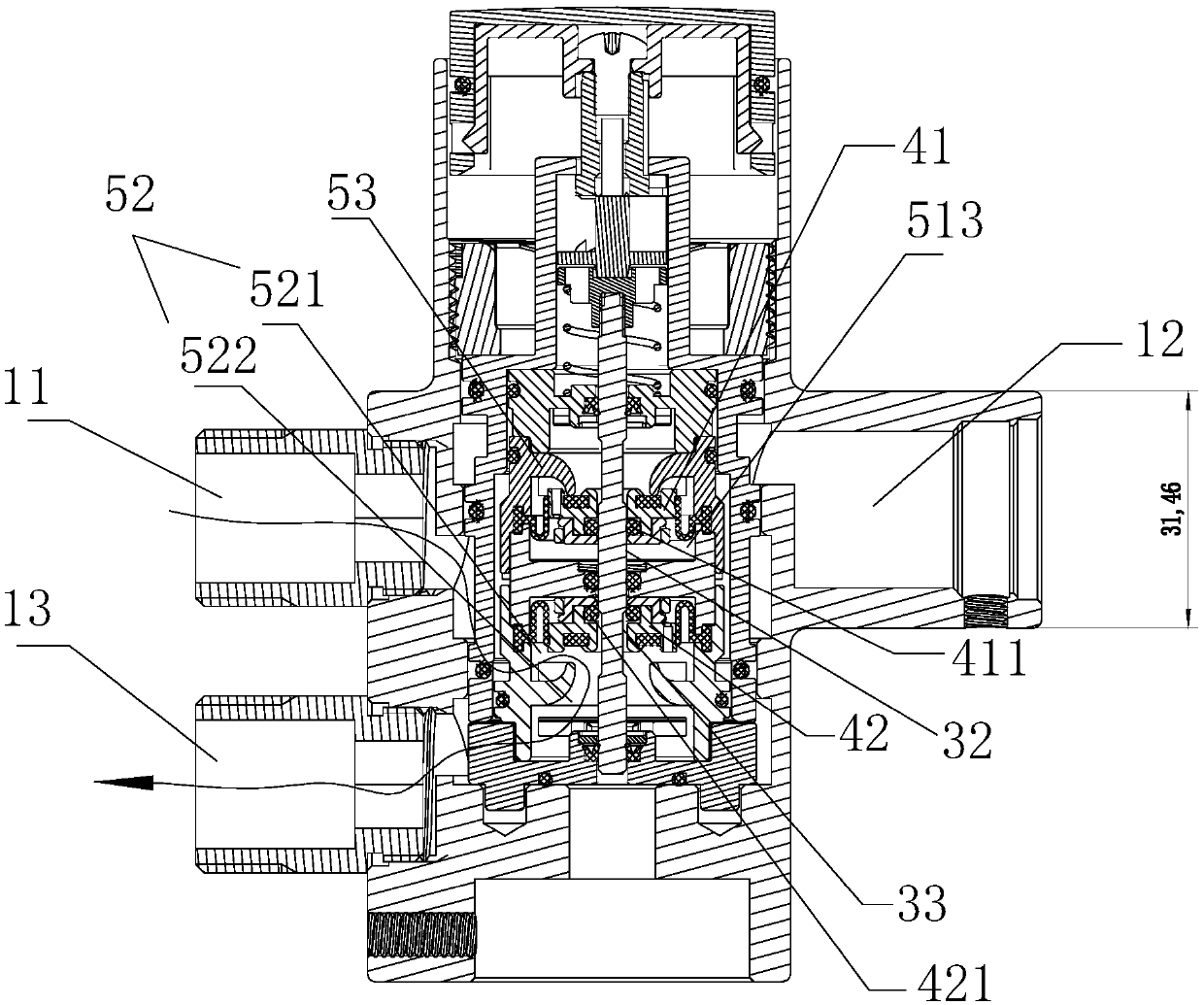
[0081] The difference between this embodiment and embodiment 1 is: refer to Figure 5 , not only the lower sealing seat 15 is canceled, but also the lower end of the switching member 3 is directly connected with a part of the main body 1 through the Y-shaped sealing ring 34 .


PUM


Abstract

The invention provides a waterway switching structure. A body is provided with a water inlet, a first water outlet and a second water outlet. A switching operation piece and a switching piece are arranged in a linkage mode, and the switching piece is sequentially provided with a first pressure relief piece, a linkage piece and a second pressure relief piece in the moving direction of the switchingpiece. A water distribution piece is arranged in the body and provided with two independent water distribution cavities, the two water distribution cavities are arranged up and down in the moving direction of the switching piece, and each water distribution cavity comprises a water inlet cavity communicated with the water inlet and a water outlet cavity communicated with the first water outlet orthe second water outlet; an upper sealing piece and a lower sealing piece are correspondingly arranged in the upper water distribution cavity and the lower water distribution cavity respectively, theupper sealing piece and the lower sealing piece further form a pressure forming cavity in the upper water distribution cavity and the lower water distribution cavity, and the pressure forming cavityis provided with a normal opening communicated with the water inlet. According to the waterway switching structure provided by the invention, the force required for switching is relatively light, andthe switching hand feeling is good.

Description

technical field [0001] The invention relates to the field of sanitary ware, in particular to a waterway switching structure. Background technique [0002] In the bathroom industry, one valve is often used to control the water output of multiple water outlet terminals. For example, in the shower system, a switching valve is used to control the water output of the hand shower or overhead shower. Traditional switching valves mostly use pilot valves, which cannot achieve water pressure balance when switching, resulting in a bad switching feel and a large force required for switching. If you want to press the pressure value to be small, the pressure relief hole of the pilot valve must be made very small, and when the pressure relief hole is very small, it is difficult to make the switching valve into a pressing structure. Contents of the invention [0003] The main technical problem to be solved by the present invention is to provide a waterway switching structure, which requi...

Claims


Application Information

Patent Timeline
Patent Type & Authority Applications(China)
IPC IPC(8): F16K11/07F16K11/10F16K31/44F16K31/60
CPCF16K11/0712F16K11/10F16K31/44F16K31/605
Inventor 林方棋胡力宏魏志坚但堂俊
Owner ZHANGZHOU SOLEX SMART HOME CO LTD
Why Eureka
Try Eureka