Anti-jittering lens driving device

A lens driving device and anti-shake technology, applied in focusing devices, projection devices, printing devices, etc., can solve the problems of difficult assembly, large product volume, conflicting requirements for small volume, etc., and achieve simple structure, good imaging effect, compensation hand shaking effect

Pending Publication Date: 2019-12-06
安庆市东勤电子科技有限公司
View PDF0 Cites 2 Cited by
  • Summary
  • Abstract
  • Description
  • Claims
  • Application Information

AI Technical Summary

Problems solved by technology

[0003] The shaft-shifting optical anti-shake lens drive device performs tilting movement relative to the image sensor to realize the anti-shake function, and performs vertical movement relative to the image sensor to realize the auto-focus function, which can be realized by using a set of suspension system and electromagnetic force drive system; this This device has a simple structure, but due to the shifting movement of the lens, the surrounding imaging effect is poor, which does not match the high-quality imaging effect currently demanded by the market
[0004] The translational optical anti-shake lens drive device performs parallel movement relative to the image sensor to realize the anti-shake function, and performs vertical movement relative to the image sensor to realize the auto-focus function; the prior art generally uses two sets of independent suspension and electromagnetic force drive systems, At the same time, position sensors such as Hall elements are required to detect the moving direction and moving amount; this type of device has a very complex structure, many workpieces and high precision requirements for the workpieces, it is very difficult to assemble, the production efficiency and yield are very low, and the product volume is relatively large. Large, which conflicts with the small size requirements of mobile phones or portable camera equipment

Method used


Image

  • Anti-jittering lens driving device
  • Anti-jittering lens driving device
  • Anti-jittering lens driving device

Examples


Embodiment Construction

[0030] The following will clearly and completely describe the technical solutions in the embodiments of the present invention with reference to the accompanying drawings in the embodiments of the present invention. Obviously, the described embodiments are only some, not all, embodiments of the present invention. Based on the embodiments of the present invention, all other embodiments obtained by persons of ordinary skill in the art without making creative efforts belong to the protection scope of the present invention.

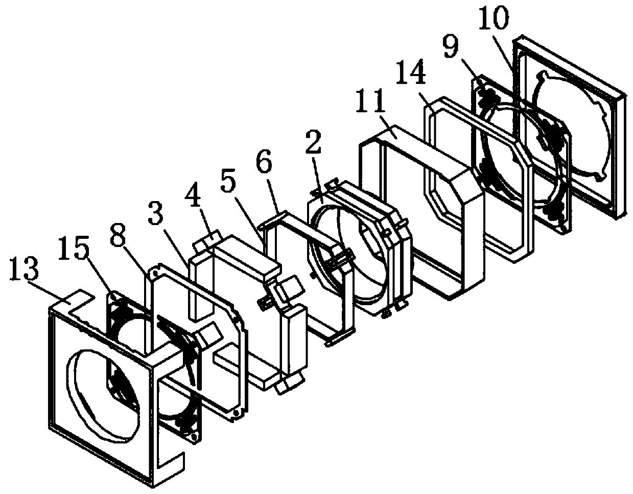
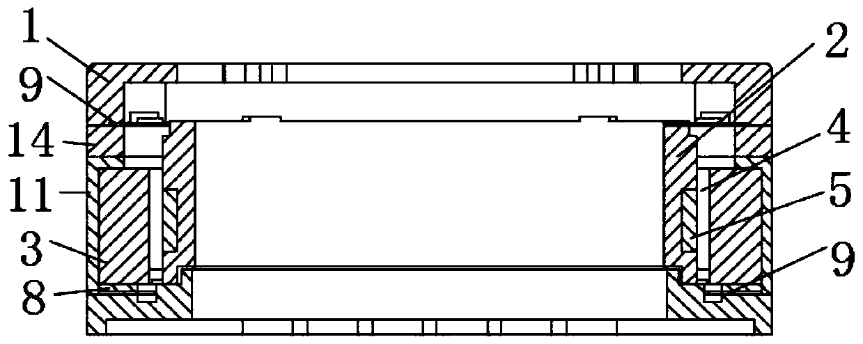
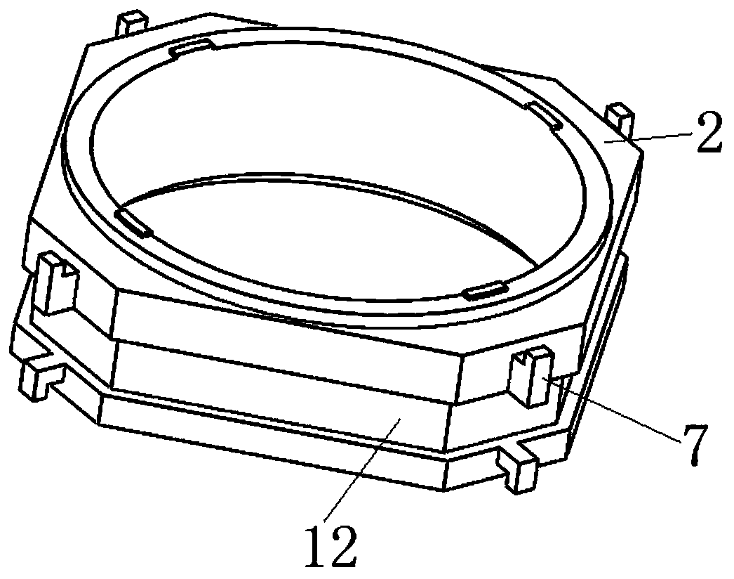
[0031] see Figure 1-6 , in the embodiment of the present invention, the anti-shake lens drive device includes a housing 1 and a carrier 2, the upper and lower parts of the carrier 2 are elastically connected in the housing 1, and further includes:

[0032] The anti-shake magnet 4, the anti-shake magnet 4 is fixedly connected in the housing 1, and the anti-shake magnet 4 is equidistantly arranged on the outside of the carrier 2;

[0033] Anti-shake coil 6, on...


PUM


Abstract

The invention discloses an anti-jittering lens driving device, and the device comprises a shell and a carrier, wherein the upper portion and the lower portion of the carrier are elastically connectedinto the shell. The device further comprises anti-jittering magnets which are fixedly connected into the shell and arranged on the outer side of the carrier at equal intervals; an anti-jitter coil, wherein one plane of the anti-jittering coil is parallel to the inner end surfaces of the anti-jittering magnets, and the other plane is fixedly connected to the outer end surface of the carrier in parallel. The position of the anti-jitter coil is corresponding to that of the anti-jitter magnets. After being electrified, the anti-jittering coil is matched with the anti-jittering magnets to generatean electromagnetic force perpendicular to the optical axis of the lens, so as to drive the carrier and the lens to move in a direction parallel to the image sensor to achieve the anti-jittering function. According to the invention, the hand jittering during image shooting can be effectively compensated, so that the surrounding imaging effect is good. Meanwhile, the structure is simple and is matched with the small size of a mobile phone or portable camera equipment.

Description

technical field [0001] The invention relates to the technical field of anti-shake lens equipment, in particular to an anti-shake lens driving device. Background technique [0002] At present, the optical anti-shake lens drive devices used in mobile phones and other micro-camera equipment at home and abroad mainly have two structures: one is translational type, and the other is shaft-shifting type; the translational type is for parallel movement relative to the image sensor, The shaft-shifting type is tilted relative to the image sensor, and both can perform corresponding translation or tilt movements according to the motion direction and displacement detected by the motion sensor, such as a gyroscope or an accelerometer, so as to stabilize the image. , for the purpose of compensating for hand shake. [0003] The shaft-shifting optical anti-shake lens drive device performs tilting movement relative to the image sensor to realize the anti-shake function, and performs vertical...

Claims


Application Information

Patent Timeline
Patent Type & Authority Applications(China)
IPC IPC(8): G03B5/02G03B13/36
CPCG03B5/02G03B13/36
Inventor 刘铁刚崔桥军吴东东
Owner 安庆市东勤电子科技有限公司
Why Eureka
Try Eureka