
Trigger type power-on and controllable power-off power supply control scheme

A power control and electrical control technology, applied in battery circuit devices, current collectors, electric vehicles, etc., can solve problems such as data loss, loss of control, and the inability of equipment to enter a low-power sleep state.

Pending Publication Date: 2021-03-19
JIANGSU GTAKE ELECTRIC CO LTD
View PDF0 Cites 0 Cited by
  • Summary
  • Abstract
  • Description
  • Claims
  • Application Information

AI Technical Summary

Problems solved by technology

[0006] b) When the device is used in a car, the control power supply sometimes needs to be connected to normal power, that is, the primary and secondary switches are always on, and the device cannot enter a low-power sleep state;
[0007] c) When the device is in operation, when the device is connected to normal power (that is, the primary switch is normally closed), and the secondary switch is disconnected urgently, the control power supply will suddenly lose power, which may cause data loss or even loss of control, serious cause safety accident

Method used


Image

  • Trigger type power-on and controllable power-off power supply control scheme
  • Trigger type power-on and controllable power-off power supply control scheme
  • Trigger type power-on and controllable power-off power supply control scheme

Examples


Embodiment Construction

[0069] The following will clearly and completely describe the technical solutions in the embodiments of the present invention with reference to the accompanying drawings in the embodiments of the present invention. Obviously, the described embodiments are only some, not all, embodiments of the present invention. Based on the embodiments of the present invention, all other embodiments obtained by persons of ordinary skill in the art without making creative efforts belong to the protection scope of the present invention.

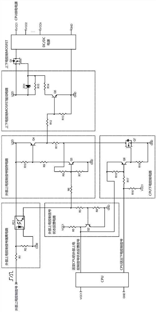
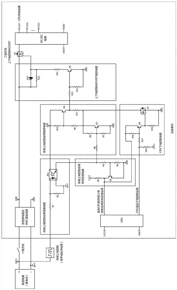
[0070] Such as Figure 2-4 It shows a power control scheme of trigger power-on and controllable power-off, including external power-on control signal isolation circuit (R1, R2, PC1), external power-on control signal state feedback circuit (R3, R4, R5, Q2), external power-on control signal latch circuit (R6, R7, R8, R9, R10, R11, Q3, Q4), CPU power-off control circuit (R16, R17, R18, R19, Q6, Q7), power on and off Control MOSFET drive circuit (R12, R13, R14, R...


PUM


Abstract

The invention discloses a trigger type power-on and controllable power-off power supply control scheme. The power supply control scheme comprises an external power-on control signal isolation circuit,an external power-on control signal latch circuit, an external power-on control signal state feedback circuit, a CPU power-off control circuit, a power-on and power-off control MOSFET drive circuit,a power-on and power-off control MOSFET (Q1), a DC / DC power supply and a CPU circuit. Due to the fact that an external power-on control signal latch circuit is arranged, latching can be conducted whena first effective high-level pulse is detected, and the anti-jitter function of a power-on signal can be achieved; and after the equipment finishes all operation functions, the CPU can automaticallycontrol power-off to enter a low-power-consumption sleep mode, and the equipment can be awakened through an external power-on control signal.

Description

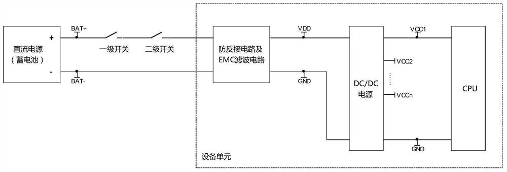
technical field [0001] The invention relates to the technical field of power supply control, in particular to a power supply control scheme for new energy vehicle motor controllers, electric motorcycle controllers, communication power supplies, household appliances and other fields that need to be powered on through external hard wires. Background technique [0002] In common products, the control power is generally directly controlled by mechanical or electrical switches, and the design is relatively simple and easy to implement, such as figure 1 , the control power supply passes through the first-level switch, then connects to the second-level switch, and finally connects to the control power supply port of the device. [0003] figure 1 The control method of the circuit is: when the first-level switch is turned on, the power is turned on through the second-level switch, so that the equipment is in a power supply state. [0004] The control power supply mode has the follo...

Claims


Application Information

Patent Timeline
IPC IPC(8): H02J1/00H02J7/00
CPCH02J1/00H02J7/0063
Inventor 候贤标刘玉虎
Owner JIANGSU GTAKE ELECTRIC CO LTD
Learn More