
Shooting method and terminal equipment

A technology for terminal equipment and shooting scenes, which is applied in the field of communication and can solve the problems of poor lighting effect of fill light and other problems.

Active Publication Date: 2019-12-06
VIVO MOBILE COMM CO LTD
View PDF5 Cites 4 Cited by
  • Summary
  • Abstract
  • Description
  • Claims
  • Application Information

AI Technical Summary

Problems solved by technology

[0004] Embodiments of the present invention provide a shooting method and terminal equipment to solve the problem of poor supplementary light effect in existing supplementary lights

Method used


Image

  • Shooting method and terminal equipment
  • Shooting method and terminal equipment
  • Shooting method and terminal equipment

Examples


Embodiment Construction

[0029] The following will clearly and completely describe the technical solutions in the embodiments of the present invention with reference to the accompanying drawings in the embodiments of the present invention. Obviously, the described embodiments are part of the embodiments of the present invention, but not all of them. Based on the embodiments of the present invention, all other embodiments obtained by persons of ordinary skill in the art without creative efforts fall within the protection scope of the present invention.

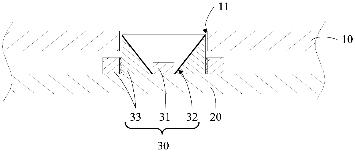
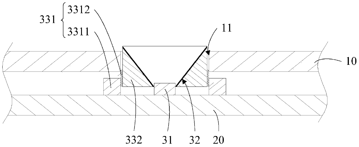
[0030] Such as Figure 1 to Figure 4 As shown, an embodiment of the present invention provides a terminal device, including:

[0031] A housing 10, the housing 10 has a through hole 11;

[0032] A circuit board 20, the circuit board 20 is located inside the housing 10;

[0033] The supplementary light module 30, the supplementary light module 30 includes a supplementary light 31, a supplementary light lamp cover 32 and a driving assembly 33, the supp...


PUM


Abstract

The invention provides a shooting method and terminal equipment, and the terminal equipment comprises: a housing which is provided with a through hole; a circuit board which is located on the inner side of the shell; a light supplement lamp module, wherein the light supplementing lamp module comprises a light supplementing lamp, a light supplementing lamp cover and a driving assembly, the light supplementing lamp and the driving assembly are both arranged on the side, facing the through hole, of the circuit board, the light supplementing lamp and the driving assembly are both electrically connected with the circuit board, the light supplementing lamp cover is connected with the driving assembly, the driving assembly can drive the light supplementing lamp cover to at least partially extendout of the shell or retract into the shell through the through hole, and the light supplementing lamp is at least partially located in a containing space formed by the light supplementing lamp cover.In this way, focusing processing can be conducted on the light supplementing lamp, and the light supplementing effect of the light supplementing lamp module is optimized.

Description

technical field [0001] The present invention relates to the field of communication technologies, in particular to a photographing method and terminal equipment. Background technique [0002] At present, terminal devices such as smartphones are equipped with powerful camera combinations, such as wide-angle / blurring cameras, etc. At the same time, in order to achieve better photo effects in dark light environments, terminal devices are equipped with fill lights. However, the supplementary lights equipped with terminal devices such as smart phones on the market are all fixed-focus supplementary lights, and the divergence angle of the supplementary light is constant, and the current of the supplementary light is also constant. However, in the face of a variety of shooting scenes, it is difficult to maximize the use of the fill light of the fixed-focus fill light. For example, for macro scenes, the divergence angle of the fill light is too large, resulting in the waste of part of...

Claims


Application Information

Patent Timeline
Patent Type & Authority Applications(China)
IPC IPC(8): H04N5/235H04N5/225
CPCH04N23/56H04N23/74
Inventor 翟敬全
Owner VIVO MOBILE COMM CO LTD
Learn More