The formwork used for forming the reverse sill at the bottom of the indoor waterproof and moisture-proof filled wall

A technology for filling walls and formwork, applied in the direction of formwork/formwork/work frame, connection parts of formwork/formwork/work frame, on-site preparation of building components, etc. problem, to achieve the effect of convenient cooperation

Active Publication Date: 2021-05-04
CHONGQING HUASHUO CONSTR
View PDF6 Cites 0 Cited by
  • Summary
  • Abstract
  • Description
  • Claims
  • Application Information

AI Technical Summary

Problems solved by technology

[0003] The purpose of the present invention is to provide a formwork for forming the reverse sill at the bottom of the indoor waterproof and moisture-proof filled wall, so as to solve the problem that the formwork in the prior art is not easy to reinforce when the wall bottom is formed at the bottom of the sill, and the formation of the reverse sill needs to consume a large amount of internal support. question

Method used


Image

  • The formwork used for forming the reverse sill at the bottom of the indoor waterproof and moisture-proof filled wall
  • The formwork used for forming the reverse sill at the bottom of the indoor waterproof and moisture-proof filled wall
  • The formwork used for forming the reverse sill at the bottom of the indoor waterproof and moisture-proof filled wall

Examples


Embodiment 1

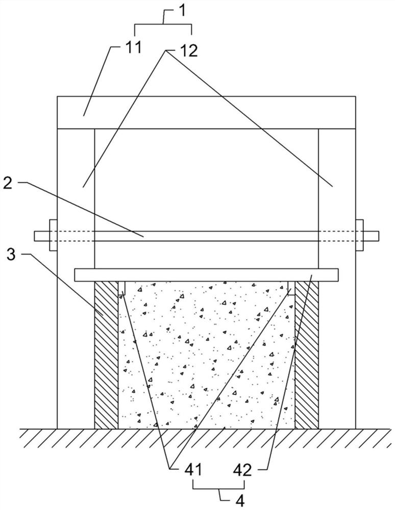
[0022] Embodiment one: as attached figure 1 Shown: the formwork used for forming the reverse sill at the bottom of the indoor waterproof and moisture-proof filling wall, including formwork groups and supporting mechanisms, the formwork group 3 includes two parallel formworks 3, and the forming for pouring the reverse sill is formed between the two formworks 3 space. The support mechanism includes an outer fixture 1 and an inner support 4, the outer fixture 1 includes two vertically arranged support rods 12 and a connecting rod 11, the connecting rod 11 is located between the two supporting rods 12 and is connected to the two supporting rods. The rods 12 are rigidly connected, and two support rods 12 and one connecting rod 11 form a door-shaped structure; a horizontal locking adjustment part is arranged between the two support rods 12, and the locking adjustment part is located below the connecting rod 11, and the locking The adjusting member is preferably a pull bolt 2 , and ...

Embodiment 2

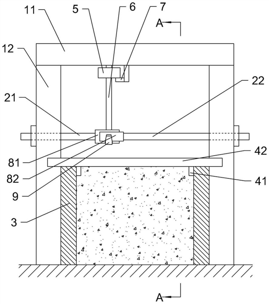
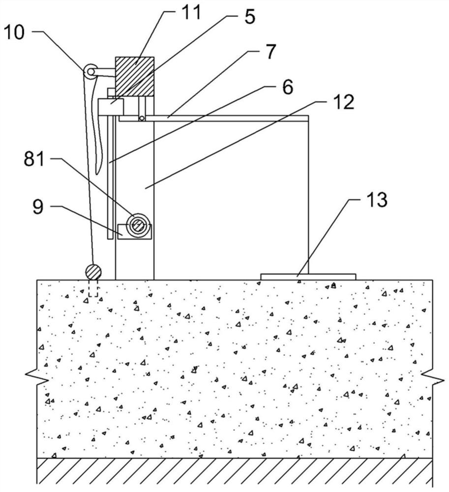
[0024] Embodiment two: the difference with embodiment one is only: as figure 2 and image 3 As shown, the pull bolt 2 includes a first screw 21 and a second screw 22, the first screw 21 and the second screw 22 are coaxially separated, and the end of the first screw 21 facing the second screw 22 is coaxially welded with a sleeve 81, the side wall of the sleeve 81 is provided with a first bayonet that runs through the side wall of the sleeve 81, and the end of the second screw 22 facing the first screw 21 is welded with a slider 82, the slider 82 is inserted into the sleeve 81 and Slidingly fit with the sleeve 81 along the axis of the sleeve 81, the slider 82 is provided with a second bayonet opposite to the first bayonet; The block 9 in the bayonet; the top of the casing 81 is provided with a vertical guide rod 6, and the upper end of the guide rod 6 is threadedly connected with the connecting rod 11; 5 is greater than the weight of the inner support 4; the connecting rod 11...


PUM


Abstract

The invention belongs to the technical field of forming equipment for concrete structures at the bottom of building walls, in particular to a formwork for forming the bottom of an indoor waterproof and moisture-proof filled wall, including a formwork group and a supporting mechanism. The formwork group includes two formworks arranged in parallel, and the support The mechanism includes an outer fixing part and an inner supporting part. The outer fixing part includes a horizontal connecting rod, and the two ends of the connecting rod are respectively fixedly connected with vertical supporting rods. The supporting rods are attached to the outside of the formwork. A horizontal locking adjustment piece is connected between the middle parts, and the inner supporting piece includes a cross bar and a stop bar vertically fixedly connected to the cross bar. The cross bar is against the top of the formwork, and the stop bar is against the inner side of the formwork. This solution solves the problems in the prior art that the formwork is not easy to be reinforced when the wall bottom is formed in reverse sill, and the problem that a large amount of internal support is consumed in the formation of the reverse sill.

Description

technical field [0001] The invention belongs to the technical field of forming equipment for concrete structures at the bottom of building walls, and in particular relates to a formwork for reverse sill forming at the bottom of indoor waterproof and moisture-proof filled walls. Background technique [0002] At present, the bottom of some waterproof and moisture-proof filling walls will be poured with concrete anti-sills to enhance the sealing between the wall and the ground. When the reverse sill is poured and formed, it is necessary to support the formwork. Since the formwork is directly supported on the flat ground, the formwork will lack a supporting position when it is reinforced, which makes the reinforcement of the formwork more troublesome. At the same time, when ensuring that the size of the concrete pouring cavity surrounded by the formwork meets the requirements, it is necessary to set up inner supports to support the formwork. After the concrete pouring is complet...

Claims


Application Information

Patent Timeline
Patent Type & Authority Patents(China)
IPC IPC(8): E04G13/00E04G17/00
CPCE04G13/00E04G17/001
Inventor 程帅王飞车军伟杨世林
Owner CHONGQING HUASHUO CONSTR
Why Eureka
Try Eureka