
combination device

A combination device and installation groove technology, applied in the direction of coupling devices, electrical components, connections, etc., can solve problems such as inability to ensure rotation, inability to ensure circuit board connection, inability to limit electrical connectors and the circuit board, etc., to achieve tight connection Effect

Active Publication Date: 2021-02-26
DEYI PRECISION ELECTRONIC IND CO LTD PANYU
View PDF5 Cites 0 Cited by
  • Summary
  • Abstract
  • Description
  • Claims
  • Application Information

AI Technical Summary

Problems solved by technology

[0004] However, after the circuit board is arranged above the buckle part, the buckle part cannot guarantee to rely on its own center of gravity to rotate around the fulcrum so as to move the buckle part toward the outside of the through hole. Swing, so that the buckle part cannot be arranged on the outside of the through hole to prevent the circuit board from moving downward, so that the electrical connector and the circuit board cannot be limited to the upper and lower sides of the buckle between, ultimately does not guarantee the connection between the electrical connector and the circuit board

Method used


Image

  • combination device
  • combination device
  • combination device

Examples


Embodiment Construction

[0050] In order to facilitate a better understanding of the purpose, structure, features, and effects of the present invention, the present invention will now be further described in conjunction with the accompanying drawings and specific embodiments.

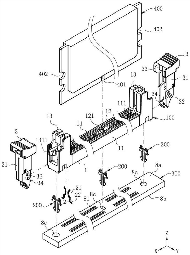
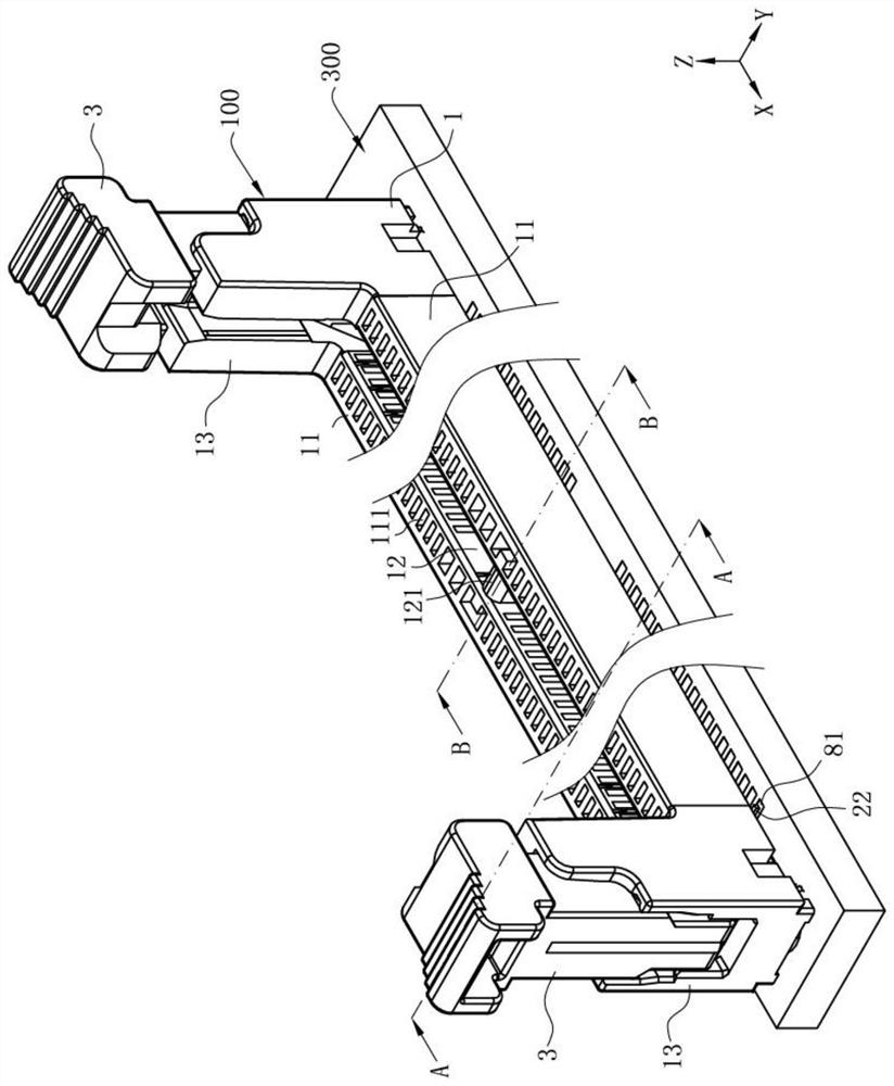
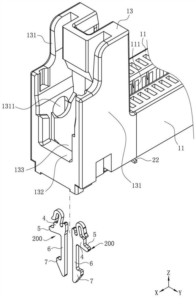
[0051] Such as figure 1 and Figure 4 As shown, the combination device of the first embodiment of the combination device of the present invention includes a first device, at least one buckle 200 and a second device, and the buckle 200 connects the first device and the second The unit snaps together. In this embodiment, the first device is an electrical connector 100, the second device is a circuit board 300, and there are multiple buckling members 200, and the electrical connector 100 is buckled. on the circuit board 300 . In other embodiments, the first device and the second device may be non-electrical components.

[0052] Such as figure 1 and figure 2 As shown, the electrical connector 100 is a DDR connector, which in...


PUM


Abstract

The invention discloses a combination device comprising: a first device is provided with a mounting groove penetrating through its bottom, and the mounting groove is provided with a limiting part; the second device has a through hole penetrating up and down; There is a gap in the up and down direction; the buckle is correspondingly accommodated in the installation groove, the buckle includes a base and a connecting foot extending downward from the base, the base is arranged in the installation groove, and the limit part is used to stop the buckle The bottom is disengaged from the installation groove, and the connecting foot is inserted downward into the through hole. The connecting foot is extended in a transverse direction to the outside of the through hole to form a buckle part. The buckle part is located on the same side of the connecting foot in the lateral direction, and the extension part is arranged in the gap. The second device abuts the extension part upwards to drive the extension part to drive the buckle part to swing out of the through hole, so as to effectively ensure that the second device is positioned at the The upper part of the locking part is used to stop the upward movement of the locking part, so as to ensure the tight connection between the first device and the second device.

Description

【Technical field】 [0001] The invention relates to a combined device, in particular to a combined device in which an electrical connector cooperates with a circuit board through a buckle. 【Background technique】 [0002] There is an existing combined device for connecting an electrical connector to a circuit board through a buckle, wherein the electrical connector is arranged above the circuit board, and the buckle includes a base and downwards from the base. An extended connecting foot, the electrical connector is provided with a mounting groove for accommodating the base, the mounting groove is provided on a bearing portion for preventing the base from moving downward, and the circuit board is provided with a A through hole into which the connecting pin is inserted, and a buckle portion is provided on the connecting pin extending toward the outside of the through hole in a transverse direction. [0003] The assembly process of the electrical connector is as follows: first, ...

Claims


Application Information

Patent Timeline
Patent Type & Authority Patents(China)
IPC IPC(8): H01R12/70
CPCH01R12/7011
Inventor 方飞龙蒋华李志杰殷佳旭
Owner DEYI PRECISION ELECTRONIC IND CO LTD PANYU
Learn More