Indoor basketball stand for junior high school students

A technology for basketball racks and junior high school students, applied in the field of basketball racks to achieve the effect of adjustable height

Inactive Publication Date: 2019-12-31
周有亮
View PDF1 Cites 0 Cited by
  • Summary
  • Abstract
  • Description
  • Claims
  • Application Information

AI Technical Summary

Problems solved by technology

[0005] Aiming at the deficiencies of the prior art, the present invention provides an indoor basketball hoop for junior high school students, which has the advantages of

Method used


Image

  • Indoor basketball stand for junior high school students
  • Indoor basketball stand for junior high school students
  • Indoor basketball stand for junior high school students

Examples


Embodiment Construction

[0026] The following will clearly and completely describe the technical solutions in the embodiments of the present invention with reference to the accompanying drawings in the embodiments of the present invention. Obviously, the described embodiments are only some, not all, embodiments of the present invention. Based on the embodiments of the present invention, all other embodiments obtained by persons of ordinary skill in the art without making creative efforts belong to the protection scope of the present invention.

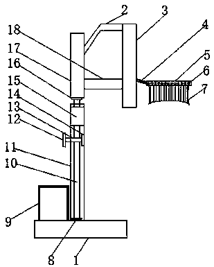
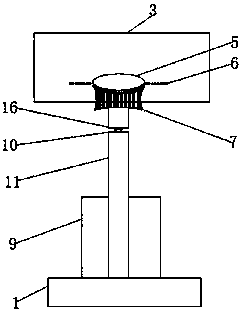
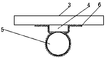
[0027] see Figure 1-5 , an indoor basketball stand for junior high school students, comprising a base 1, the top of the base 1 is provided with a placement box 9 and a lower support column 11, the bottom of the placement box 9 is welded to the top of the base 1, and the placement box 9 is located at the bottom of the lower support column 11 On the left side, the inside of the placement box 9 is welded with a partition 19, and the partition 19 divides the plac...


PUM


Abstract

The invention provides an indoor basketball stand for junior high school students, and relates to the field of basketball stands. The indoor basketball stand for the junior high school students comprises a base; the top of the base is provided with a placing box and a lower support column; an upper support column is arranged above the lower support column; the upper support column is fixedly connected to a backboard through a diagonal pull rod and a horizontal pull rod; the side of the backboard is fixedly connected to a basketball hoop through a connecting block; and a net is bonded to the bottom of the basketball hoop. According to the indoor basketball stand for the junior high school students, a second screw is driven to rotate by turning a wheel, and the second screw drives a first screw to perform lifting movement; therefore, the upper support column is driven to move up and down, and the purpose of adjusting the height of the basketball stand is achieved; and therefore, the problem that not every junior high school students can enjoy the thrill of dunk because everyone has different height is solved.

Description


Claims


Application Information

Patent Timeline
Owner 周有亮
Why Eureka
Try Eureka