A circular circulating fluidized bed boiler with a built-in tail flue and its driving power generation system

A circulating fluidized bed and tail flue technology, applied in fluidized bed combustion equipment, machines/engines, indirect carbon dioxide emission reduction, etc. Different states, etc., to avoid heat absorption and serious temperature unevenness, improve uniformity, and achieve the effect of energy

Active Publication Date: 2021-03-19
SOUTHEAST UNIV
View PDF6 Cites 0 Cited by
  • Summary
  • Abstract
  • Description
  • Claims
  • Application Information

AI Technical Summary

Problems solved by technology

Although a variety of flue expansion designs are adopted, this sequentially converging upper flue structure fundamentally leads to the dynamic state at the outlet of each cyclone separator (especially the cyclone separator located on the same side of the furnace body) Different, which will cause uneven loading of the cyclone separator
Especially in the case of variable operating conditions, this unevenness will be more serious; (2) The increased heating surface will lead to the inhomogeneous distribution of the heat load in the coal-fired boiler along the width and depth of the furnace.

Method used


Image

  • A circular circulating fluidized bed boiler with a built-in tail flue and its driving power generation system
  • A circular circulating fluidized bed boiler with a built-in tail flue and its driving power generation system
  • A circular circulating fluidized bed boiler with a built-in tail flue and its driving power generation system

Examples


Embodiment Construction

[0043] The technical solution of the present invention will be further described below in conjunction with the accompanying drawings.

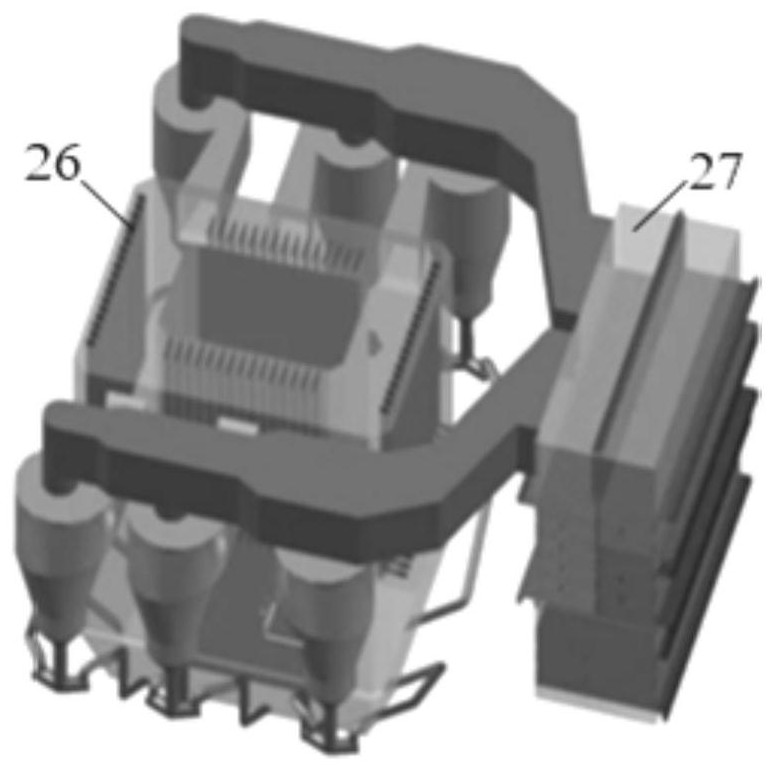
[0044] As shown in Figure 1(a), the inventors have found through research that the tail flue 27 of the circulating fluidized bed boiler in the prior art is arranged on the side of the boiler body 26, which is one of the reasons for the asymmetry of the structure of the separator outlet flue. one. At present, almost all circulating fluidized beds use the tail flue located on one side of the furnace body, and the flue gas from the outlets of multiple separators is sequentially collected into one or two upper flues, and then leads to the tail flue. The fluidized bed boiler system of this design occupies a large area as a whole. At the same time, this sequentially converging flue structure fundamentally determines the difference in the dynamic state at the outlet of each separator, resulting in uneven working conditions of the separators. . The ...


PUM


Abstract

The invention discloses a tail flue built-in loop-shaped circulating fluidized bed boiler and a driving power generation system thereof. The boiler comprises a loop-shaped hearth, a tail flue arrangedin a boiler loop-shaped inner cavity and separators symmetrically arranged with respect to the center of the hearth, wherein cold walls are uniformly distributed on an inner ring and an outer ring ofthe loop-shaped hearth, and are divided into a first region cold wall and a second region cold wall according to functional characteristics, and a flue gas mixing chamber, a low-temperature reheater,a primary air preheater, a flue gas cooler and a secondary air preheater are sequentially arranged in the tail flue in the flue gas flow direction. The boiler has the beneficial effects that the structure of the existing boiler is compact and integrated, the boiler island occupied space is reduced about one third, meanwhile, the separators which are symmetrically arranged in the center and the flue gas mixing chamber enable flue gas to be symmetrically collected, so that the uniformity of the load of the separators are effectively increased, according to the gas-solid flow state and the heatdistribution in the hearth, the side wall area and the four-corner area in the hearth the width and the deep direction are divided into heating areas with different functions, energy loss is reduced,and flexible adjustment is realized.

Description

technical field [0001] The invention relates to a circulating fluidized bed boiler and its drive power generation system, in particular to a circular circulating fluidized bed boiler with a built-in tail flue and its drive power generation system. Background technique [0002] During the enlargement process of the circulating fluidized bed coal-fired boiler, the proportion of the heating surface in the high temperature area increases due to the increase rate of the heating area of ​​the boiler furnace is lower than the increase rate of the heat release capacity of the furnace, and the arrangement of the heating surface is difficult. Universal challenge. Simply increasing the heating surface in the furnace may make the heating screens in the furnace too densely arranged, resulting in serious uneven combustion dynamic field and heat transfer in the furnace, which will bring about boiler efficiency and safety problems; while simply increasing the furnace volume capacity will T...

Claims


Application Information

Patent Timeline
Patent Type & Authority Patents(China)
IPC IPC(8): F23C10/02F23C10/20F23C10/26F23C10/28F23L15/04F01D15/10
CPCF01D15/10F23C10/02F23C10/20F23C10/26F23C10/28F23L15/04Y02E20/34
Inventor 钟文琪刘雪娇邵应娟崔颖
Owner SOUTHEAST UNIV
Why Eureka
Try Eureka