Anti-fog camera

A camera and anti-fog technology, applied in image communication, television, optics, etc., can solve the problems of long time, inconvenient to clean water mist, and reduce the clarity of camera monitoring, so as to increase the defogging area and improve the defogging. The effect of efficiency

Active Publication Date: 2020-01-10
SHENZHEN FSAN INTELLIGENT TECH
View PDF9 Cites 12 Cited by
  • Summary
  • Abstract
  • Description
  • Claims
  • Application Information

AI Technical Summary

Problems solved by technology

[0003] When the outside air temperature is low and the humidity is high (for example, in the early morning or evening in autumn and winter), the high-concentration and low-temperature water vapor in the air contacts the outer surface of the lens of the camera, and the internal electronic components of the camera heat up when the camera is working. Therefore, the temperature is high, and the low-temperature water vapor will liquefy on the outer surface of the high-temperature lens and form a layer of water mist, which greatly reduces the clarity of camera monitoring. Since the cameras used for monitoring are generally installed at high places, this makes It is very inconvenient to clean up the water mist, and in some key monitoring places (such as banks), a large number of cameras will be installed, and it will take a long time to clean up the water mist

Method used


Image

  • Anti-fog camera
  • Anti-fog camera
  • Anti-fog camera

Examples


Embodiment 1

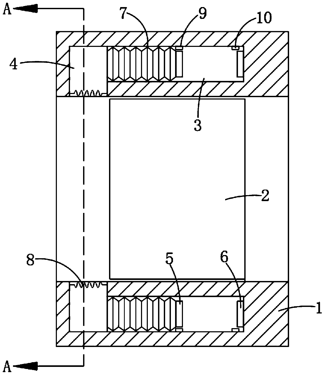
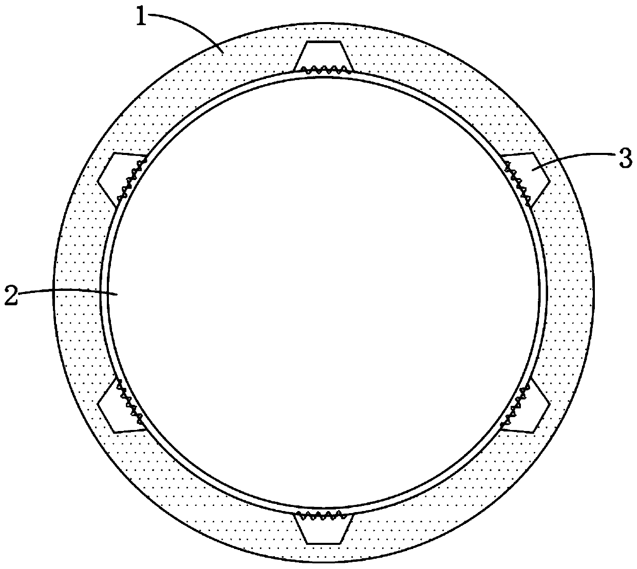
[0021] refer to Figure 1-2 , an anti-fog camera, comprising a lens barrel 1, a lens 2 is embedded in the lens barrel 1, a plurality of strip grooves 3 are provided on the side wall of the lens barrel 1 at equal intervals along its circumference, and a plurality of strip grooves 3 are provided on the side wall of the lens barrel 1 There are a plurality of wedge-shaped air outlets 4 communicating with the bar-shaped groove 3. The wedge-shaped air outlets 4 can make the discharged air cover the lens 2. The lens barrel 1 is embedded with a power generation assembly composed of a plurality of thermoelectric power generation sheets connected in series. Each The wedge-shaped air outlets 4 are embedded with heating wires 8 electrically connected to the power generation components, and the inner wall of the strip groove 3 is fixedly connected with a telescopic airbag 7, and a driving device for driving the telescopic airbag 7 to expand and contract is installed in the strip groove 3. ...

Embodiment 2

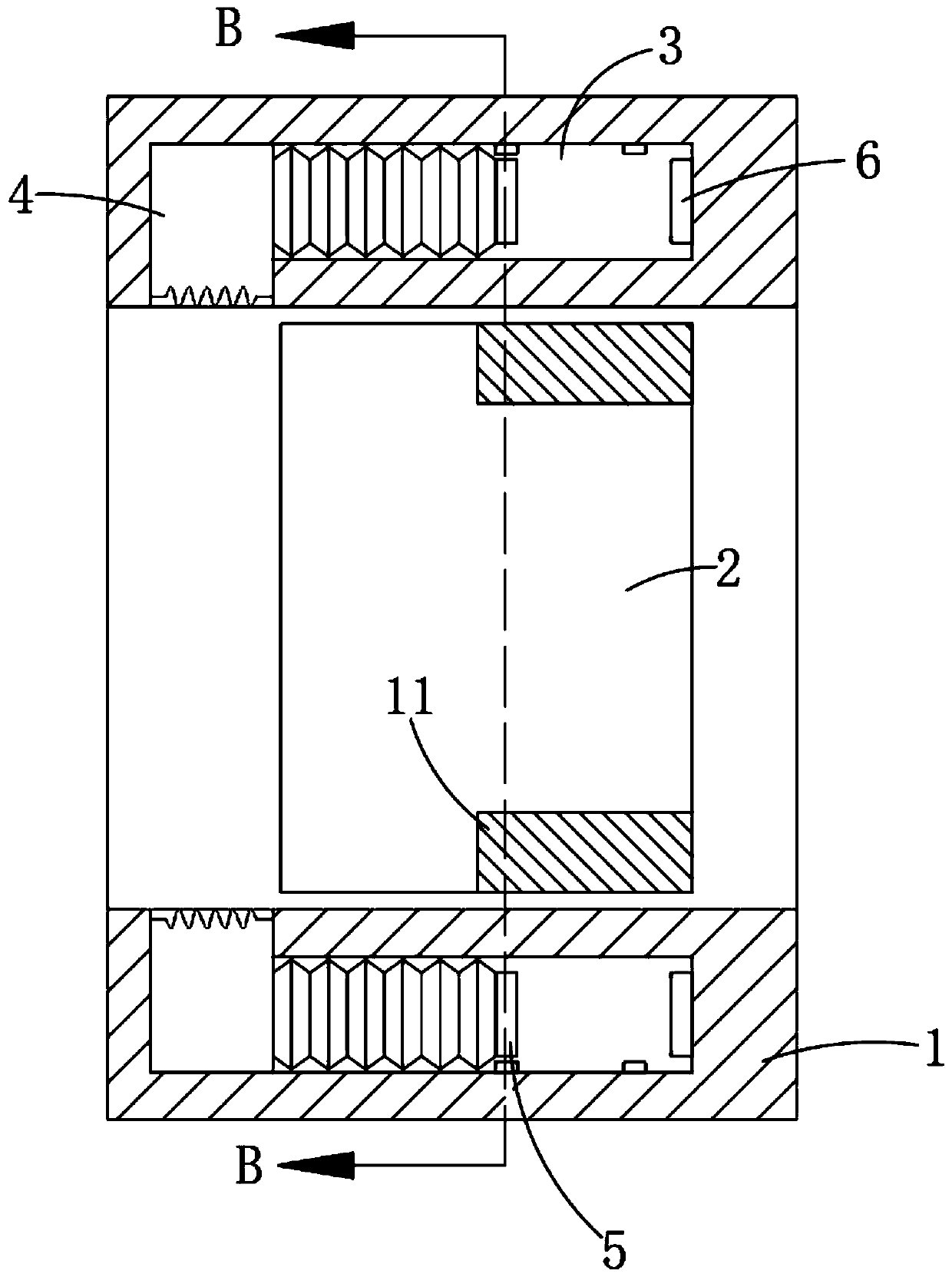
[0025] refer to Figure 3-4 , different from Embodiment 1, the lens 2 is sealed and slid with the inner wall of the lens barrel 1 to ensure that the lens 2 can rotate along its central axis without hindrance, and the circumferential side wall of the lens 2 is embedded with an arc corresponding to the electromagnet 5 Magnetic block 11, and the arc-shaped magnetic block 11 and the electromagnet 5 magnetic poles repel each other.

[0026] In this embodiment, when the electromagnet 5 is energized, it will generate a repulsive force on the arc-shaped magnetic block 11, so that the lens 2 rotates counterclockwise at a certain angle. When the electromagnet 5 is powered off, the iron core in the electromagnet 5 can attract the arc-shaped The magnetic block 11 drives the lens 2 to rotate clockwise for a certain angle. When the electromagnet 5 is energized again, the lens 2 will rotate counterclockwise for a certain angle. The hot air can cover the surface of the lens 2 more comprehens...


PUM


Abstract

The invention discloses an anti-fog camera which comprises a lens barrel, a lens is embedded in the lens barrel; a plurality of strip-shaped grooves are formed in the side wall of the lens barrel at equal intervals in the circumferential direction of the lens barrel; a plurality of wedge-shaped air outlets communicated with the strip-shaped groove are formed in the side wall of the lens barrel; apower generation assembly formed by connecting a plurality of thermoelectric power generation pieces in series is embedded in the lens barrel, an electric heating wire electrically connected with thepower generation assembly is embedded in each wedge-shaped air outlet, a telescopic air bag is fixedly connected to the inner wall of the strip-shaped groove, and a driving device for driving the telescopic air bag to stretch out and draw back is installed in the strip-shaped groove. The electromagnet drives the telescopic air bag to stretch back and forth to blow out high-speed air to the lens, the blown-out air can rapidly evaporate water mist on the lens after being heated by the electric heating wire, and the situation that monitoring definition is affected due to the fact that water mistis condensed on the lens of the camera for a long time is avoided.

Description

technical field [0001] The invention relates to the technical field of placing monitoring equipment, in particular to an anti-fog camera. Background technique [0002] Surveillance camera is a semiconductor imaging device, which has the advantages of high sensitivity, anti-glare, small distortion, small size, long life, and anti-vibration. Surveillance camera security system. [0003] When the outside air temperature is low and the humidity is high (for example, in the early morning or evening in autumn and winter), the high-concentration and low-temperature water vapor in the air contacts the outer surface of the lens of the camera, and the internal electronic components of the camera heat up when the camera is working. Therefore, the temperature is high, and the low-temperature water vapor will liquefy on the outer surface of the high-temperature lens and form a layer of water mist, which greatly reduces the clarity of camera monitoring. Since the cameras used for monitor...

Claims


Application Information

Patent Timeline
Patent Type & Authority Applications(China)
IPC IPC(8): H04N5/225G03B17/55
CPCG03B17/55H04N23/50H04N23/55
Inventor 燕燕
Owner SHENZHEN FSAN INTELLIGENT TECH
Why Eureka
Try Eureka