Flattening roller, conveying mechanism and treatment device
A technology of processing device and conveying mechanism, applied in the direction of electrolysis process and electrolysis components, can solve problems such as affecting the electroplating process and electroplating quality, and easy to form wrinkles on the surface of the plate, so as to improve the winding quality and avoid wrinkles.
- Summary
- Abstract
- Description
- Claims
- Application Information
AI Technical Summary
Problems solved by technology
Method used
Image
Examples
Embodiment 1
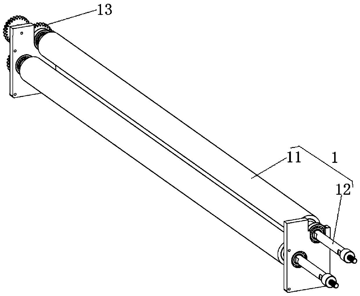
[0079] This embodiment provides a flattening roller, such as image 3 As shown, the flattening roller 1 includes a roller base body 11 and a rotating shaft 12. The rotating shaft 12 is coaxially arranged with the roller base body 11 and passes through both ends of the roller base body 11. Along the circumferential direction of the flattening roller 1, In at least part of the flattening roller 1, the radial distance of the rotation axis 121 of the flattening roller 1 toward the outer surface thereof is gradually reduced along the extending direction of the rotation axis 121 from the middle section of the flattening roller 1 toward its two ends, and the flattening roller 1 is set. The outer peripheral surface of the flat roll 1 is a curved surface. That is, the maximum perimeter of the middle section of the flattening roller 1 in the circular motion around the axis of rotation 121 is greater than the maximum perimeter of the two ends of the flattening roller 1 in the circular mo...
Embodiment 2
[0083] This embodiment provides a conveying mechanism, including a drive assembly and at least one flattening roller 1 in Embodiment 1. The drive assembly is used to drive the sheet to slide from the first end to the second end of the base frame 10 , and the drive assembly includes a drive shaft 21 and passive axis 31, such as figure 1 As shown, the driven shaft 31 is rotatably arranged at the first end, the driving shaft 21 is rotatably arranged at the second end, the driven shaft 31 is used for wrapping the coiled sheet, and the driving shaft 21 is used for the coiled sheet to be pulled from the driven shaft 31. The draw-out end is wound, that is, the passive shaft 31 is unwound, and the active shaft 21 is reeled. The flattening roller 1 is rotatably arranged on the sliding path of the plate between the first end and the second end, and the rotation axis 121 of the flattening roller 1 is arranged perpendicular to the sliding direction of the plate. In this embodiment, the fl...
Embodiment 3
[0086] This embodiment provides a processing device, which includes at least one processing tank and the conveying mechanism in Embodiment 2. The processing tank is arranged on the sliding path of the plate, and the wall of the processing tank located on the sliding path of the plate is provided with a plate clearance 101. The driving shaft 21 and the passive shaft 31 in the driving assembly in the conveying mechanism are respectively rotatably arranged at both ends of the processing tank along the sliding path of the sheet, and the flattening roller 1 in the conveying mechanism is rotatably arranged on the groove wall of the processing tank through the rotating shaft 12 At least one group of driving rollers 4 is arranged in any treatment tank, the driving rollers 4 are arranged in parallel with the flattening roller 1 in the axial direction, and the two ends of the driving rollers 4 are rotated and arranged on the side wall of the treatment tank. Any group of driving rollers 4 ...
PUM
 Abstract
Description
Claims
Application Information
 - R&D
- Intellectual Property
- Life Sciences
- Materials
- Tech Scout
- Unparalleled Data Quality
- Higher Quality Content
- 60% Fewer Hallucinations
Browse by: Latest US Patents, China's latest patents, Technical Efficacy Thesaurus, Application Domain, Technology Topic, Popular Technical Reports.
© 2025 PatSnap. All rights reserved.Legal|Privacy policy|Modern Slavery Act Transparency Statement|Sitemap|About US| Contact US: help@patsnap.com


