[0022] In order to make the objectives, technical solutions and advantages of the present invention clearer, the technical solutions of the present invention will be described clearly and completely in conjunction with specific embodiments of the present invention and the corresponding drawings. Obviously, the described embodiments are only a part of the embodiments of the present invention, rather than all the embodiments. Based on the embodiments of the present invention, all other embodiments obtained by those of ordinary skill in the art without creative work shall fall within the protection scope of the present invention.
[0023] The technical solutions disclosed in the various embodiments of the present invention will be described in detail below with reference to the accompanying drawings.
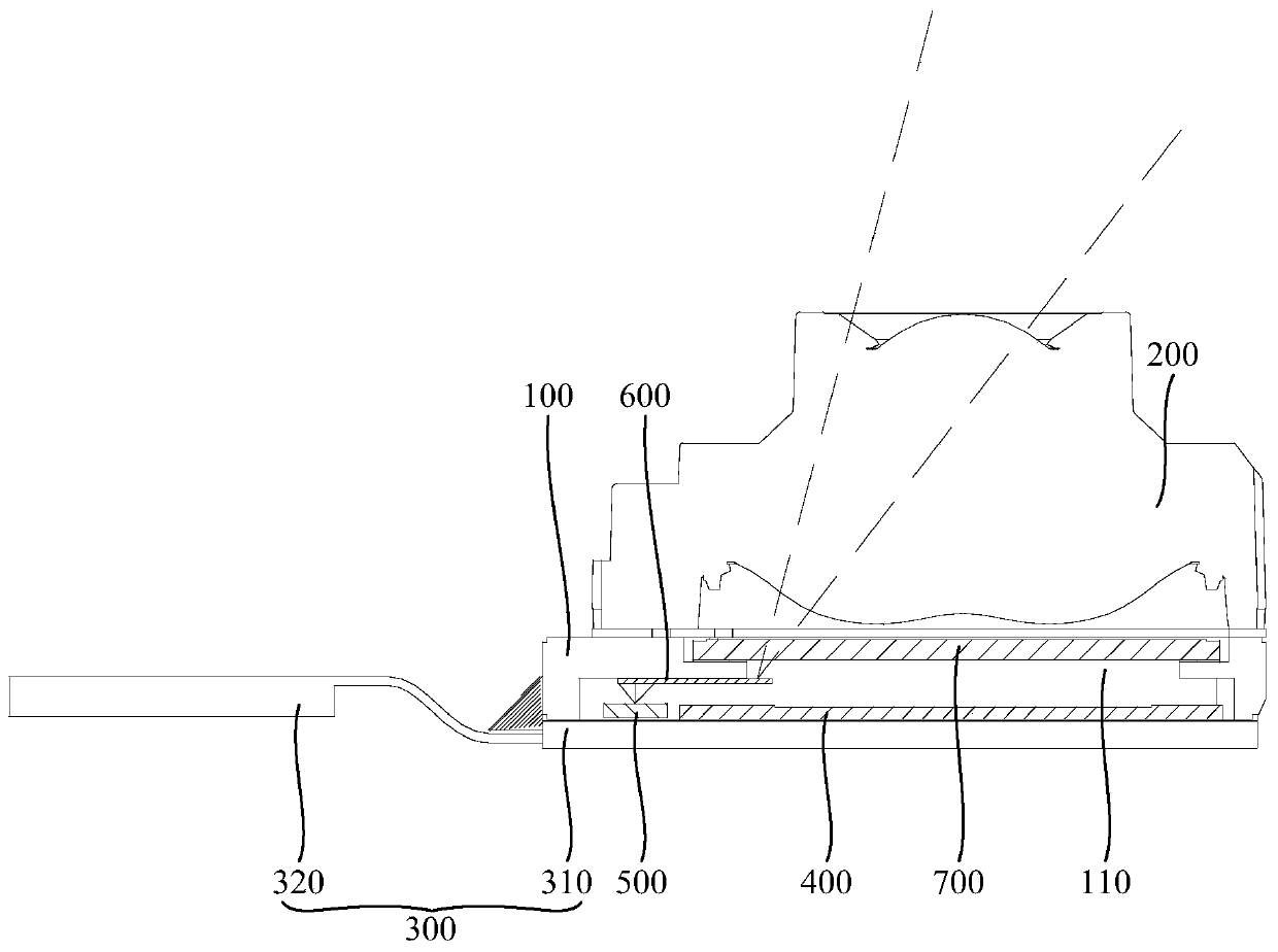
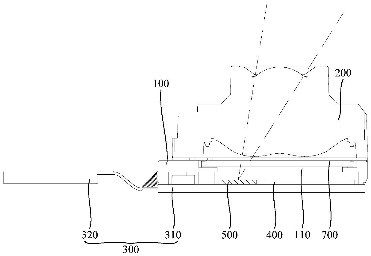
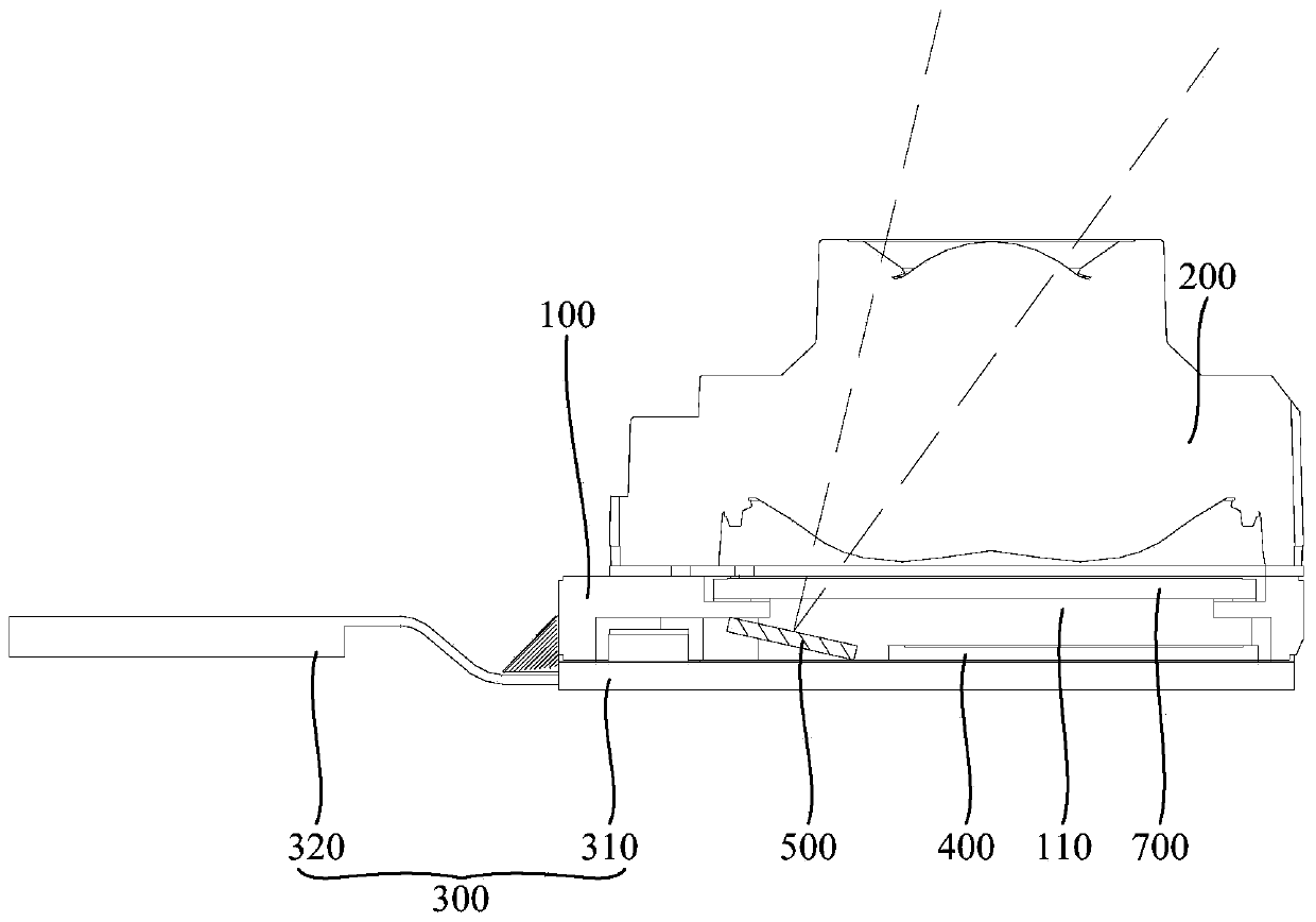
[0024] Such as figure 1 As shown, the embodiment of the present invention discloses a camera module. The camera module may be applied to electronic equipment, and specifically may include a bracket 100, a lens group 200, a circuit board 300, an image sensor 400, and a light emitting device 500.
[0025] The bracket 100 can be used as an installation basis for the components included in the camera module. The lens group 200 is arranged on the holder 100. The lens group 200 may specifically include a plurality of lenses, which may be convex lenses, concave lenses, etc., and these lenses are superimposed and assembled on the holder 100 so that light can pass through the lens group 200. To the image sensor 400. The circuit board 300 is connected to the support 100, the image sensor 400 is arranged on the circuit board 300, and the image sensor 400 is electrically connected to the circuit board 300. The image sensor 400 can sense the light incident through the lens set 200, thereby converting the corresponding optical image signal It is converted into an electrical signal, and the electrical signal can be processed to obtain a corresponding image, thereby realizing the shooting function of the camera module.
[0026] The light emitting device 500 is arranged on the circuit board 300, and the light emitting device 500 can be electrically connected to the circuit board 300, so the circuit board 300 can supply power to the light emitting device 500, and can control the state of the light emitting device 500 so that the light emitting device 500 can emit light . A light guide channel is formed between the light emitting device 500 and the lens group 200, that is, the light emitted by the light emitting device 500 can propagate to the lens group 200 through the light guide channel, so as to be further emitted through the lens group 200. Optionally, the light-emitting device 500 here may specifically include at least one of a breathing light, a fill light, and an effect light. Of course, the light-emitting device 500 may also include other devices with a light-emitting function. This embodiment of the present invention does not Do restrictions.
[0027] Further, the camera module disclosed in the embodiment of the present invention may further include a filter 700, the filter 700 has a filter function, the filter 700 is arranged on the bracket 100, and the bracket 100 is provided with a light-passing hole 110, The filter 700 covers the light-passing hole 110, specifically, the filter 700 is located between the lens group 200 and the light-passing hole 110. The light passing through the lens group 200 first enters the filter 700, then passes through the light-passing hole 110, and irradiates the image sensor 400.
[0028] In the above-mentioned camera module disclosed in the embodiment of the present invention, the light emitted by the light-emitting device 500 can be emitted through the lens group 200. The light-emitting device 500 is integrated in the camera module, so the light-emitting device 500 does not additionally occupy the display of the electronic device. Area, so that the screen-to-body ratio of electronic devices increases accordingly. In addition, when using this solution, the function of the camera module is not limited to shooting, it also has a light-emitting function, so the function of the camera module is more diversified, so as to better meet the needs of users.
[0029] Considering that the light emitted by the light emitting device 500 may interfere with the shooting function of the camera module, in order to minimize the adverse effect of the light emitting device 500 on the normal shooting of the camera module, in an optional embodiment, The camera module has a first state and a second state. Wherein: in the first state, the image sensor 400 is in a photosensitive state, and the light emitting device 500 is in a non-working state. At this time, the light emitting device 500 does not emit light, and the image sensor 400 can normally sense light entering the camera module from the external environment; In the second state, the image sensor 400 is in a non-photosensitive state and the light-emitting device 500 is in an operating state. At this time, the light-emitting device 500 can emit light, but the image sensor 400 is not working. It should be noted that when the image sensor 400 is in a non-photosensitive state, the image sensor 400 no longer realizes photoelectric signal conversion. At this time, the electrical connection loop between the image sensor 400 and the circuit board 300 can be cut off, so that the image sensor 400 It cannot be light-sensitive; or, an additional light-shielding structure can be added. In this state, the light-shielding structure can be moved above the image sensor 400, thereby blocking light from reaching the image sensor 400, making the image sensor 400 unable to light-sensitize. Of course, other methods can also be used to make the image sensor 400 in a non-photosensitive state, which is not limited herein.
[0030] After adopting the above technical solution, the image sensor 400 and the light-emitting device 500 can work independently, thereby preventing the problem of interference between the image sensor 400 and the light-emitting device 500 when they work at the same time. Therefore, the solution can improve the working quality of the image sensor 400, and the image sensor 400 may not work when the light emitting device 500 emits light, thereby reducing the power consumption of the camera module and prolonging the service life of the image sensor 400.
[0031] In an alternative embodiment, the circuit board 300 may specifically include a first sub-circuit board 310 and a second sub-circuit board 320. The first sub-circuit board 310 is connected to the support 100 and the second sub-circuit board 320, respectively, and the second The sub-circuit board 320 extends relative to the bracket 100 so that the second sub-circuit board 320 is connected to other devices (such as the main board of an electronic device). At this time, the image sensor 400 and the light-emitting device 500 may be disposed on the first sub-circuit board 310 by a surface mount technology (SMT) or the like, and there may be a certain interval between the image sensor 400 and the light-emitting device 500. This prevents direct contact between the two and damage to the structure of the two. In addition, the planes where the image sensor 400 and the light emitting device 500 are located may be parallel or overlapped. Specifically, the light emitting device 500 can be arranged at any position on the first sub-circuit board 310, but considering that the position and size of the image sensor 400 will directly affect the shooting effect of the camera module, the light emitting device 500 can be arranged on the first sub-circuit board 310. At the edge of the sub-circuit board 310. That is, the light emitting device 500 is as far away from the central area of the first sub-circuit board 310 as possible, so that the first sub-circuit board 310 has a larger space for the image sensor 400 to improve the shooting effect of the camera module.
[0032] As described above, the support 100 may be provided with a light-passing hole 110, and the light incident surface of the filter 700 is opposite to the light-passing hole 110. In an alternative embodiment, such as figure 1 As shown, the camera module further includes a light guide 600, the light guide 600 is disposed on the support 100, the light incident surface of the light guide 600 is opposite to the light emitting device 500, and the light guide 600 is located in the light guide channel described above Inside, and the light-emitting surface of the light guide 600 at least partially faces the light-passing hole 110. The light guide 600 here can realize light guide, so the light emitted by the light emitting device 500 can first enter the light guide 600, and the propagation direction of these lights changes in the light guide 600, so that it can enter through the light guide 600 The light-passing hole 110 further passes through the filter 700 through the light-passing hole 110, and finally exits through the lens assembly 200. It can be seen that when the light guide 600 is installed, the light emitted by the light emitting device 500 can be reliably emitted through the light guide 600, so the installation position of the light emitting device 500 is more flexible.
[0033] Optionally, a part of the light guide 600 is disposed on the support 100, and another part of the light guide 600 is opposite to the light through hole 110, or another part of the light guide 600 extends into the light through hole 110. At this time, a part of the light guide 600 is located under the bracket 100, and the connection area between the two is larger, so that the structural strength of the light guide 600 is higher, and its position accuracy relative to the light emitting device 500 is higher, and thus more accurate The light guiding is realized so that the light emitted by the light emitting device 500 can be emitted more, so as to achieve the purpose of improving the light emitting effect of the light emitting device 500. The part of the light guide 600 opposite to the light hole 110 or the part of the light guide 600 extending into the light hole 110 can realize the emission of light, thereby reliably ensuring that the light emitted by the light emitting device 500 can be emitted through the light guide 600 . In addition, after this arrangement, the light guide 600 can be farther away from the center line of the light hole 110. When the light in the external environment enters the camera module, the light guide 600 is less likely to block the propagation of the light, thereby enhancing the camera The shooting effect of the module.
[0034] The specific structure of the light guide 600 can be flexibly selected. In order to reduce the space occupied by the light guide 600, the light guide 600 can be set as a light guide film, so that the camera module has more space for the image sensor. 400, light-emitting device 500 and other parts.
[0035] As mentioned above, the support 100 may be provided with a light-passing hole 110, and the filter 700 can cover the light-passing hole 110. Based on this, in another alternative embodiment, such as figure 2 As shown, the light emitting surface of the light emitting device 500 is at least partially opposite to the light through hole 110. In other words, at least part of the light emitted by the light-emitting device 500 can directly enter the light-passing hole 110, so as to enter the lens group 200 through the light-passing hole 110. At this time, even if the light guide structure (such as the light guide 600 described in the above embodiment) is not provided, the light emitted by the light emitting device 500 can be smoothly emitted out of the camera module. This structure can reduce the content of the camera module on the one hand. The number of parts simplifies the structure of the camera module and facilitates the layout of other parts; on the other hand, when the light in the external environment enters the camera module, it will not be blocked by the light guide structure, so the camera module The shooting effect is better.
[0036] Such as image 3 As shown, optionally, the light-emitting device 500 may be disposed on the circuit board 300 obliquely, and the light-emitting surface of the light-emitting device 500 faces the light-incident surface of the lens assembly 200. By arranging the light emitting device 500 obliquely, the light emitting direction of the light emitting device 500 can be adjusted appropriately, so that the light emitted by the light emitting device 500 is less likely to be blocked by the bracket 100, and thus it is easier to enter the lens group 200. Therefore, this structure does not need to be installed. The guide structure described above, on the other hand, can appropriately increase the distance between the light emitting device 500 and the center line of the through hole 110, so that the size of the image sensor 400 can be further increased, thereby optimizing the shooting effect of the camera module .
[0037] The tilt angle of the light-emitting device 500 can be selected flexibly. In order to make the light emitted by the light-emitting device 500 more easily enter the lens group 200, the light-emitting device 500 can be made to interfere with the circuit board 300 and the bracket 100 respectively. In other words, the light emitting device 500 can occupy the entire space between the circuit board 300 and the bracket 100. At this time, the tilt angle of the light emitting device 500 is basically at the maximum state, and more light emitted by the light emitting device 500 can enter the lens group 200. The luminous effect of 500 can be further improved. It can be seen that this structure can make full use of the space between the circuit board 300 and the bracket 100, which can ensure that the light emitted by the light emitting device 500 enters the lens group 200 more reliably, and can further increase the center of the light emitting device 500 and the light-passing hole 110 The distance between the lines, so as to achieve the purpose of improving the shooting effect of the camera module.
[0038] An embodiment of the present invention also discloses an electronic device, which includes the camera module described in any of the foregoing embodiments.
[0039] The electronic device disclosed in the embodiment of the present invention may be a smart phone, a tablet computer, an e-book reader or a wearable device. Of course, the electronic device may also be other devices, which is not limited in the embodiment of the present invention.
[0040] The above embodiments of the present invention focus on the differences between the various embodiments. As long as the different optimization features between the various embodiments are not contradictory, they can be combined to form a better embodiment. Considering the conciseness of the text, here is No longer.
[0041] The foregoing descriptions are merely embodiments of the present invention, and are not intended to limit the present invention. For those skilled in the art, the present invention can have various modifications and changes. Any modification, equivalent replacement, improvement, etc. made within the spirit and principle of the present invention should be included in the scope of the claims of the present invention.