Image annotation method and device

An image labeling and target image technology, applied in the computer field, can solve problems such as cumbersome operation and low efficiency, and achieve the effect of simplifying labeling operations and improving labeling efficiency

Inactive Publication Date: 2020-02-04
北京云聚智慧科技有限公司
View PDF3 Cites 0 Cited by
  • Summary
  • Abstract
  • Description
  • Claims
  • Application Information

AI Technical Summary

Problems solved by technology

[0004] Embodiments of the present application provide an image tagging method and device to solve the problems of cumberso

Method used


Image

  • Image annotation method and device
  • Image annotation method and device
  • Image annotation method and device

Examples


Example Embodiment

[0025] In order to make the objectives, technical solutions, and advantages of the present application clearer, the technical solutions of the present application will be described clearly and completely in conjunction with specific embodiments of the present application and the corresponding drawings. Obviously, the described embodiments are only a part of the embodiments of the present application, rather than all the embodiments. Based on the embodiments in this application, all other embodiments obtained by those of ordinary skill in the art without creative work fall within the protection scope of this application.

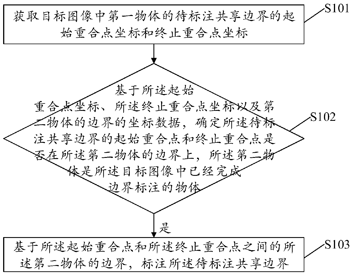
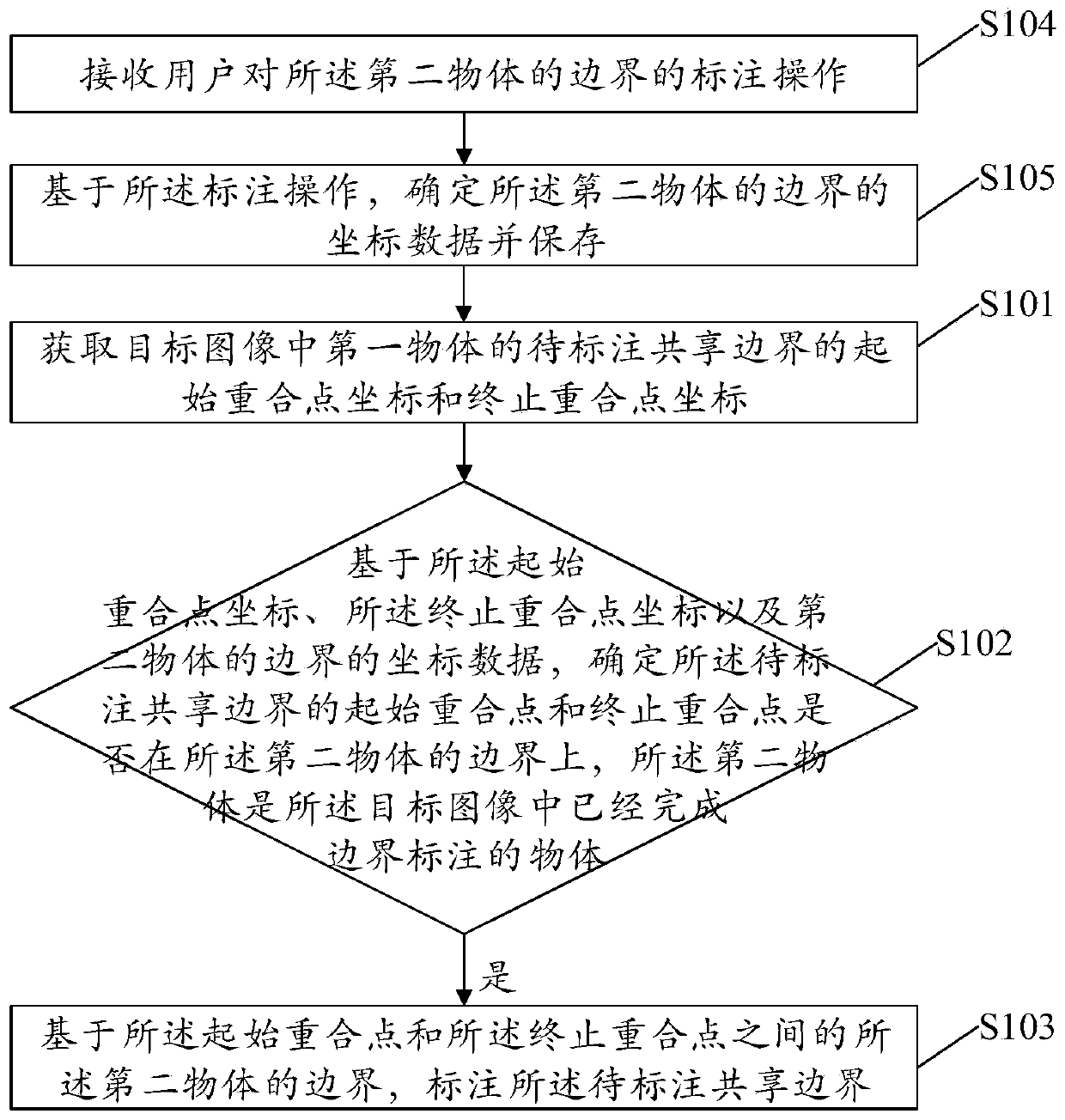
[0026] In order to solve the problem of cumbersome operation and low efficiency when the existing image labeling method labels the shared boundary of adjacent objects, the embodiments of the present application provide an image labeling method and device. The execution subject of the method may include but is not limited to A personal computer (Personal Computer...


PUM


Abstract

The invention discloses an image annotation method and device. The method comprises the steps of obtaining an initial overlap point coordinate and an end overlap point coordinate of a to-be-annotatedshared boundary of a first object in a target image; based on the starting overlap point coordinates, the ending overlap point coordinates and the coordinate data of the boundary of a second object, determining whether the starting overlap point and the ending overlap point of the to-be-labeled shared boundary are located on the boundary of the second object or not, wherein the second object is anobject with boundary labeling completed in the target image; and if so, marking the to-be-marked shared boundary based on the boundary of the second object between the starting coincidence point andthe ending coincidence point. According to the method and the device, the labeling operation of the shared boundary between the adjacent objects can be simplified, and the image labeling efficiency isimproved.

Description

technical field [0001] The present application relates to the field of computer technology, in particular to an image tagging method and device. Background technique [0002] Image semantic segmentation (semantic segmentation) refers to the method of segmenting an image according to the semantics of the image (usually, different objects in the image have different semantics). [0003] At present, the boundaries of the objects in the image are drawn by humans using the method of polygon annotation with their own vision, and then different colors are filled in different polygons to achieve the purpose of image segmentation. When different objects in the image are adjacent to each other, such as roads, vehicles and pedestrians, buildings, trees and the sky, the shared boundaries between adjacent objects will be drawn repeatedly, and the boundaries drawn each time need to be guaranteed can overlap well. However, due to the inevitable visual errors and mistakes in manual drawin...

Claims


Application Information

Patent Timeline
IPC IPC(8): G06T7/12G06T7/13
CPCG06T7/12G06T7/13
Inventor 肖苗苗
Owner 北京云聚智慧科技有限公司
Why Eureka
Try Eureka