A bidirectionally recognizable microfluidic inertial power switch

An electrical switch, microfluidic technology, applied in electrical switches, circuits, electrical components, etc., can solve problems such as long-term storage of unfavorable switches, inability to maintain reliable latching, inability to distinguish environmental forces, etc., to achieve reliable latching, simple structure, reducing fluid The effect of drop separation

Active Publication Date: 2021-09-03
NANJING UNIV OF SCI & TECH
View PDF0 Cites 0 Cited by
  • Summary
  • Abstract
  • Description
  • Claims
  • Application Information

AI Technical Summary

Problems solved by technology

However, the switch also has disadvantages, such as the large width of the microchannel, resulting in a low switching threshold of about 22g; the structure of the microchannel is simple, and the switch can only be turned on under the action of inertial force, and it cannot be reliably locked after the inertial force disappears, and cannot be distinguished Environmental force; the substrate adopts PDMS porous material, which is not conducive to the long-term storage of the switch

Method used


Image

  • A bidirectionally recognizable microfluidic inertial power switch
  • A bidirectionally recognizable microfluidic inertial power switch
  • A bidirectionally recognizable microfluidic inertial power switch

Examples


Embodiment Construction

[0037] The present invention will be further introduced below in conjunction with the accompanying drawings and specific embodiments.

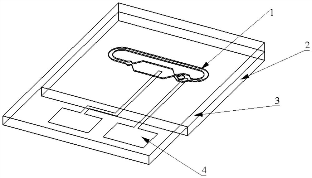
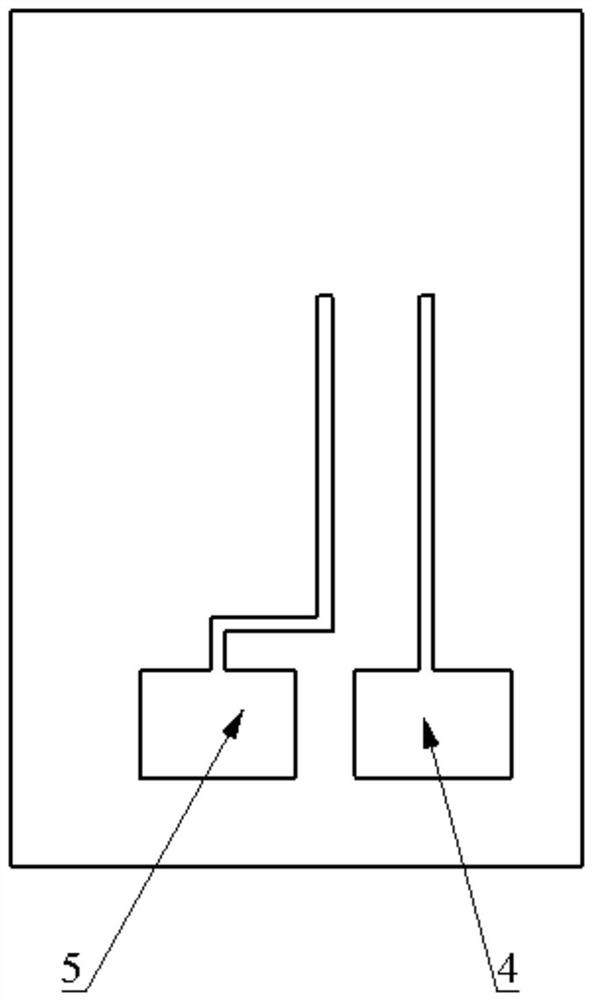
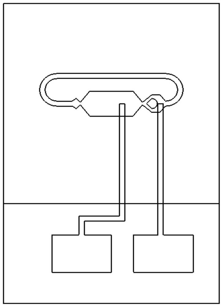
[0038] to combine Figure 1-4 , a bidirectionally identifiable microfluidic inertial switch of the present invention includes a microchannel 1, a substrate 2, a cover plate 3, a metal electrode 4, and metal droplets; the microchannel 1 is arranged on the substrate 2; the The seal between the base 2 and the cover plate 3 prevents metal droplets from splashing out of the microchannel; the microchannel includes a rectangular liquid reservoir 6, a first capillary valve 7, a second capillary valve 8, a third capillary valve 10, The fourth capillary valve 17, the fifth capillary valve 18, the first straight road 9, the second straight road 13, the third straight road 15, the fan-shaped island 11, the first bend 12, the second bend 14, the rhombus passage 16; The metal droplet is located in the rectangular liquid reservoir 6;

[0039] The right end...


PUM


Abstract

The invention discloses a bidirectionally identifiable microfluid inertial electric switch, which comprises a base, a cover plate, metal droplets, metal electrodes and microchannels. The cover plate is located at the upper end of the base, and the two are sealed; the microchannel is arranged on the base; the metal electrode is arranged on the cover plate; Valves, straight channels and bends; the metal droplet is located in a rectangular reservoir. One end contact of the metal electrode is located in the microchannel, and the other end contact is located outside the overlapping area of ​​the base and the cover plate. When the inertial force on the switch is greater than its threshold, the metal droplet will break through the capillary valve. After the recoil load and service load disappear, the metal droplet can completely return to the rectangular liquid storage pool. Under the action, the metal droplet conducts the switch and is irreversible. The invention can bidirectionally identify the acceleration load, stably connect electricity, and has the performance of working in a low temperature environment.

Description

technical field [0001] The invention belongs to the technical field of microfluidic chips, in particular to a bidirectionally identifiable microfluid inertial switch. Background technique [0002] The microfluidic inertial switch is a new type of inertial switch proposed on the basis of microfluidic technology and new material technology. The traditional micromechanical inertial switch is generally composed of a cantilever beam and a mass-spring system, and the switch is turned on through the "solid-solid" contact of the mechanical contact; Instability and other problems reduce the reliability of the switch. The microfluidic inertial switch can effectively avoid such shortcomings. Microfluidic inertial contact switches generally use liquid metal as the working fluid. When the switch is subjected to an acceleration greater than its threshold, the working fluid will reach the position of the fixed signal electrode through the microchannel, and then turn on the switch. [00...

Claims


Application Information

Patent Timeline
Patent Type & Authority Patents(China)
IPC IPC(8): H01H29/00H01H29/04
CPCH01H29/002H01H29/04
Inventor 聂伟荣张润铎朱恒伯
Owner NANJING UNIV OF SCI & TECH
Why Eureka
Try Eureka