Backlight source assembly and backlight module

A backlight module and backlight technology, applied in optics, nonlinear optics, instruments, etc., to achieve the effect of improving dark lines or aperture

Pending Publication Date: 2020-02-07
AU OPTRONICS CORP
View PDF10 Cites 0 Cited by
  • Summary
  • Abstract
  • Description
  • Claims
  • Application Information

AI Technical Summary

Problems solved by technology

However, there is still room for improvement in the effect of printing black dots or changing the lens design

Method used


Image

  • Backlight source assembly and backlight module
  • Backlight source assembly and backlight module
  • Backlight source assembly and backlight module

Examples


Embodiment Construction

[0052] Below in conjunction with accompanying drawing, structural principle and working principle of the present invention are specifically described:

[0053] In the drawings, the widths of some elements, regions, etc. are exaggerated for clarity. Like reference numerals refer to like elements throughout the specification. It will be understood that when an element is referred to as being “on” or “connected to” another element, it can be directly on or connected to the other element or intervening elements may also be present. In contrast, when an element is referred to as being "directly on" or "directly connected to" another element, there are no intervening elements present.

[0054] It should be understood that although the terms "first", "second", "third" etc. may be used throughout the specification to describe various elements, components, regions or sections. But these elements, parts, regions, and / or sections should not be limited by these terms. These terms are o...


PUM


Abstract

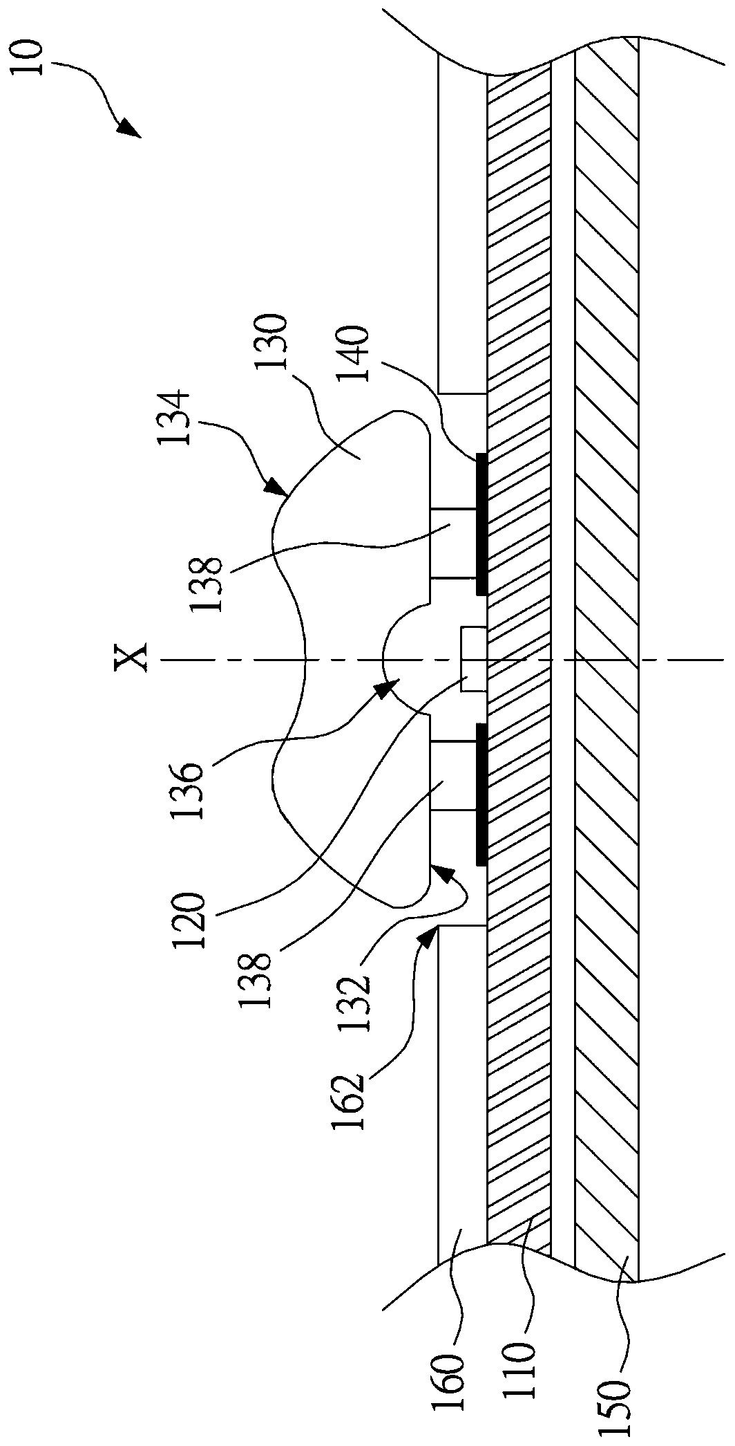
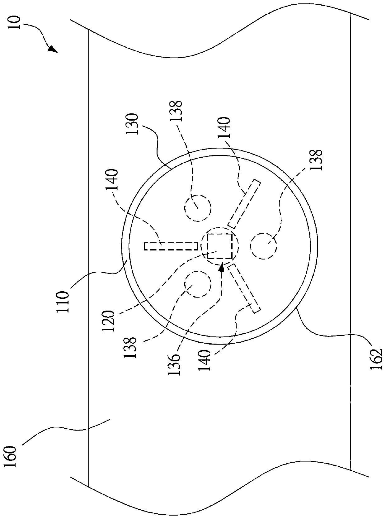
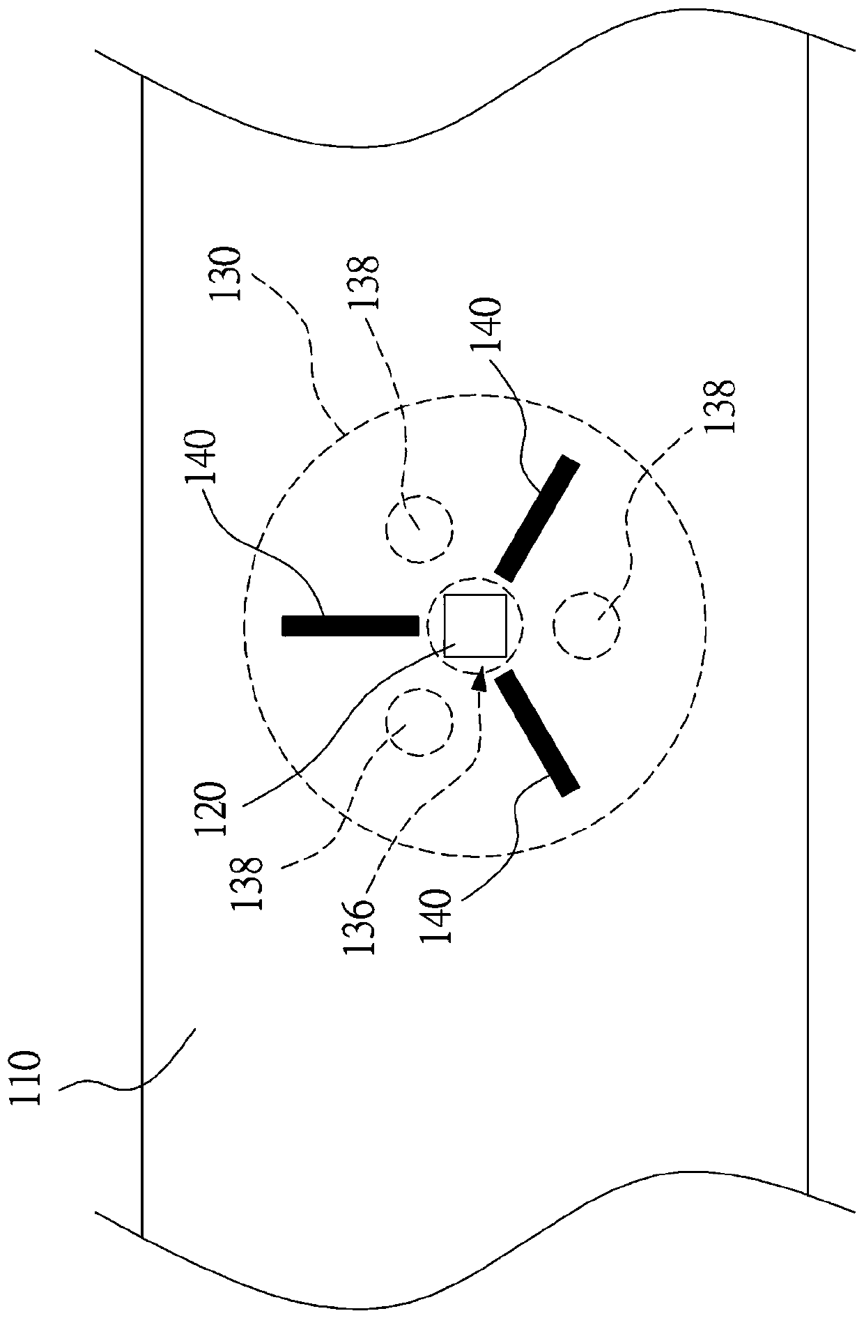
A backlight assembly includes a substrate, a light-emitting element, a lens, and at least one light-absorbing element. The light emitting element is provided on the substrate to emit light on the substrate. The lens is disposed on the substrate and covers the light emitting element. The lens has a main axis, a light incident side, and a light exit side. The main axis passes through the centers ofthe light-entry side and the light-exit side. The main shaft passes through the light-emitting element, and the light-incident side faces the substrate to receive light from the light-emitting element. The light absorbing element is a light absorbing material at least on the surface portion. The light absorbing element is based on the main axis, and the radiation is symmetrically arranged around the light emitting element. The light absorbing element is located within the projection range of the lens on the substrate.

Description

technical field [0001] The invention relates to the design of the direct-lit backlight for liquid crystal panels, in particular to a backlight assembly and a backlight module. Background technique [0002] In the direct-type backlight module used for the backlight of the liquid crystal panel, light-emitting diodes (LEDs) are used as point light sources, and light is projected on the arrayed reflective sheets. An optical lens is further provided on the point light source to change the light path and convert the point light source into a uniform backlight. However, lens settings tend to cause halos or dark fringes on the outside of the lens or above the lens, resulting in uneven brightness. [0003] The current improvement method is to print black dots on the substrate under the lens or change the lens design to improve the aperture or dark lines. However, there is still room for improvement in the effect of printing black dots or changing the lens design. Contents of the ...

Claims


Application Information

Patent Timeline
IPC IPC(8): G02F1/13357
CPCG02F1/133606G02F1/133611G02F1/133607
Inventor 陈建民
Owner AU OPTRONICS CORP
Why Eureka
Try Eureka