Eureka AIR delivers breakthrough ideas for toughest innovation challenges, trusted by R&D personnel around the world.

Display device and driving method thereof

A display device and display area technology, which is applied to static indicators, instruments, etc., can solve the problems of increasing the number of optical component setting areas, destroying the integrity of the display screen, and adversely affecting the display continuity, so as to improve the display continuity and realize the Full screen design to improve display performance

Active Publication Date: 2022-07-26
WUHAN TIANMA MICRO ELECTRONICS CO LTD
View PDF11 Cites 0 Cited by
  • Summary
  • Abstract
  • Description
  • Claims
  • Application Information

AI Technical Summary

Problems solved by technology

With the continuous improvement of users' requirements for imaging quality, the number of cameras installed in the display device is also increasing. However, based on the current camera setting method, one optical component setting area can only correspond to one camera, which leads to The number of optical component placement areas has also increased
Since there is no screen display in the optical component setting area, more optical component setting areas will have a negative impact on the display continuity, destroy the integrity of the display screen, and also limit the design of the full screen

Method used


Image

  • Display device and driving method thereof
  • Display device and driving method thereof
  • Display device and driving method thereof

Examples


Embodiment Construction

[0028] In order to better understand the technical solutions of the present invention, the embodiments of the present invention are described in detail below with reference to the accompanying drawings.

[0029] It should be understood that the described embodiments are only some, but not all, embodiments of the present invention. Based on the embodiments of the present invention, all other embodiments obtained by those of ordinary skill in the art without creative efforts shall fall within the protection scope of the present invention.

[0030] The terms used in the embodiments of the present invention are only for the purpose of describing specific embodiments, and are not intended to limit the present invention. As used in the embodiments of the present invention and the appended claims, the singular forms "a," "the," and "the" are intended to include the plural forms as well, unless the context clearly dictates otherwise.

[0031] It should be understood that the term "an...


PUM


Abstract

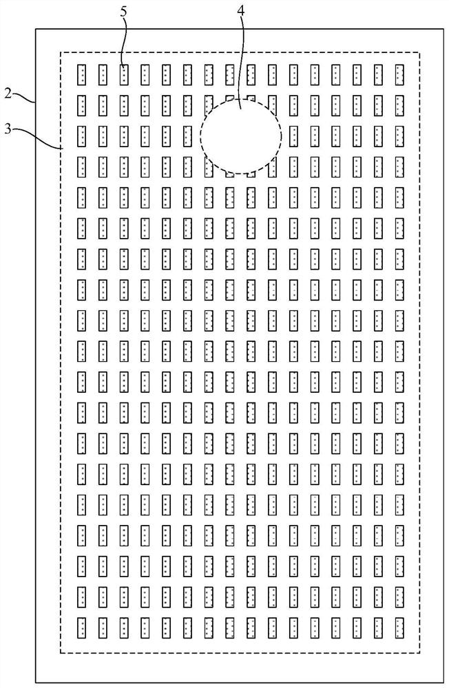
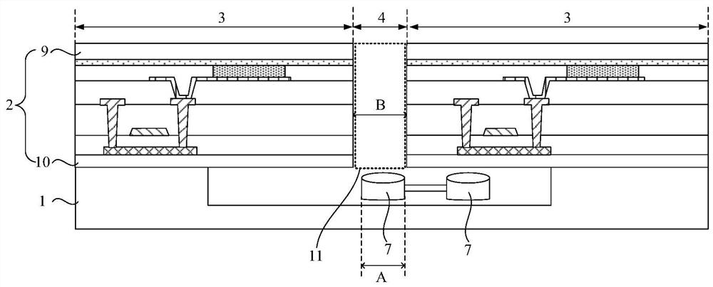
Embodiments of the present invention provide a display device and a driving method thereof, which relate to the field of display technology and can not only improve display continuity, but also better realize full-screen design. The above-mentioned display device includes: a casing; a display panel, the display panel is installed in the casing, the display panel includes a display area and at least one optical component setting area, the display area surrounds the optical component setting area, the display area is provided with pixels, and the optical component setting area No pixel is provided in the interior; at least one camera group, the camera group corresponds to the optical component setting area one-to-one, the camera group includes at least two cameras, the cameras are installed in the housing, and the cameras are located on a side of the display panel facing away from the light-emitting surface of the display device. The controller is used for controlling at least part of the cameras in the camera group to move to the optical component setting area when the display device is in the camera mode, to collect images respectively, and to synthesize the collected images.

Description

【Technical field】 [0001] The present invention relates to the field of display technology, and in particular, to a display device and a driving method thereof. 【Background technique】 [0002] A display device with a camera function includes a display panel and a camera, the display panel includes an optical component setting area and a display area surrounding the optical component setting area, wherein the optical component setting area corresponds to the setting position of the camera and is not used for screen display. With the continuous improvement of users' requirements for image quality, the number of cameras set in the display device is also increasing. However, based on the current camera setting method, one optical component setting area can only correspond to one camera, which leads to The number of optical component placement areas also increases. Since there is no screen display in the optical component setting area, a large number of optical component setting ...

Claims


Application Information

Patent Timeline
Patent Type & Authority Patents(China)
IPC IPC(8): G09G3/20
CPCG09G3/20
Inventor 唐岳军王永志彭涛
Owner WUHAN TIANMA MICRO ELECTRONICS CO LTD
Why Eureka
Eureka Blog
Learn More