
Heavy-current crowned spring jack

A high-current, crown spring technology, applied in the direction of circuits, electrical components, contact parts, etc., can solve the problems of small clamping force of the crown spring socket, arcing, pin loosening, etc., to enhance the clamping force, increase Insertion life, not easy to loose effect

Pending Publication Date: 2020-02-14
DONGGUAN C C P CONTACT PROBES
View PDF0 Cites 0 Cited by
  • Summary
  • Abstract
  • Description
  • Claims
  • Application Information

AI Technical Summary

Problems solved by technology

However, the gap between the inner cylinder and the crown spring causes only the holding force provided by the crown spring after the pin is inserted, so the holding force of the socket of this crown spring is small, especially in the case of vibration, it is easy to cause the pin to loosen and occur. draw arc
In addition, this kind of crown spring socket also has the defect of short plug life

Method used


Image

  • Heavy-current crowned spring jack
  • Heavy-current crowned spring jack
  • Heavy-current crowned spring jack

Examples


Embodiment Construction

[0022] In order to describe the technical content and structural features of the present invention in detail, further description will be given below in conjunction with the implementation and accompanying drawings.

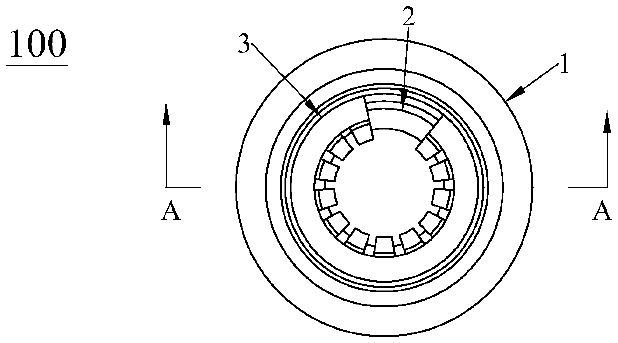
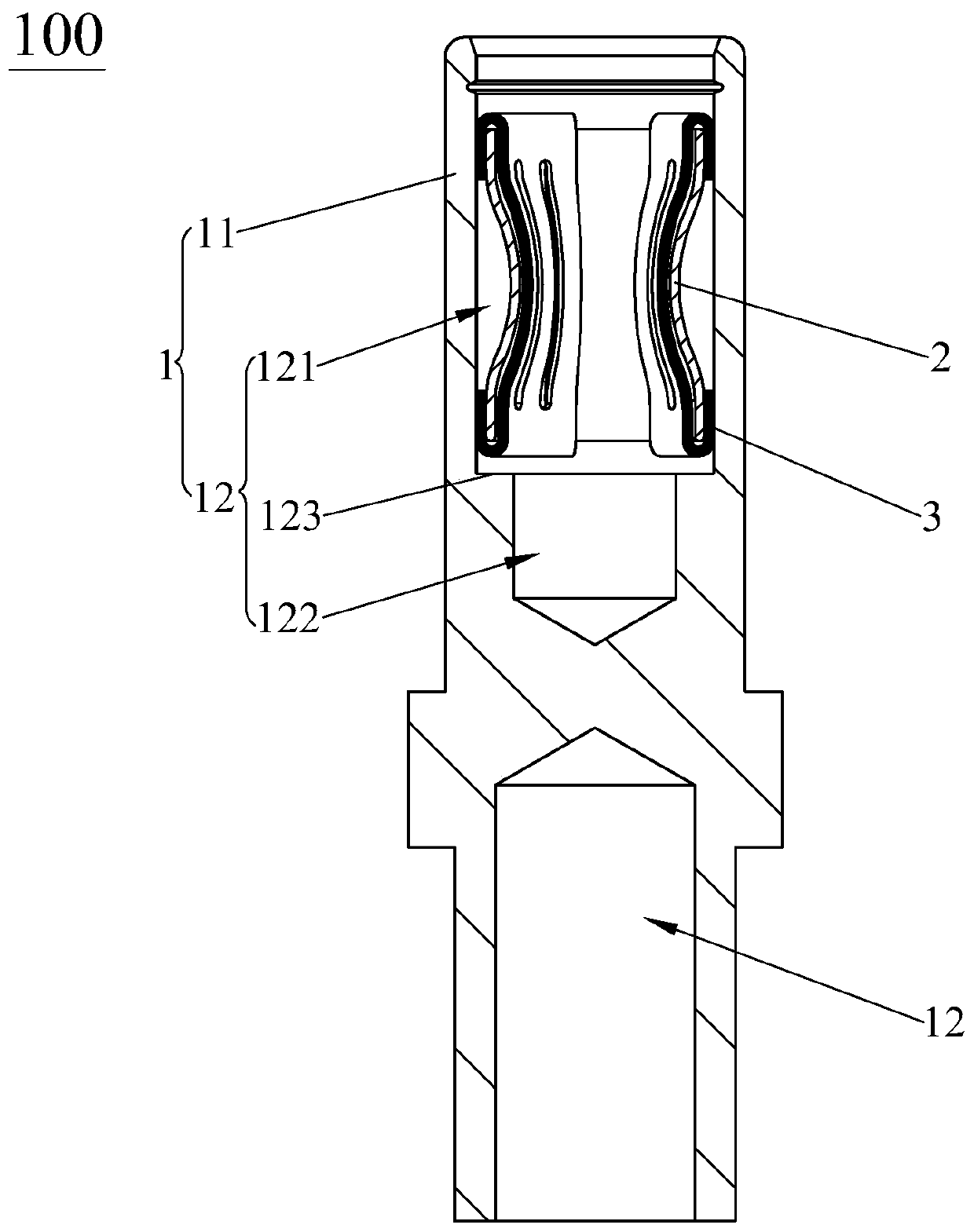
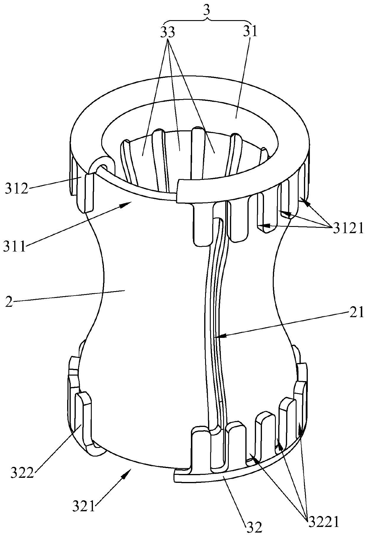
[0023] see Figure 1 to Figure 4 , The high-current crown spring socket 100 of the present invention includes an outer cylinder 1 , an inner cylinder 2 and a crown spring 3 sequentially from outside to inside. The crown spring 3 includes a front end ring 31, a rear end ring 32 and a reed 33 connected between the front end ring 31 and the rear end ring 32. The front end ring 31 and the rear end ring 32 are each provided with a fracture that makes the head and tail are disconnected. 311, 321, by means of the fractures 311, 321, the crown spring 3 is easily deformed, so that it is convenient to install into the inner cylinder 2. The fracture 311 of the front end ring 31 and the fracture 321 of the rear end ring 32 are arranged opposite to each other, which is condu...


PUM


Abstract

The invention discloses a heavy-current crowned spring jack, which successively includes an outer cylinder, an inner cylinder and a crowned spring from the outside to the inside. The crowned spring includes a front end ring, a rear end ring and reeds connected between the front end ring and the rear end ring. The front end ring and the rear end ring are provided with fractures that make the headsand tails of the front end ring and the rear end ring to be disconnected. The reeds are arranged at intervals along the circumferential direction of the front end ring. All the reeds are concave toward the center line of the outer cylinder to enclose a waist-shaped structure. The inner cylinder is tightly attached to the crowned spring. The front end ring and the rear end ring are tightly attachedto the inner side wall of the outer cylinder. The inner cylinder has a trend to holding the crowned spring tightly. Compared with the prior art, the invention has the following beneficial effects: after a pin enters, the inner cylinder holds the crowned spring tightly, the crowned spring then holds the pin tightly, so that the holding force on the pin is enhanced and then the pin is not easy to loosen and the heavy current crowned spring jack is especially applicable to oscillating occasions; in addition, with the help of this trend of the inner cylinder body, the insertion and extraction life of the heavy-current crowned spring jack of the invention is greatly prolonged.

Description

technical field [0001] The invention relates to the field of electrical connectors, in particular to a high-current crown spring jack. Background technique [0002] With the development of science and technology and the advancement of humanities, the application of electrical connectors is increasing, and the requirements for the performance and technical content of electrical connectors are getting higher and higher. In addition to meeting the general performance requirements of electrical connectors, the particularly important requirements are The electrical connector must achieve good contact, reliable operation, and convenient maintenance. Whether its operation is reliable or not directly affects the normal operation of the circuit. The crown spring jack is a kind of jack assembly used on electrical connector (ie connector) products. [0003] The existing crown spring socket includes a crown spring, an outer cylinder and an inner cylinder located between the crown sprin...

Claims


Application Information

Patent Timeline
Patent Type & Authority Applications(China)
IPC IPC(8): H01R13/11H01R13/40H01R13/627H01R13/629
CPCH01R13/111H01R13/40H01R13/627H01R13/629
Inventor 蔡宗明杨磊刘坤杰汪智超李尧
Owner DONGGUAN C C P CONTACT PROBES
Learn More