a safety valve

A safety valve and valve body technology, applied in the field of safety valves, can solve the problems of damaged service life of valve core and valve seat sealing surface, machining error, damage of main valve core sealing surface and valve seat, etc., so as to reduce system pressure shock, The effect of avoiding stuck valve phenomenon and prolonging service life

Active Publication Date: 2021-06-15
江苏军源装备制造有限公司
View PDF0 Cites 0 Cited by
  • Summary
  • Abstract
  • Description
  • Claims
  • Application Information

AI Technical Summary

Problems solved by technology

In actual application, processing errors will occur due to the processing of the valve body and guide sleeve. During assembly, due to the accumulation of errors, sometimes the concentricity of the main valve core and the main valve seat will deviate, resulting in insensitive movement of the main valve, resulting in the failure of the safety valve. Open at rated pressure
When the main valve core is opened, impurities will adhere to the sealing surface of the main valve core, which will cause poor sealing of the main valve core when it is closed, and will cause damage to the sealing surface of the main valve core and the valve seat; It will collide with the sealing surface of the valve seat, which will damage the valve core and the sealing surface of the valve seat and affect the service life; when the traditional pilot-operated safety valve is working, the main valve opens and closes rapidly, which will cause a large pressure shock. It will bring a great burden to the system and reduce the service life of the system; the pilot valve used in the existing safety valve is generally in the form of a seat valve, and collision will occur when the pilot valve core and the pilot valve seat are closed, so that the pilot valve core and the pilot valve seat are closed. The sealing surface between the pilot valve seats is damaged, so that the pilot valve opens early when the set pressure is not reached, so that the safety valve cannot work normally

Method used


Image

  • a safety valve
  • a safety valve
  • a safety valve

Examples


Embodiment Construction

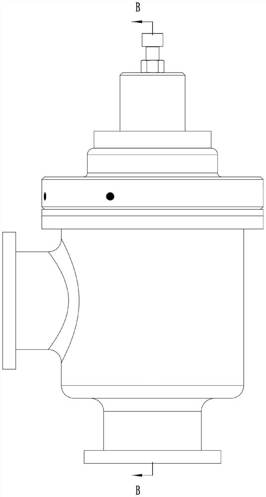
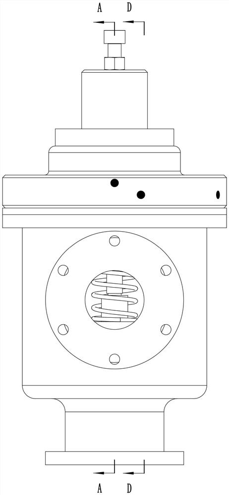
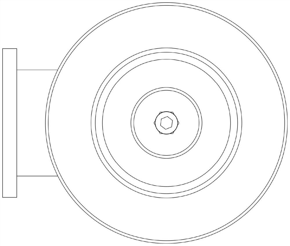
[0036] see Figure 1-20As shown, a safety valve includes a valve body 1, the valve body 1 is provided with a valve chamber 101 with an open upper end, and the peripheral side of the valve body 1 is provided with an outlet pipe 102 communicating with the valve chamber 101. The bottom of the valve body 1 is provided with an inlet pipe 103 communicated with the valve chamber 101; the valve chamber 101 is provided with a main valve seat 104 for separating the inlet pipe 103 and the outlet pipe 102; the upper opening of the valve chamber 101 is fixed A bonnet 6 is installed, and the center position of the bonnet 6 is provided with a gear groove 61 with an upper end opening, and the bottom center position of the gear groove 61 is provided with a through hole 62; the inner edge of the bonnet 6 is perpendicular to the rotation The axial direction of the hole 62 is provided with a through plunger hole 63, and the plunger hole 63 communicates with the gear groove 61; the main control ro...


PUM


Abstract

The invention discloses a safety valve, comprising a valve body, the valve body is provided with a valve chamber with an upper end opening, the valve body is provided with an outlet pipe and an inlet pipe; the valve chamber is provided with a main valve seat; The upper opening of the valve cavity is fixed with a bonnet, the bonnet is provided with a gear groove with an upper opening, and the bottom of the gear groove is provided with a rotating hole for passing through the pipe; the bonnet is provided with a through plunger hole; The main control rod is connected to the hole in rotation, and the lower end of the main control rod is connected to the main valve seat in rotation; the main control rod is provided with a power gear; the plunger hole is slidingly connected to a rack rod; A valve hole, the main valve core is fixedly installed on the main control rod, and the second valve port is arranged on the main valve core; the first spring is sleeved on the main control rod; the pilot valve assembly is arranged on the valve cover; The safety valve not only has a simple structure, but also avoids the jamming phenomenon of the main valve core due to the accumulation of processing errors; at the same time, it can also avoid the collision between the main valve core and the main valve seat when opening and closing.

Description

technical field [0001] The invention belongs to the technical field of valves, and in particular relates to a safety valve. Background technique [0002] Pilot-operated safety valves are mainly used in petroleum, chemical industry, electric power, metallurgy and other fields, and are the best overpressure protection devices on pressurized equipment, containers or pipelines. In actual application, processing errors will occur due to the processing of the valve body and guide sleeve. During assembly, due to the accumulation of errors, sometimes the concentricity of the main valve core and the main valve seat will deviate, resulting in insensitive movement of the main valve, resulting in the failure of the safety valve. Open at rated pressure. When the main valve core is opened, impurities will adhere to the sealing surface of the main valve core, which will cause poor sealing of the main valve core when it is closed, and will cause damage to the sealing surface of the main va...

Claims


Application Information

Patent Timeline
Patent Type & Authority Patents(China)
IPC IPC(8): F16K17/10F16K17/164F16K31/36
CPCF16K17/10F16K17/164F16K31/36
Inventor 黄延军邵玉刚
Owner 江苏军源装备制造有限公司
Why Eureka
Try Eureka