a safety valve

A safety valve and valve body technology, applied in the field of safety valves, can solve problems such as damage to the sealing surface of the valve core and valve seat, processing errors, and impact on service life, so as to reduce system pressure shock, avoid stuck valve phenomenon, and prolong service life Effect

Active Publication Date: 2021-06-01
ZHEJIANG KADA VALVE
View PDF7 Cites 0 Cited by
  • Summary
  • Abstract
  • Description
  • Claims
  • Application Information

AI Technical Summary

Problems solved by technology

In actual application, processing errors will occur due to the processing of the valve body and guide sleeve. During assembly, due to the accumulation of errors, sometimes the concentricity of the main valve core and the main valve seat will deviate, resulting in insensitive movement of the main valve, resulting in the failure of the safety valve. Open at rated pressure
When the main valve core is opened, impurities will adhere to the sealing surface of the main valve core, which will cause poor sealing of the main valve core when it is closed, and will cause damage to the sealing surface of the main valve core and the valve seat; It will collide with the sealing surface of the valve seat, which will damage the valve core and the sealing surface of the valve seat and affect the service life; when the traditional pilot-operated safety valve is working, the main valve opens and closes rapidly, which will cause a large pressure shock. It will bring a great burden to the system and reduce the service life of the system; the pilot valve used in the existing safety valve is generally in the form of a seat valve, and collision will occur when the pilot valve core and the pilot valve seat are closed, so that the pilot valve core and the pilot valve seat will collide. The sealing surface between the pilot valve seats is damaged, so that the pilot valve opens early when the set pressure is not reached, so that the safety valve cannot work normally

Method used


Image

  • a safety valve
  • a safety valve
  • a safety valve

Examples


Embodiment Construction

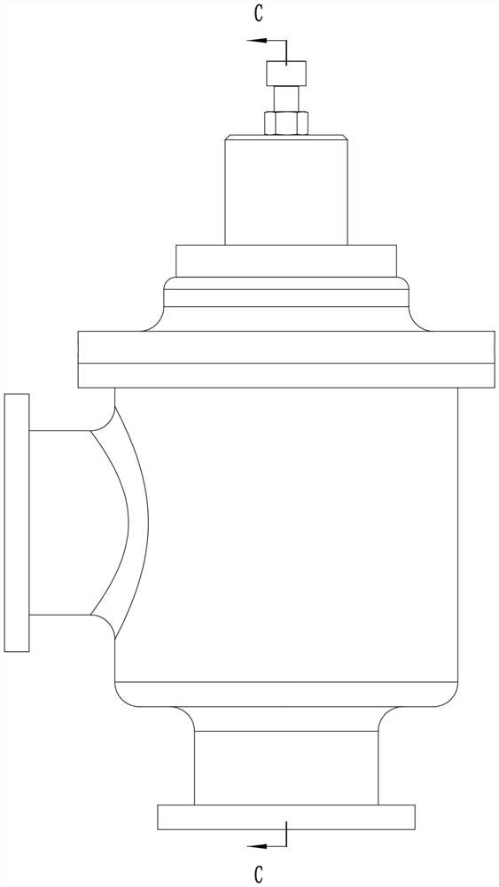
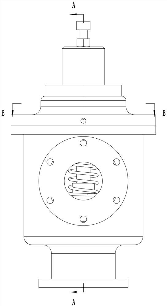
[0034] see Figure 1-15 As shown, a safety valve includes a valve body 1, the valve body 1 is provided with a valve chamber 101 with an open upper end, and the peripheral side of the valve body 1 is provided with an outlet pipe 102 communicating with the valve chamber 101. The bottom of the valve body 1 is provided with an inlet pipe 103 communicated with the valve chamber 101; the valve chamber 101 is provided with a main valve seat 104 for separating the inlet pipe 103 and the outlet pipe 102; the upper opening of the valve chamber 101 is fixed A valve cover 6 is installed, and the valve cover 6 is provided with a vertically downwardly extending sleeve 601 on the face facing the inlet pipe 103; The first valve hole 1c, the main valve core 2 is rotatably connected to the sleeve 601, and the second valve hole 2b is arranged on the main valve core 2; the first spring 5 is sleeved on the sleeve 601, so The first spring 5 is located between the valve cover 6 and the main valve c...


PUM


Abstract

The invention discloses a safety valve, comprising a valve body, the valve body is provided with a valve chamber with an open upper end, the circumferential side of the valve body is provided with an outlet pipe communicating with the valve chamber, and the bottom of the valve body is provided with An inlet pipe communicating with the valve cavity; a main valve seat is provided in the valve cavity; a valve cover is fixedly installed at the upper opening of the valve cavity, and the valve cover is provided with a sleeve extending vertically downward; the A first spring is sleeved on the sleeve; a main control rod is slidably connected to the inside of the sleeve, a vertical chute is provided on the sleeve, and a first A spiral groove, a first boss is provided on the circumferential side of the main control rod; a second spring is provided in the sleeve; a pilot valve assembly is provided in the valve cover; the safety valve is not only simple in structure, but also avoids the main The stuck phenomenon of the spool due to the accumulation of processing errors; at the same time, it can also avoid the collision between the main spool and the main valve seat when opening and closing.

Description

technical field [0001] The invention belongs to the technical field of valves, and in particular relates to a safety valve. Background technique [0002] Pilot-operated safety valves are mainly used in petroleum, chemical industry, electric power, metallurgy and other fields, and are the best overpressure protection devices on pressurized equipment, containers or pipelines. In actual application, processing errors will occur due to the processing of the valve body and guide sleeve. During assembly, due to the accumulation of errors, sometimes the concentricity of the main valve core and the main valve seat will deviate, resulting in insensitive movement of the main valve, resulting in the failure of the safety valve. Open at rated pressure. When the main valve core is opened, impurities will adhere to the sealing surface of the main valve core, which will cause poor sealing of the main valve core when it is closed, and will cause damage to the sealing surface of the main va...

Claims


Application Information

Patent Timeline
Patent Type & Authority Patents(China)
IPC IPC(8): F16K17/06F16K17/164
CPCF16K17/06F16K17/164
Inventor 黄延军邵玉刚
Owner ZHEJIANG KADA VALVE
Why Eureka
Try Eureka