Fluid end of vertical combination valve

A combination valve and hydraulic end technology, applied in the field of reciprocating pumps, can solve the problems of unreasonable front-end connection, affecting the force of the frame, and increasing the number of wearing parts of the pump valve. Influence and improve the effect of sealing effect

Active Publication Date: 2018-11-27
宝鸡市三泉泵业制造有限公司
View PDF12 Cites 0 Cited by
  • Summary
  • Abstract
  • Description
  • Claims
  • Application Information

AI Technical Summary

Problems solved by technology

This simple vertical installation of the conventional combined valve has brought new problems (1) The suction port of the conventional combined valve is very close to the discharge port in the middle of the valve seat, and the pipeline layout of the pump body after the vertical installation of the combined valve is very poor. Convenient, especially the suction pipe and discharge pipe are arranged on the upper part of the plunger, which affects maintenance
(2) Most of the pump body is on the upper part of the plunger (that is, on the center line of the plunger), and the connection between the pump body and the front end of the frame is unreasonable, which affects the force on the frame
However, this solution only solves the problem of the outflow area of ​​the valve plate and does not solve the problem of the inflow area of ​​the valve seat hole. If the flow in from the valve seat hole is not large enough, the outflow is meaningless
At the same time, for combined valves installed horizontally, reducing the guide contact surface will cause more serious problems of the valve plate sinking and eccentric wear due to its own weight
Invention patent 201610503627.8 "Reciprocating Pump Liquid Cylinder" uses two sets of conventional combination valves to be installed vertically and work at the same time to double the flow rate to achieve the goal of 1+1=2. This solution doubles the number of pump and valve wearing parts. The size of the pump body will also be greatly increased, and the piping layout will be more difficult
However, the contact surface between the rectangular braided packing and the plunger is wide, and only a few lines of contact or very narrow surface contact are actually used for sealing. The friction between multiple rectangular braided packing and the plunger will produce a lot of wear debris due to the wide contact surface. Abrasive debris is sandwiched between the plunger and the seal, which causes rapid wear of the plunger. More importantly, it is affected by the strength of the seal packing. The commonly used braided packing has a large section size, such as 8×8, 10×10, 12×12 , 15×15, etc., the inner hole of the braided packing will be scrapped after wear and tear, and the discarded braided packing will cause great environmental pollution and waste of resources; moreover, when the plunger seal assembly is replaced, the plunger must be removed, which is very costly time

Method used


Image

  • Fluid end of vertical combination valve
  • Fluid end of vertical combination valve
  • Fluid end of vertical combination valve

Examples


Embodiment 1

[0043] This embodiment provides a fluid end of a vertical combined valve.

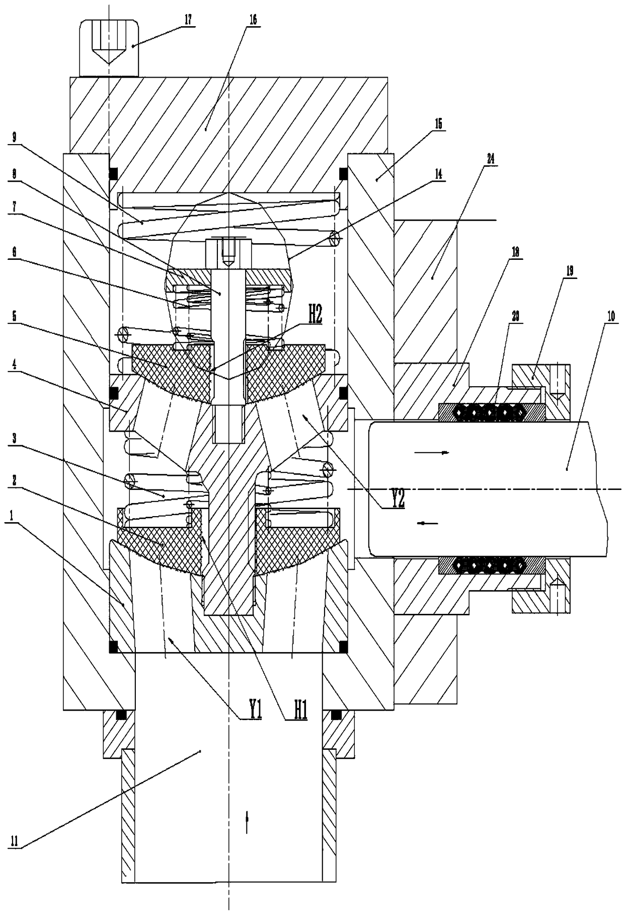
[0044] The hydraulic end of the vertical combination valve of the present invention consists of a suction valve seat 1, a suction valve plate 2, a suction spring 3, a discharge valve seat 4, a discharge valve plate 5, a discharge spring 6, a discharge valve spring seat 7, and a discharge valve plate guide rod 8 , Compression spring 9, valve gland 16, pump body 15, stuffing box 18, plunger 10, plunger seal 20, adjustment nut 19 components. The suction valve seat hole Y1 and the discharge valve seat hole Y2 are not on the same circumferential section; the discharge valve seat 4 is provided with a guide rod part that guides the suction valve plate 2, and the suction valve plate 2 is formed by the guide rod part on the discharge valve seat 4. Guided, the guide rod portion on the suction valve plate 2 and the discharge valve seat 4 and the discharge valve plate 5 and the discharge valve guide rod 8 are alwa...

Embodiment 2

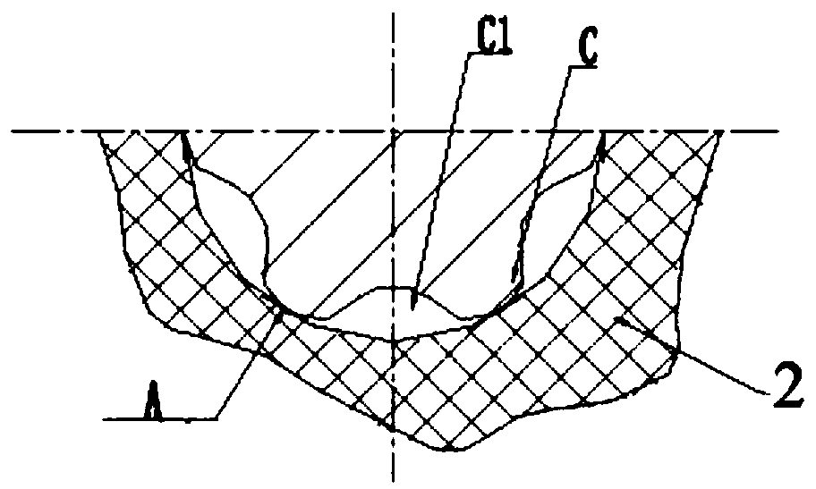
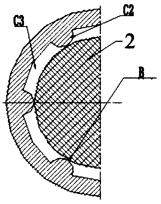
[0052] Such as Figure 4 Shown is another embodiment of the hydraulic end vertical combination valve part of the vertical combination valve of the present invention, which is figure 1 Another deformation structure of the discharge valve seat, that is, the figure 1 The guide rod at the bottom of the discharge valve seat 4 becomes the guide cylinder at the bottom of the discharge valve seat 4, and the guide of the suction valve plate 2 changes from the inner arc hole H1 to the outer arc H2. The guide cylinder at the lower part of the discharge valve seat 4 is connected with the suction valve seat 1, there is an arc H2 on the outer circle of the suction valve plate 2, and there are several inner holes of the guide cylinder at the lower part of the discharge valve seat 4 guided by the arc H12 of the suction valve plate 2 Small arc C2 and groove C3, such as image 3 As shown, there are several contact points B on the contact section to ensure that when the suction valve plate 2 m...

Embodiment 3

[0054] Such as Figure 5 Shown is another embodiment of the hydraulic end vertical combined valve part of the vertical combined valve of the present invention, the discharge valve seat 4 and the suction valve seat 1 are integrally arranged valve seats 12, and the lower part is matched with the suction valve plate 2 The sealing surface has the suction valve seat hole Y1, the upper part is the sealing surface matched with the discharge valve plate 5, and has the discharge valve seat hole Y2, the middle part of the cylinder is used to guide the suction valve plate 2, and the structure of the guide part is the figure 1 are basically the same. The discharge valve plate 5 and the discharge valve spring 6 are placed inside the discharge valve cover 13, the outer circle of the discharge valve plate 5 and the guide of the discharge valve cover 13 Figure 4 The guide structure of the suction valve plate 2 and the lower part of the discharge valve seat 4 is basically the same, and the ...


PUM


Abstract

The invention discloses a fluid end of a vertical combination valve. The fluid end of a vertical combination valve comprises a valve assembly and a plunger seal assembly, wherein the suction valve seat hole and the discharge valve seat hole are not on the same circumferential section; the discharge valve seat is provided with a guide rod part used for guiding the suction valve plate, the suction valve plate is guided by a guide rod part on the discharge valve seat, the suction valve plate and the guide rod part on the discharge valve seat, and the discharge valve plate and the discharge valveguide rod are always contacted with a plurality of points on any contact section in the process of valve plate movement. The fluid end of the vertical combination valve can be used at large flow, hasgood sealing effect of the valve group, moreover, is convenient to assemble and disassemble, does not deform in assembly use, facilitates the arrangement of the suction and discharge pipeline, reducesthe size of the pump body, and ensures the reliable connection between the pump body and the frame; the diamond-shaped packing seal component not only reduces the consumption of the braided packing but also can be reliably sealed, and rapidly replace the packing seal.

Description

technical field [0001] The invention relates to the technical field of reciprocating pumps, in particular to a fluid end of a vertical combination valve. Background technique [0002] The key components in the liquid end of the reciprocating pump are also the main vulnerable parts are the valve assembly and the plunger seal assembly. Among conventional valve components, combination valves are widely used in reciprocating pumps because of their convenient processing and disassembly. But the common combination valve is basically a combination valve installed horizontally, that is, the movement direction of the valve plate is the same as that of the plunger. The combined valve installed horizontally will sink due to the influence of the weight of the valve plate and spring, resulting in deflection, which will easily cause the guide of the valve plate to be eccentrically worn, and then cause poor sealing. At the same time, because the suction channel and discharge channel of t...

Claims


Application Information

Patent Timeline
IPC IPC(8): F04B53/10F04B53/14
CPCF04B53/109F04B53/1092F04B53/143
Inventor 马远志
Owner 宝鸡市三泉泵业制造有限公司
Why Eureka
Try Eureka