
Amphibious landing unmanned aerial vehicle

An amphibious and unmanned aerial vehicle technology, applied in the field of unmanned aerial vehicles, can solve the problems of not being able to land on the water surface, unmanned aerial vehicles lost at the bottom of the lake, and a single landing location, so as to ensure stability and safety, increase landing stability, and increase stability. Effect

Inactive Publication Date: 2020-02-28
季元吉
View PDF0 Cites 5 Cited by
  • Summary
  • Abstract
  • Description
  • Claims
  • Application Information

AI Technical Summary

Problems solved by technology

[0005] Aiming at the deficiencies of the prior art, the present invention provides an amphibious landing UAV, which can land on the water surface or land, which expands the scope of use of the UAV, and increases the number of landing locations. The diversity of drone operations also prevents the drone from being unable to land due to failures when flying over the water, causing the drone to be lost at the bottom of the lake or completely scrapped, reducing property losses, solving the problem of not being able to land on the water surface, and a single landing location The problem

Method used


Image

  • Amphibious landing unmanned aerial vehicle
  • Amphibious landing unmanned aerial vehicle
  • Amphibious landing unmanned aerial vehicle

Examples


Embodiment Construction

[0030] The following will clearly and completely describe the technical solutions in the embodiments of the present invention with reference to the accompanying drawings in the embodiments of the present invention. Obviously, the described embodiments are only some, not all, embodiments of the present invention. Based on the embodiments of the present invention, all other embodiments obtained by persons of ordinary skill in the art without making creative efforts belong to the protection scope of the present invention.

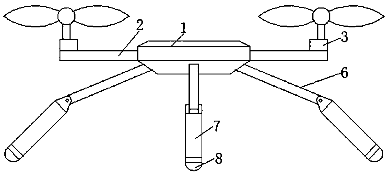
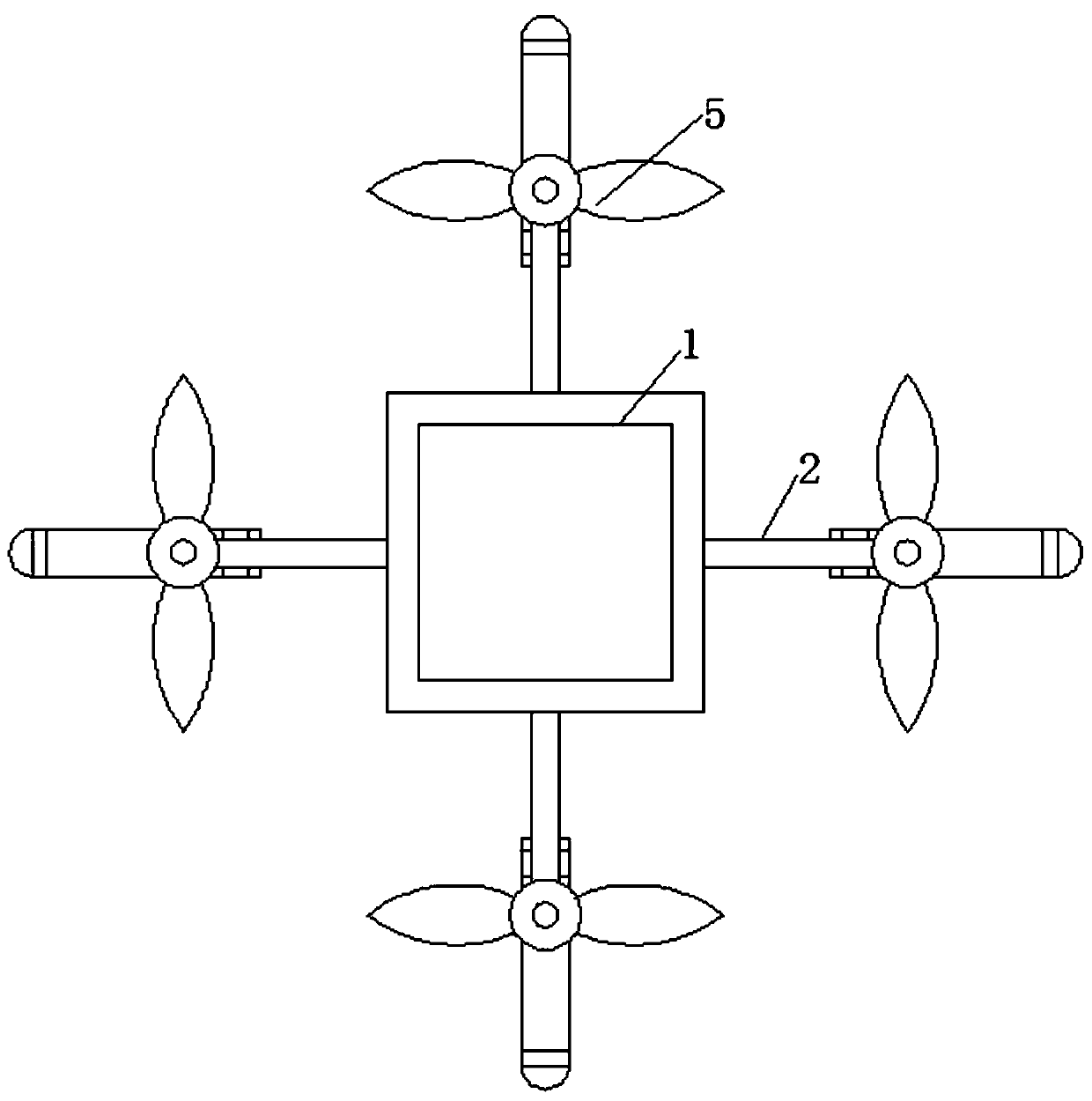
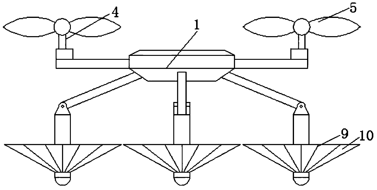
[0031] see Figure 1-6 , an amphibious landing unmanned aerial vehicle, comprising a body 1, the exterior of the body 1 is fixedly connected with an organic arm 2, the top of the machine arm 2 is movably connected with a motor 3, and the top of the motor 3 is movably connected with a rotating shaft 4, and the rotating shaft 4 is far away from the motor One end of 3 is fixedly connected to the wing 5, and there are four arms 2, motor 3, rotating shaft 4 and win...


PUM


Abstract

The invention relates to the technical field of unmanned aerial vehicles, and discloses an amphibious landing unmanned aerial vehicle. The amphibious landing unmanned aerial vehicle comprises a machine body, wherein machine arms are fixedly connected outside the machine body; motors are movably connected to the tops of the machine arms; rotating shafts are movably connected to the tops of the motors; one ends, away from the motors, of the rotating shafts are fixedly connected with wings; a support frame is fixedly connected to the bottom of the machine body; one end, away from the machine body, of the support frame is movably connected with a landing gear; one end, away from the support frame, of the landing gear is fixedly connected with a lifting head; a support rod is movably connectedoutside the landing gear; and an air bag is movably connected outside the support rod. Through the cooperation of the landing gear and the support frame, when the unmanned aerial vehicle lands on land, the landing gear unfolds, so that the landing area of the landing gear is increased, the gravity center of the unmanned aerial vehicle is reduced, and the landing stability of the unmanned aerial vehicle is improved; through the cooperation of the landing gear, the support rod and the air bag, when the unmanned aerial vehicle needs to land on the water, the support rod and the air bag unfold toinflate the air bag, so that the effect of water landing of the unmanned aerial vehicle is achieved.

Description

technical field [0001] The invention relates to the technical field of unmanned aerial vehicles, in particular to an amphibious landing unmanned aerial vehicle. Background technique [0002] Unmanned aerial vehicle, referred to as unmanned aerial vehicle, mainly uses the ground controller to control the flight through wireless sensing technology. It has flexible activities, fast response and low operation requirements, and is widely used. Its main functions are on-site survey, photography, sampling, transportation And so on, often the UAV flies near the river and needs to land on the water surface, or when the UAV fails over the water, the UAV cannot land in time and crashes into the lake. [0003] The problem of the existing UAV landing on land has been solved, but the UAV landing on the water is still not involved. Therefore, when the UAV fails to fly over the water, it will often fall into the lake and be lost, or the UAV will be lost. It is completely scrapped, causing ...

Claims


Application Information

Patent Timeline
Patent Type & Authority Applications(China)
IPC IPC(8): B64C25/32B64C25/56B64C25/04B64C35/00
CPCB64C25/04B64C25/32B64C25/56B64C35/008
Inventor 季元吉
Owner 季元吉
Learn More