Supercharge Your Innovation With Domain-Expert AI Agents!

Heat exchanger fin, heat exchanger, indoor unit and air conditioner

A technology of heat exchangers and fins, which is applied in the field of air conditioners, can solve the problems of affecting the heat exchange efficiency of air conditioners, low utilization rate of heat exchangers, and excess air volume, so as to improve utilization rate, save energy consumption, and reduce waste of materials Effect

Active Publication Date: 2020-02-28
GD MIDEA HEATING & VENTILATING EQUIP CO LTD +1
View PDF5 Cites 5 Cited by
  • Summary
  • Abstract
  • Description
  • Claims
  • Application Information

AI Technical Summary

Problems solved by technology

However, the air sent by the fan of the indoor unit is generally non-uniform, which may easily cause excess air volume in some areas of the heat exchanger and waste of materials in some areas, resulting in low utilization of the heat exchanger and affecting the heat exchange efficiency of the air conditioner.

Method used


Image

  • Heat exchanger fin, heat exchanger, indoor unit and air conditioner
  • Heat exchanger fin, heat exchanger, indoor unit and air conditioner
  • Heat exchanger fin, heat exchanger, indoor unit and air conditioner

Examples


Embodiment 1

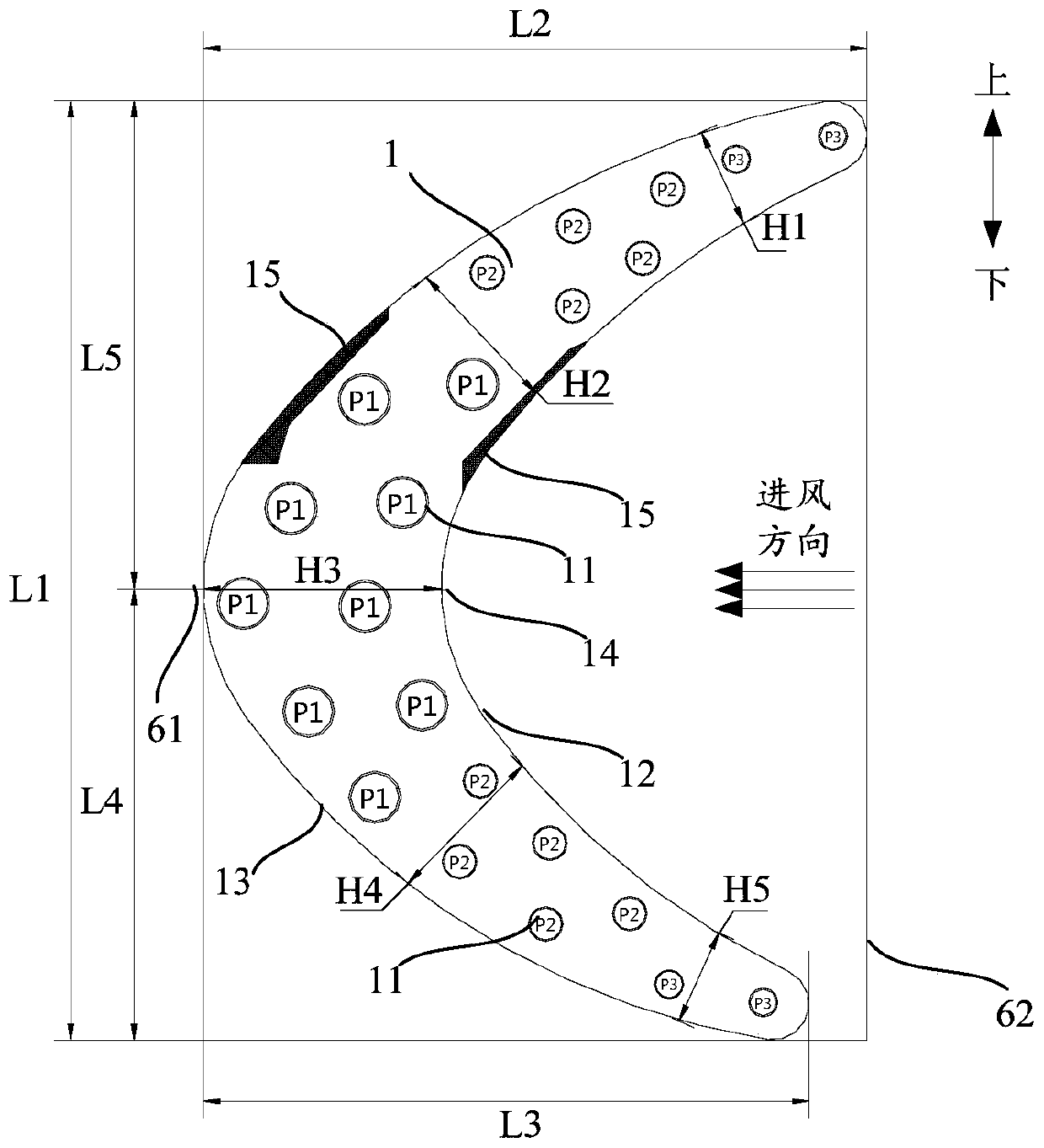
[0064] A heat exchanger fin is provided in this embodiment, such as figure 1 As shown, it includes an integrally formed fin body 1, the fin body 1 includes an air outlet contour 13 on one side and an air inlet contour 12 on the opposite side, and the fin body 1 is provided with A plurality of refrigerant pipe installation holes 11 for installing refrigerant pipes. The fin body 1 is concave along the direction from the air inlet side to the air outlet side, forming a curved shape, on the straight line where the radius of curvature of the air outlet contour line 13 of the fin body 1 is located, or on the air inlet contour line 12 of the fin body 1 On the straight line where the curvature radius of , the distance between the air inlet contour line 12 and the air outlet contour line 13 of the fin body 1 gradually decreases from the middle of the heat exchanger fin to both ends. Correspondingly, the refrigerant pipe installation hole 11 The inner diameter of the heat exchanger fin...

Embodiment 2

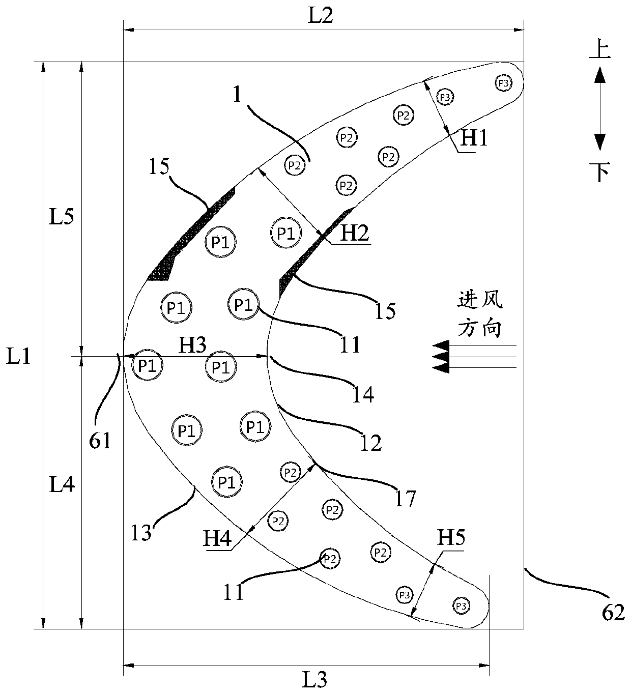
[0066] A heat exchanger fin is provided in this embodiment, such as figure 2As shown, it includes an integrally formed fin body 1, the fin body 1 includes an air outlet contour 13 on one side and an air inlet contour 12 on the opposite side, and the fin body 1 is provided with A plurality of refrigerant pipe installation holes 11 for installing refrigerant pipes. The fin body 1 is concave along the direction from the air inlet side to the air outlet side, forming a curved shape, on the straight line where the radius of curvature of the air outlet contour line 13 of the fin body 1 is located, or on the air inlet contour line 12 of the fin body 1 On the straight line where the curvature radius of , the distance between the air inlet contour line 12 and the air outlet contour line 13 of the fin body 1 gradually decreases from the middle of the heat exchanger fin to both ends. Correspondingly, the refrigerant pipe installation hole 11 The inner diameter of the heat exchanger fin...

Embodiment 3

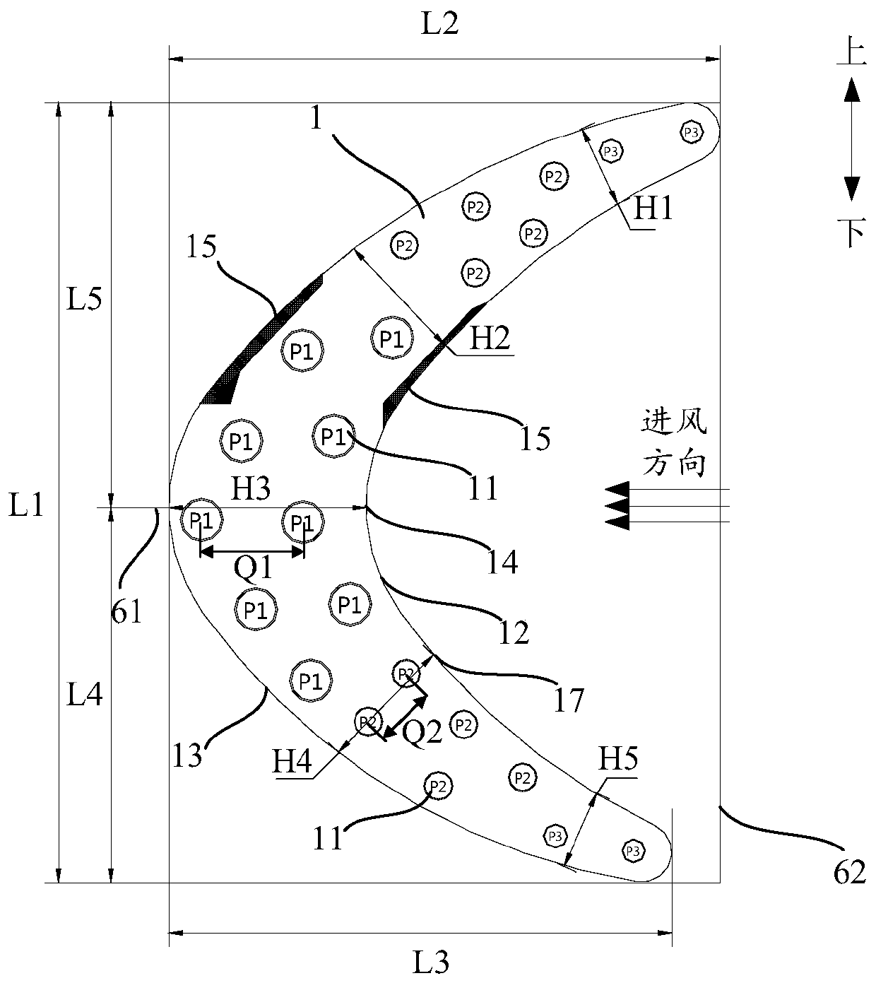
[0068] A heat exchanger fin is provided in this embodiment, such as image 3 As shown, it includes an integrally formed fin body 1, the fin body 1 includes an air outlet contour 13 on one side and an air inlet contour 12 on the opposite side, and the fin body 1 is provided with A plurality of refrigerant pipe installation holes 11 for installing refrigerant pipes. The fin body 1 is concave along the direction from the air inlet side to the air outlet side, forming a curved shape, on the straight line where the radius of curvature of the air outlet contour line 13 of the fin body 1 is located, or on the air inlet contour line 12 of the fin body 1 On the straight line where the curvature radius of , the distance between the air inlet contour line 12 and the air outlet contour line 13 of the fin body 1 gradually decreases from the middle of the heat exchanger fin to both ends. Correspondingly, the refrigerant pipe installation hole 11 The inner diameter of the heat exchanger fin...


PUM


Abstract

The invention provides a heat exchanger fin, a heat exchanger, an indoor unit and an air conditioner. The heat exchanger fin comprises a fin body, the fin body comprises an air outlet contour line onone side and an air inlet contour line on the other side, and the fin body is provided with a plurality of refrigerant pipe mounting holes. On the straight line where the curvature radius of the air outlet contour line of the fin body is located or on the straight line where the curvature radius of the air inlet contour line of the fin body is located, the distance between the air inlet contour line and the air outlet contour line of the fin body is gradually reduced from the middle of the heat exchanger fin to the two ends. The inner diameters of the refrigerant pipe mounting holes are gradually reduced from the middle part of the heat exchanger fin to the two ends. According to the technical scheme, the utilization rate of the heat exchanger fin can be improved, the heat exchange efficiency is improved, the energy consumption is reduced, material waste can be reduced, and the production cost is reduced.

Description

technical field [0001] The invention relates to the technical field of air conditioning, in particular to a heat exchanger fin, a heat exchanger, an indoor unit and an air conditioner. Background technique [0002] At present, the heat exchanger fins commonly used in indoor unit heat exchangers are mostly rectangular with equal width or with some special-shaped structures at both ends of the rectangle, and the pipe flow paths on the heat exchanger fins are evenly arranged according to the law. However, the air sent by the fan of the indoor unit is generally non-uniform, which may easily cause excess air volume in some areas of the heat exchanger and waste of materials in some areas, resulting in low utilization of the heat exchanger and affecting the heat exchange efficiency of the air conditioner. Contents of the invention [0003] The present invention aims to solve at least one of the technical problems existing in the prior art or related art. [0004] Therefore, an o...

Claims


Application Information

Patent Timeline
Patent Type & Authority Applications(China)
IPC IPC(8): F24F1/0067F24F1/0063
CPCF24F1/0063F24F1/0067
Inventor 周柏松罗彬李丰李兆辉杨坤马丽华
Owner GD MIDEA HEATING & VENTILATING EQUIP CO LTD
Features
  • R&D
  • Intellectual Property
  • Life Sciences
  • Materials
  • Tech Scout
  • Unparalleled Data Quality
  • Higher Quality Content
  • 60% Fewer Hallucinations
Learn More