Split type wire clamping structure

A split-type, clamping technology, applied in the direction of electrical components, etc., can solve the problems of off-line, unusable, high cost, etc., and achieve the effect of small installation space, easy installation and high reliability

Active Publication Date: 2020-02-28
CHINA AVIATION OPTICAL-ELECTRICAL TECH CO LTD
View PDF10 Cites 2 Cited by
  • Summary
  • Abstract
  • Description
  • Claims
  • Application Information

AI Technical Summary

Problems solved by technology

[0004] ①Two threaded holes need to be pre-opened for the wiring seat. The spacing of the threaded holes is customized and it is not easy to be compatible with other devices
[0005] ②Silk rope tying has the risk of being off-line, and it needs to be reinforced with glue, but the glue has a long curing period and is not conducive to repairing
[0006] ③It is easy to damage the cable sheath when dismantling
[0007] ④ The space occupied by the fixed wiring seat is relatively large
[0009] ① The wiring needs to be customized according to the space of the equipment casing, which is expensive, and the spacing between the mounting holes is fixed and it is not easy to be compatible with other devices
[0010] ② There is a risk of off-line binding with brocade silk rope, which needs to be reinforced with glue, and the curing period of the glue is longer
[0011] ③It is easy to damage the cable sheath when dismantling
[0012] ④ The space occupied by the fixed line is relatively large
[0014] ①Clamps need to be fastened with screws, and the space occupied by the fasteners cannot be utilized, making them unusable in a narrow space
[0015] ②When borrowing the device mounting hole, since the main body of the clamp is on one side, it is easy to interfere with it, and the versatility is poor

Method used


Image

  • Split type wire clamping structure
  • Split type wire clamping structure
  • Split type wire clamping structure

Examples


Embodiment Construction

[0045] In order to further illustrate the technical means and technical effects adopted by the present invention, the present invention will be described in detail below in conjunction with the examples.

[0046] It should be noted that the orientation-indicating terms such as "bottom", "bottom", and "upper end" in the present invention are all based on the orientation or positional relationship shown in the figure, and are only for the convenience of describing the present invention, so they cannot be understood as Invention Limitations.

[0047] The clamping structure of the present invention includes a base 1 with a cylindrical inner wall and a bottom plate connected thereto. A through hole is opened on the bottom plate 2 of the base so that the fastener 3 can pass through the through hole to fix the base on the mounting plate 4 . The inner wall of the base is equipped with a ring-shaped positioning reed 5 with a tongue. The end of the positioning reed is provided with an o...


PUM


Abstract

The invention relates to a split type wire clamping structure. The structure comprises a base and a cable sleeve matched with the base, wherein the base is fixed on a mounting plate through a fastener, a positioning reed is assembled on an inner wall of the base, an opening at an end of the positioning reed enables the positioning reed to have elasticity so that an outer wall of the positioning reed is tightly attached to the inner wall of the base, and the positioning reed is limited by a limiting step I at an upper end of the base and prevented from being disengaged from the base, a clampingtongue on the positioning reed is matched with a limiting step II at the bottom of the cable sleeve to prevent the cable sleeve from being separated from the base, and the bottom of the cable sleeveis a hollow mounting space used for being matched with a fastener, the cable sleeve is composed of two supporting columns and a cable wrapping belt located between the two supporting columns, and thecable is wrapped in the cable wrapping belt and is positioned along with the cable sleeve so that the cable is fixed. Compared with a wiring structure in the prior art, the structure is advantaged inthat the structure is high in reliability, small in installation space, rapid to disassemble and assemble, easy and convenient to install, high in universality and the like.

Description

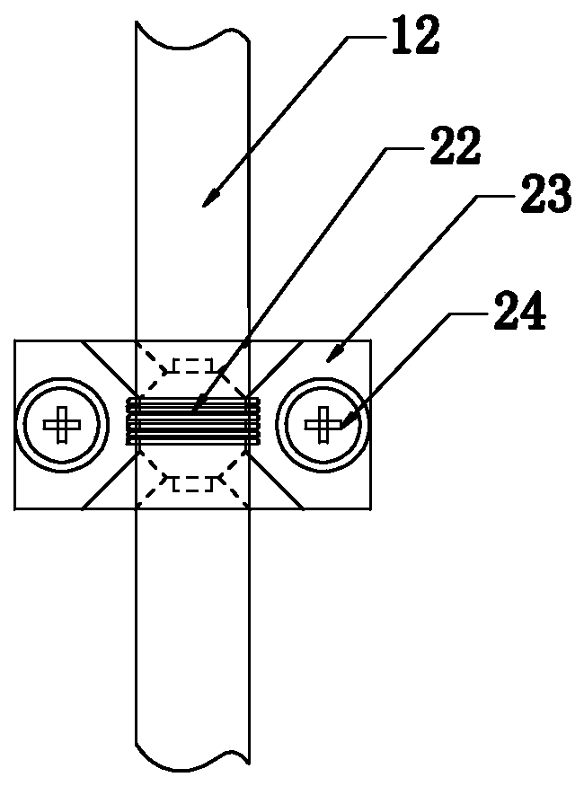
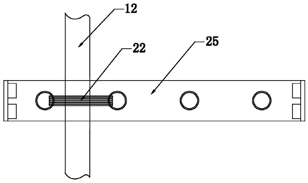
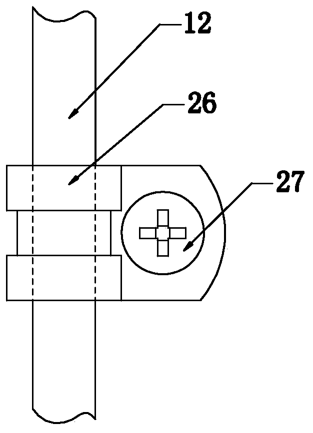
technical field [0001] The invention relates to a split-type clamping wire structure. Background technique [0002] The fixing of cables is often encountered in electronic equipment. Usually, silk ropes or cable ties are used to bind the cables to the reserved wiring devices such as wiring seats or wiring lines, or directly use buckles to wrap the cables. Then it is fixed on the casing by fasteners. [0003] For a schematic diagram of fixing cables with cable holders, see figure 1 , the wiring seat needs to be fastened to the mounting plate with two fasteners I, and the cables are bound to the wiring seat with silk ropes. This fixed structure has following defect: [0004] ①Two threaded holes need to be pre-drilled for the wiring seat. The spacing of the threaded holes is customized, and it is not easy to be compatible with other devices. [0005] ② There is a risk of off-line binding with brocade silk ropes, and it needs to be reinforced by applying glue, but the curing...

Claims


Application Information

Patent Timeline
Patent Type & Authority Applications(China)
IPC IPC(8): H02G3/04
CPCH02G3/0425H02G3/0456
Inventor 周超殷向阳黄锦源
Owner CHINA AVIATION OPTICAL-ELECTRICAL TECH CO LTD
Why Eureka
Try Eureka