Method for controlling vehicle systems in motor vehicles

A technology of a vehicle system, a motor vehicle, applied in the field of motor vehicles, capable of solving problems such as delayed reaction time

Pending Publication Date: 2020-03-10
HONDA MOTOR CO LTD
33 Cites 8 Cited by

AI-Extracted Technical Summary

Problems solved by technology

Drowsy or inattentive drive...

Method used

83 and 84 are schematic illustrations of an embodiment of a motor vehicle 100 navigating a curve on road 8300. 83 and 84 will be described with reference to FIGS. 1A , 1B, 2 and 3 . Referring to FIG. 83 , the driver 102 is awake and turning the steering wheel 134 . Also shown in FIG. 83 is the driver's desired route 8302 and the actual vehicle route 8304 . The driver's desired route can be determined from steering wheel information, yaw rate information, lateral g information, and other kinds of operational information. The driver desired route represents the ideal route of the vehicle given the steering input from the driver. However, due to changes in road traction and other conditions, the actual vehicle route may vary slightly from the driver's intended route. Referring to FIG. 84 , the response system 188 alters the operation of the electronic stability control system 202 when the driver 102 becomes drowsy. Specifically, the ESC system 202 is altered such that the actual vehicle route 3104 is closer to the driver's desired route 3006 . This helps minimize the discrepancy between the driver's desired route and the actual vehicle route when the driver is drowsy, which can help improve driving precision.
[0244] In some implementations, the motor vehicle 100 may include an anti-lock braking system 204 (also referred to as the ABS system 204). The ABS system 204 may include various components such as a speed sensor, a pump for applying pressure to the brake lines, a valve for removing pressure from the brake lines, and a controller. In some cases, a dedicated ABS controller can be used. In other cases, ECU 106 may act as an ABS controller. In other cases, the ABS system 204 may provide braking information (eg, brake pedal input and/or brake pedal input pressure/rate, etc.). Examples of anti-lock braking systems are known in the art. An example is disclosed in US Patent No. 6,908,161, filed November 18, 2003 by Ingaki et al., the entire contents of which are hereby incorporated by reference. Utilizing the ABS system 204 may help improve traction in the motor vehicle 100 by preventing the wheels from locking up during braking.
[0411] In some implementations, the vehicle monitoring system may include an anti-lock braking system 204 (also referred to as the ABS system 204). The ABS system 204 may include various components such as a speed sensor, a pump for applying pressure to the brake lines, a valve for removing pressure from the brake lines, and a controller. In some cases, a dedicated ABS controller can be used. In other cases, ECU 106 may act as an ABS controller. In other cases, the ABS system 204 may provide braking information (eg, brake pedal input and/or brake pedal input pressure/rate, etc.). Examples of anti-lock braking systems are known in the art. An example is disclosed in US Patent No. 6,908,161, filed November 18, 2003 by Ingaki et al., the entire contents of which are hereby incorporated by reference. Utilizing the ABS system 204 may help improve traction in the motor vehicle 100 by preventing the wheels from locking up during braking.
[0519] In step 2406, the response system 188 may determine whether the driver is distracted or otherwise impaired (eg, drowsy). If the driver is not distracted, the response system 188 may return to step 2402 to receive additional monitoring information. However, if the driver is distracted, the response system 188 may proceed to step 2408 . In step 2408, response system 188 may automatically alter control of one or more vehicle systems, including any of the vehicle systems discussed above. By automatically changing the control of one or more vehicle systems, the response system 188 may help avoid various dangerous situations that may be created by a drowsy and/or distracted driver.
[0528] In step 2418, the response system 188 may determine whether the response system 188 may determine whether the driver is drowsy or otherwise impaired (eg, sleepy). If the driver is not distracted, the response system 188 may return to step 2410 to receive additional monitoring information. However, if the driver is distracted, the response system 188 may proceed to step 2420 . In step 2420, response system 188 may automatically alter control of one or more vehicle systems, including any of the vehicle systems discussed above. By automatically changing the control of one or more vehicle systems, the response system 188 may help avoid various dangerous situations that may be created by a drowsy and/or distracted driver.
[0620] Additionally, one or more driver states may be mutually determined, combined and/or confirmed. By determining, combining and/or confirming one or more driver states, a reliable and robust driver monitoring system is provided. The driver monitoring system verifies driver status (e.g., to eliminate false positives), uses different types of monitoring information (e.g., multimodal input) to provide a combined driver status based on more than one driver status, and based on the combined driver status to change one or more vehicle systems. In this way, behavior and risk can be assessed in multiple modes and changes to vehicle s...

Abstract

Method for controlling vehicle systems in motor vehicles. A method for controlling vehicle systems includes receiving monitoring information from one or more monitoring systems and determining a plurality of driver states based on the monitoring information from the one or more monitoring systems. The method includes determining a combined driver state based on the plurality of driver states and modifying control of one or more vehicle systems based on the combined driver state.

Application Domain

Driver input parameters

Technology Topic

Driver/operatorControl engineering +4

Image

  • Method for controlling vehicle systems in motor vehicles
  • Method for controlling vehicle systems in motor vehicles
  • Method for controlling vehicle systems in motor vehicles

Examples

  • Experimental program(1)

Example Embodiment

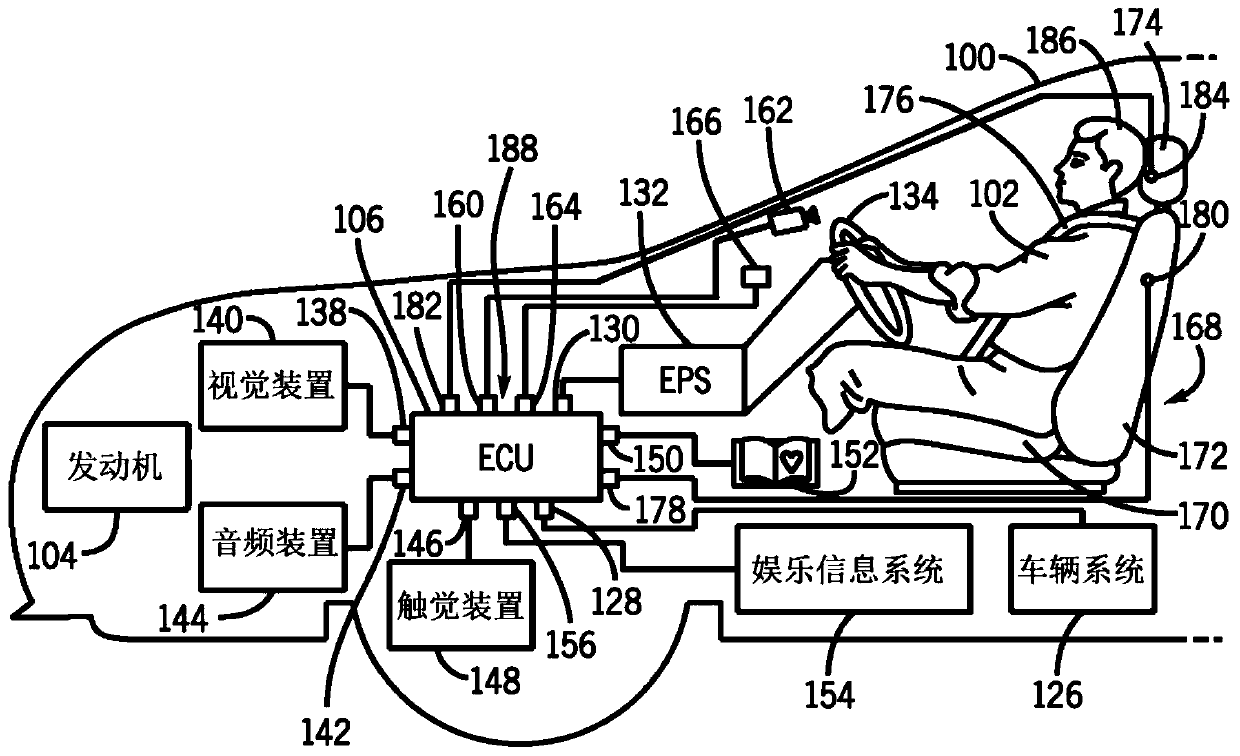
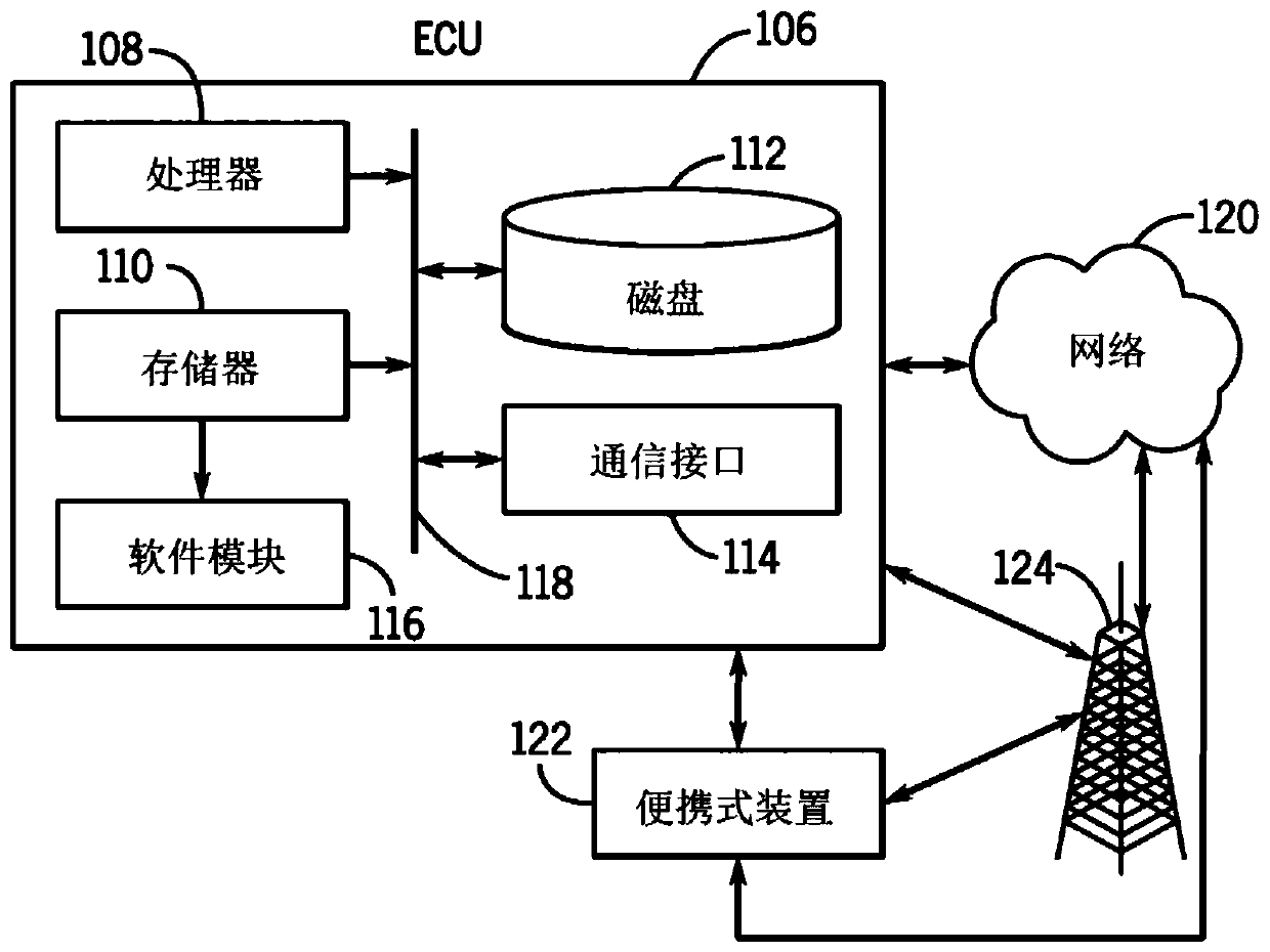
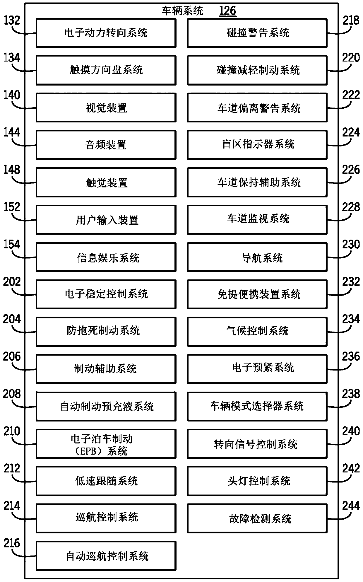
[0198] The following detailed description is intended to be exemplary and those of ordinary skill in the art will recognize that other embodiments and implementations are possible within the scope of the embodiments described herein. Exemplary embodiments are first described generally for a system overview including components of a motor vehicle, exemplary vehicle systems and sensors, and monitoring systems and sensors. After the general description, a system and method for evaluating driver status and operational response are proposed, including discussion and determination of driver status, determination of one or more driver status, determination of combined driver status, and confirmation of driver status. An exemplary implementation of detecting the driver state and exemplary operation response of the vehicle system based on the driver state and/or the combined driver state is also described. In addition, embodiments related to various levels of operational response from no control to semi-autonomous and fully autonomous responses based on the driver state are also discussed. For organizational structure purposes, the description is structured as paragraphs identified by headings, which are not intended to be limiting.
[0199] I. Overview
[0200] The specific embodiments and exemplary embodiments discussed herein describe systems and methods for realizing state monitoring of living organisms (eg, humans, animals, drivers, and passengers). Specifically, the specific embodiments and exemplary embodiments discussed herein refer to methods and systems with respect to motor vehicles. E.g, Figure 1A A schematic diagram showing an exemplary motor vehicle 100 and various components used to implement a system and method responsive to driver status. in Figure 1A In, the motor vehicle 100 is carrying the driver 102. In the systems and methods described herein, the motor vehicle 100 and the components of the motor vehicle 100 can provide status monitoring of the driver 102 and implement control based on the status monitoring. The term "driver" used in the present embodiment and claims may refer to any organism whose state (for example, driver state) is being monitored. In some cases, organisms are completing tasks that require condition monitoring. Examples of the term "driver" may include, but are not limited to, a driver who operates a vehicle, a vehicle occupant, a passenger in the vehicle, a patient, a security guard, an air traffic controller, an employee, a student, and the like. It should be understood that these systems and methods can also be implemented outside the vehicle. Therefore, the systems and methods described herein can be implemented in any location, situation, or device that requires or implements monitoring of the state of the organism. For example, in any location, situation, or device used to monitor people performing tasks that require a specific state. Examples include, but are not limited to, hospital locations, home locations, work locations, personal medical devices, portable devices, etc.
[0201] The "state" or "driver state" of a living body as used herein refers to the measurement of the state of the living body and/or the state of the surrounding environment (for example, a vehicle) of the living body. The driver state or alternatively the "biological state" may be alertness, alertness, drowsiness, inattention, distraction, nervousness, drunkenness, other common defective states, other emotional states, and/or general health states. Throughout the description, drowsiness and/or distraction will be used as example driver states to be evaluated. However, it is understood that any driver state can be determined and evaluated, including but not limited to drowsiness, concentration, distraction, alertness, unconsciousness, drunkenness, nervousness, emotional state and/or general health state, etc.
[0202] The driver state can be quantified as a driver state level, a driver state index, etc. In addition, one or more driver states may be used to determine a combined driver state level, a combined driver state index, etc. It is understood that the system and method for responding to the driver states discussed herein may include determining and/or evaluating one or more driver states based on information from the systems and sensors discussed herein. One or more driver states may be based on various types of information, for example, monitoring information, physiological information, behavior information, vehicle information, and so on.
[0203] As mentioned above, in addition to status monitoring, the systems and methods described herein can provide one or more responses by motor vehicle 100 based on driver status. Therefore, the assessments and adjustments discussed for the systems and methods in this article can be adapted to the driver's health, slow reaction time, distraction and/or alertness. For example, in situations where the driver may be drowsy and/or distracted, the motor vehicle may include a device for detecting the driver's drowsiness and/or distraction. In addition, because drowsiness and/or distraction can increase the likelihood of dangerous driving situations, motor vehicles may include equipment for automatically changing one or more vehicle systems to mitigate dangerous driving situations. Therefore, the systems and methods described herein can monitor and determine the state of a person and provide a response based on the state (e.g., control a motor vehicle and a component of a motor vehicle based on the state). Additionally, in some embodiments discussed herein, the systems and methods can monitor and determine the status of a person and provide automatic control of the motor vehicle and the components of the motor vehicle based on the driver status.
[0204] II. Overview of motor vehicle architecture
[0205] Now, referring to the accompanying drawings, the illustrations in the accompanying drawings are for the purpose of illustrating one or more exemplary embodiments, not for the purpose of limiting the embodiments, reference will be made to Figure 1A with Figure 1B An exemplary motor vehicle configuration for responding to driver status is described. For the sake of clarity, only some components of the motor vehicle are shown in the current embodiment. In addition, it will be understood that in other embodiments, some of the components may be optional. As mentioned above, Figure 1A A schematic diagram of an exemplary motor vehicle 100 carrying a driver 102 is shown, where various components of the motor vehicle are used to implement systems and methods for responding to the driver's state. The term "motor vehicle" as used throughout this embodiment and in the claims refers to any mobile vehicle capable of carrying one or more human passengers and powered by any form of energy. The term "motor vehicle" includes but is not limited to: cars, trucks, delivery trucks, minivans, SUVs, motorcycles, scooters, boats, personal ships and airplanes. In addition, the term "motor vehicle" may refer to autonomous vehicles and/or self-driving vehicles powered by any form of energy. An autonomous vehicle may or may not carry one or more organisms (e.g., humans, animals, etc.).
[0206] In general, the motor vehicle 100 can be propelled by any power source. In some embodiments, the motor vehicle 100 may be configured as a hybrid vehicle using two or more power sources. In other embodiments, motor vehicle 100 may use one or more engines. For example, in Figure 1A In this case, the motor vehicle 100 includes a single power source (engine 104). The number of cylinders in the engine 104 may vary. In some cases, the engine 104 may include six cylinders. In some cases, the engine 104 may be a three-cylinder, four-cylinder, or eight-cylinder engine. In other cases, the engine 104 may have any other number of cylinders.
[0207] The term "engine" used throughout this specification and claims refers to any device or machine capable of converting energy. In some cases, potential energy is converted into kinetic energy. For example, the energy conversion may include a situation where the chemical potential energy of the fuel or fuel cell is converted into rotational kinetic energy or the electric potential energy is converted into rotational kinetic energy. The engine may also include equipment for converting kinetic energy into potential energy. For example, some engines include a regenerative braking system that converts kinetic energy from the transmission system into potential energy. Engines may also include devices that convert solar or nuclear energy into another form of energy. Some examples of engines include, but are not limited to: internal combustion engines, electric motors, solar energy converters, turbines, nuclear power plants, and hybrid systems that combine two or more different types of energy conversion processes. It should be understood that in other embodiments, any other arrangement of components illustrated herein may be used to power the motor vehicle 100.
[0208] In general, motor vehicle 100 may include equipment for communicating with (in some cases, controlling them) various components associated with engine 104 and/or other systems of motor vehicle 100. In some embodiments, motor vehicle 100 may include a computer or similar device. In the current embodiment, the motor vehicle 100 may include an electronic control unit 106, referred to herein as an ECU 106. In one embodiment, the ECU 106 may be configured to communicate with and/or control various components of the motor vehicle 100.
[0209] Now refer to Figure 1B , Shows an exemplary block diagram of the ECU 106 in a connected vehicle environment according to one embodiment. In general, the ECU 106 may include a microcontroller, RAM, ROM, and software all used to monitor and monitor various components of the engine 104 and other components or systems of the motor vehicle 100. For example, the ECU 106 can receive signals from many sensors, devices, and systems located in the engine 104. The outputs of the various devices are sent to the ECU 106, where these device signals can be stored in an electronic memory such as RAM. Both the current signal and the electronically stored signal can be processed by a central processing unit (CPU) according to software stored in an electronic memory such as a ROM.
[0210] Such as Figure 1B As shown in the embodiment shown in, the ECU 106 includes a processor 108, a memory 110, a magnetic disk 112 and a communication interface 114. The processor 108 processes signals and performs general calculation and arithmetic functions. The signals processed by the processor may include digital signals, data signals, computer instructions, processor instructions, messages, bits, bit streams, or other means that can be received, sent, and/or detected. Generally, the processor may be a variety of processors, including multiple single-core processors and multi-core processors and coprocessors, and other multiple single-core and multi-core processors and coprocessor structures. In some embodiments, the processor may include various modules for performing various functions.
[0211] The memory 110 may include volatile memory and/or non-volatile memory. The non-volatile memory may include, for example, ROM (Read Only Memory), PROM (Programmable Read Only Memory), EPROM (Erasable PROM), and EEPROM (Electrically Erasable PROM). Volatile memory may include, for example, RAM (random access memory), synchronous RAM (SRAM), dynamic RAM (DRAM), synchronous DRAM (SDRAM), double data rate SDRAM (DDR SDRAM), and direct RAM bus RAM (DRRAM). The memory may store an operating system that controls or allocates resources of the ECU 106.
[0212] In addition, in some embodiments, the memory 110 may store and facilitate (e.g., by the processor 108) to execute various software modules 116. The modules described herein may include non-transitory computer-readable media that store instructions, instructions executed in a machine, hardware, firmware, software executed on a machine, and/or are all used to perform functions or Action and/or cause a combination of functions or actions from another module, method, and/or system. Modules may also include logic, microprocessors under software control, discrete logic circuits, analog circuits, digital circuits, programmed logic devices, memory devices containing instructions for execution, logic gates, combinations of gates, and/or other circuit components. Multiple modules can be combined into one module and a single module can be distributed across multiple modules. It is understood that in other embodiments, the software module 116 may be stored in the processor 108 and/or the disk 112.
[0213] The magnetic disk 112 may be, for example, a magnetic disk drive, a solid state disk drive, a floppy disk drive, a tape drive, a Zip drive, a flash memory card, and/or a memory stick. In addition, the magnetic disk may be a CD-ROM (compact disk ROM), a CD recordable drive (CD-R drive), a CD rewritable drive (CD-RW drive), and/or a digital video ROM device (DVD ROM). The magnetic disk may store an operating system that controls or allocates resources of the ECU 106.
[0214] The communication interface 114 provides software and hardware that facilitate data input and output between components of the ECU 106 and other components, networks, and data sources. The processor 108, the memory 110, the disk 112, and the communication interface 114 can all be connected via the data bus 118 in operation to facilitate computer communication. The data bus 118 refers to an interconnection structure that is operatively connected to other computer components inside the computer or connected between computers. The bus can transfer data between computer components. The bus may be a memory bus, a memory controller, a peripheral bus, an external bus, a crossbar switch, and/or a local bus. The bus can also be a vehicle bus. The vehicle bus uses protocols such as media-oriented system transmission (MOST), controller area network (CAN), local internet (LIN), etc. to connect components in the vehicle (for example, including vehicle systems and sensors) interconnection.
[0215] As mentioned above, the communication interface 114 can facilitate the connection environment of the motor vehicle 100. Therefore, the communication interface 114 facilitates the input and output of information with the ECU 106, other components of the motor vehicle 100, and other network devices by means of computer communication in a network environment. Computer communication may include (but is not limited to) network transmission, file transmission, data transmission, small application transmission, HTTP transmission, and the like. Computer communication can span, for example, logical connections, wireless systems (for example, IEEE 802.1 1), Ethernet systems (for example, IEEE 802.3), token ring systems (for example, IEEE 802.5), local area networks (LAN), wide area networks (WAN), point-to-point System, circuit switching system, packet switching system, etc.
[0216] For example, in Figure 1B , The communication interface 114 can facilitate a working connection for computer communication with the network 120. The connection can be implemented in various ways, for example, through a portable device 122, a cellular tower 124, an inter-vehicle ad-hoc network (not shown), an in-vehicle network (not shown), and other wired and wireless technologies. Therefore, the motor vehicle 100 can transmit data and receive data with external sources (for example, the network 120 and the portable device 122).
[0217] In addition to the communication interface 114, the ECU 106 may include Figure 1B The multiple ports shown in these ports facilitate the input and output of information and power. The term "port" used throughout the detailed description and claims refers to any interface or shared boundary between two wires. In some cases, ports can facilitate insertion and removal of wires. Examples of these types of ports include mechanical connectors. In other cases, the port is an interface that usually does not provide easy insertion or removal. Examples of these types of ports include soldering or electronic traces on circuit boards. In other cases, the port can facilitate a wireless connection.
[0218] The port facilitates the input and output of information with the ECU 106, other components of the motor vehicle 100, and other network devices via computer communication in a network environment. Computer communication may include (but is not limited to) network transmission, file transmission, data transmission, applet transmission, HTTP transmission, etc. Computer communication can span, for example, logical connections, wireless systems (for example, IEEE 802.1 1), Ethernet systems (for example, IEEE 802.3), token ring systems (for example, IEEE 802.5), local area networks (LAN), wide area networks (WAN), point-to-point Systems, circuit switching systems, packet switching systems, etc. In this article, the port and the data transmission between the port and different vehicle systems will be described in more detail.
[0219] As will be discussed in more detail throughout the specific embodiments, the ports and devices associated with the ECU 106 are optional. Some embodiments may include a given port or device, while other embodiments may exclude it. The detailed description discloses some of the possible ports and devices that may be used, however, it should be kept in mind that not every port or device need be used or every port or device need not be included in a given implementation. It is understood that the components of the motor vehicle 100 and ECU 106 discussed herein, as well as the components of other systems, hardware configurations, and software configurations discussed herein, may be combined, omitted, or organized into different configurations for various embodiments.
[0220] III. Systems and sensors
[0221] As mentioned above, one or more driver states can be evaluated based on various types of information. Different systems and sensors can be used to collect and/or analyze this information. In general, the sensors discussed herein sense and measure stimuli (e.g., signals, attributes) associated with motor vehicle 100, vehicle systems and/or components, the environment of motor vehicle 100, and/or organisms (e.g., driver 102) , Measurement, quality). The sensor can generate a data stream and/or signal representing the stimulus, analyze the signal and/or send the signal to another component, such as the ECU 106. In some embodiments, the sensor is part of the vehicle system and/or monitoring system that will be discussed herein.
[0222] The sensors discussed herein can include one sensor, more than one sensor, sensor groups, and can be part of a larger sensing system (e.g., monitoring system). It is to be understood that the sensors may have various configurations and may include different types of sensors, for example, current/potential sensors (e.g., proximity, inductance, capacitance, electrostatic), acoustic sensors, infrasound, acoustic and ultrasonic sensors, vibration sensors (e.g., Piezoelectric) vision sensors, imaging sensors, thermal sensors, temperature sensors, pressure sensors, photoelectric sensors, etc.
[0223] Now, exemplary vehicle systems, monitoring systems, sensors, and sensor analysis will be described in detail. It is understood that the vehicle systems, monitoring systems, sensors, and sensor analysis described herein are exemplary in nature and can be implemented by methods and systems for evaluating one or more driver states and controlling one or more vehicle systems Other systems and sensors.
[0224] A. Vehicle systems and sensors
[0225] Refer again Figure 1A The motor vehicle 100, the engine 104, and/or the ECU 106 may facilitate the transmission of information between the components of the motor vehicle 100 and/or may facilitate the control of the components of the motor vehicle 100. For example, motor vehicle 100 may include vehicle systems and vehicle sensors. Such as Figure 1A with figure 2 As shown in the embodiment, the motor vehicle 100 may include various systems, including a vehicle system 126. The vehicle system 126 may include, but is not limited to, any automatic or manual system that may be used to enhance measurement, driving, and/or safety.
[0226] Motor vehicle 100 and/or vehicle system 126 may include one or more vehicle sensors for sensing and measuring stimuli (eg, signals, attributes, measurements, quantities) associated with motor vehicle 100 and/or specific vehicle systems. ). In some embodiments, the ECU 106 may communicate via, for example, port 128 and obtain data representing stimuli from the vehicle system 126 and/or one or more vehicle sensors. The data may be vehicle information, and/or the ECU 106 may process the data into vehicle information and/or further process vehicle information. Therefore, the ECU 106 can transmit and obtain vehicles from the motor vehicle 100, the vehicle system 126 itself, one or more vehicle sensors associated with the vehicle system 126, or other vehicle sensors (for example, cameras, external radars, laser sensors, etc.) information.
[0227] Vehicle information includes Figure 1A Information related to the motor vehicle 100 and/or the vehicle system 126, the vehicle system 126 is included in figure 2 Those vehicle systems listed in. Specifically, the vehicle information may include vehicle and/or vehicle system conditions, states, conditions, behaviors, and information about the external environment of the vehicle (for example, other vehicles, pedestrians, objects, road conditions, weather conditions). Exemplary vehicle information includes (but is not limited to) acceleration information, speed information, steering information, lane departure information, blind spot monitoring information, braking information, collision warning information, navigation information, collision mitigation information, and cruise control information.
[0228] It is understood that the vehicle sensors may include (but are not limited to) vehicle system sensors of the vehicle system 126 and other vehicle sensors associated with the motor vehicle 100. For example, other vehicle sensors may include cameras installed inside or outside the vehicle, radar and laser sensors installed outside the vehicle, external cameras, radar and laser sensors (for example, on other vehicles in the inter-vehicle network, street cameras, surveillance cameras, etc.). camera). These sensors can be any type of sensors, for example, acoustic, electrical, environmental, optical, imaging, light, pressure, force, heat, temperature, proximity, etc.
[0229] In some embodiments, the ECU 106 may include devices for communicating with and/or controlling various systems and/or functions associated with the engine 104. In one embodiment, the ECU 106 may include a port 130 for receiving various types of steering information. In some cases, the ECU 106 may communicate with the electronic power steering system 32 (also referred to as EPS 132) through the port 130. EPS 132 may include various components and devices used to provide steering assistance. In some cases, for example, EPS 132 may include auxiliary motors and other devices for providing steering assistance to the driver. In addition, the EPS132 can be associated with various sensors, including torque sensors, steering angle sensors, and other types of sensors. Examples of electronic power steering systems are disclosed in U.S. Patent No. 7,497,471 filed by Kobayashi on February 27, 2006 and U.S. Patent No. 7,497,299 filed by Kobayashi on February 27, 2006, the entire contents of which are incorporated by reference In this article.
[0230] In some embodiments, the ECU 106 may include devices for communicating with and/or controlling various systems associated with the touch steering wheel. The ECU 106 may communicate with various systems associated with the touch steering wheel 134 via the port 130 and/or the EPS 132. In the embodiments described herein, the touch steering wheel 134 may also be referred to as a touch steering wheel system 134. The touch steering wheel system 134 may include various components and devices utilized to provide information about the contact and position of the driver's hand relative to the touch steering wheel 134. More specifically, the touch steering wheel 134 may include sensors (e.g., capacitive sensors, electrodes) installed in or on the touch steering wheel 134. The sensor is configured to measure the contact of the driver's hand with the touch steering wheel 134 and the contact position (for example, behavior information). It should be understood that, in some embodiments, the touch steering wheel 134 may provide contact information between other accessories of the driver (for example, wrists, elbows, shoulders, knees, arms, etc.) and the touch steering wheel 134.
[0231] In some embodiments, the sensors are located on the front and back of the touch steering wheel 134. Therefore, the sensor can determine whether the driver's hand is touching the front and/or back of the steering wheel 134 (eg, holding or wrapping the steering wheel). In other embodiments, the touch steering wheel system 134 can measure the force and/or pressure of a hand contact on the touch steering wheel 134. In other embodiments, the touch steering wheel system 134 can provide information about the hand on the touch steering wheel 134 and/or monitor its movement. For example, the touch steering wheel system 134 may provide information about the transition of hand movement or the transition of the number of hands touching the touch steering wheel 134 (for example, two hands on the touch steering wheel 134 change to one hand on the touch steering wheel 134; Putting only one hand on the touch steering wheel 134 is converted to putting two hands on the touch steering wheel 134). In some embodiments, the transition of the hand contact may set a time component, for example, a time period between two hands placed on the touch steering wheel 134 to one hand placed on the touch steering wheel 134. The information about the contact with the touch steering wheel 134 provided by the touch steering wheel system 134 may be referred to herein as hand contact information.
[0232] In some embodiments, the touch steering wheel system 134 may include sensors for measuring biological parameters (eg, physiological signals) of the driver of the vehicle. For example, the biological signal may include heart rate, skin capacitance, and/or skin temperature. The sensor may include, for example, one or more biological monitoring sensors 180. In another embodiment, touching the steering wheel 134 may provide information for activating the device and/or function of the vehicle system. For example, the sensor of the touch steering wheel system 134 may be used as a switch, where the contact and contact position of the driver's hand are associated with the device and/or the vehicle function that activates the vehicle. In other embodiments, the touch steering wheel system 134 may present information to the driver. For example, the touch steering wheel 134 may include one or more light elements and/or visual devices for providing information and/or instructions to the driver. The light element and/or visual device may provide warning signals and/or information related to one or more vehicle information. As an illustrative example, the warning signal may be associated with different visual cues (e.g., color, pattern). These visual cues can be a function of warning signals and/or driver status. An example of a touch steering wheel system is disclosed in US application serial number 14/744247 filed on June 19, 2015, the entire content of which is hereby incorporated by reference.
[0233] In some embodiments, the ECU 106 may include equipment for communicating with and/or controlling various visual devices. A visual device includes any device that can display information in a visual manner. These devices may include lights (such as dashboard lights, cab lights, etc.), visual indicators, video screens (such as navigation screens or touch screens), and any other visual devices. In one embodiment, the ECU 106 includes a port 138 for communicating with the vision device 140. In addition, in one embodiment, the vision device 140 may include a light element and/or a vision device integrated with other vehicle systems (for example, the touch steering wheel system 134).
[0234] In some embodiments, the ECU 106 may include equipment for communicating with and/or controlling various audio devices. Audio devices include any device that can provide information in an audible manner. These devices may include speakers and any systems associated with the speakers (such as radios, DVD players, BD players, CD players, cassette players, MP3 players, smart phones, portable devices, navigation systems, and audio information Any other system. In one embodiment, the ECU 106 may include a port 142 for communicating with the audio device 144. In addition, in some cases, the audio device 144 may be a speaker, while in other cases, the audio device 144 may This includes any system that can provide audio information to the speaker that can be heard by the driver.
[0235] In some embodiments, the ECU 106 may include equipment for communicating with and/or controlling various haptic devices. The term "haptic device" as used throughout this embodiment and in the claims refers to any device capable of delivering tactile stimuli to the driver or passenger. For example, haptic devices may include any device that vibrates or moves in other ways that can be felt by the driver. The haptic device can be provided in any part of the vehicle. In some cases, the haptic device may be located in the steering wheel (eg, touch steering wheel 134) to provide tactile feedback to the driver. In other cases, the haptic device may be located in a vehicle seat (e.g., vehicle seat 168) to provide tactile feedback or help the driver relax. In one embodiment, the ECU 106 may include a port 146 for communicating with and/or controlling the haptic device 148.
[0236] In some embodiments, the ECU 106 may include a device for receiving input from the user. For example, in some embodiments, the ECU 106 may include a port 150 for receiving information from the user input device 152. In some cases, the user input device 152 may include one or more buttons, switches, touch screens, touch pads, dials, pointers, or any other types of input devices. For example, in one embodiment, the user input device 152 may be a keyboard or a keypad. In another embodiment, the user input device 152 may be a touch screen. In one embodiment, the user input device 152 may be an ON/OFF switch. In another embodiment, the user input device 152 may include a touch steering wheel system 134. The user input device 152 may receive user input from the touch steering wheel system 134. In some cases, the user input device 152 may be used to turn on or turn off any driver status monitoring device associated with the vehicle or the driver. For example, in an embodiment where an optical sensor is used to detect driver status information, the user input device 152 may be used to turn this type of monitoring on or off. In embodiments utilizing multiple monitoring devices, the user input device 152 can be used to simultaneously turn on or off all the different types of monitoring associated with these monitoring devices. In other embodiments, the user input device 152 may be used to selectively turn some monitoring devices on or off, but not other monitoring devices. In other embodiments, the user input device 152 may be associated with the vehicle system 126 to selectively turn some vehicle systems 126 on or off.
[0237] In some embodiments, visual devices, audio devices, haptic devices, and/or input devices may be part of a larger infotainment system 154. in Figure 1A The ECU can receive information from the infotainment system 154 via the port 156. The infotainment system 154 may include a remote control unit (TCU) (not shown) to allow connection to the Internet to receive various media content. In one embodiment, the TCU may facilitate connection with cellular networks (e.g., 3G, 4G, LTE). For example, similar to the communication interface 114, the TCU may facilitate connection with the network 120, the portable device 122, and/or the cellular tower 124. In other embodiments, the TCU may include dedicated short-range communication (DSRC) that provides one-way or two-way short-range to medium-range wireless communication to the vehicle. Other systems and technologies may be used to allow connection to the Internet (eg, Internet 120) and data communication between the Internet, other vehicles, and other devices. For example, other vehicle communication systems (eg, networks with communication nodes between vehicles, other vehicles, roadside units, and other devices), inter-vehicle (V2V) networks that allow communication between vehicles, and other ad-hoc networks. To understand, Figure 1B The communication interface 114 shown in may facilitate communication between the aforementioned infotainment system 154 and other networks and devices.
[0238] In some embodiments, the ECU 106 may include ports for communicating with and/or controlling various engine components or systems. Examples of different engine components or systems include (but are not limited to): fuel injectors, spark plugs, electronic control valves, throttles, and other systems or components used for the operation of the engine 104. In addition, the ECU 106 may include additional ports for communicating with various other systems, sensors, or components of the motor vehicle 100. For example, in some cases, the ECU 106 may perform electrical communication with various sensors used to detect various operating parameters of the motor vehicle 100, including (but not limited to): vehicle speed, vehicle acceleration, accelerator pedal input , Accelerator pedal input pressure/rate, vehicle position, yaw rate, lateral g force, fuel level, fuel composition, various diagnostic parameters, and any other vehicle operating parameters and/or environmental parameters (such as ambient temperature, pressure, altitude Wait).
[0239] In one embodiment, the ECU 106 may include a port 160 for receiving information from one or more optical sensing devices such as the optical sensing device 162. The optical sensing device 162 may be any type of optical device, including digital cameras, video cameras, infrared sensors, laser sensors, and any other devices capable of detecting optical information. In one embodiment, the optical sensing device 162 may be a camera. In another embodiment, the optical sensing device 162 may be one or more cameras or optical tracking systems. In addition, in some cases, the ECU 106 may include a port 164 for communicating with the thermal sensing device 166. The thermal sensing device 166 may be configured to detect thermal information about the driver state and/or thermal information about the vehicle environment. In some cases, the optical sensing device 162 and the thermal sensing device 166 may be combined into a single sensor. As discussed in further detail herein, the optical sensing device 162 and the thermal sensing device 166 may be used to sense and detect physiological and/or behavioral information about the driver 102.
[0240] As discussed herein, the motor vehicle 100 may include one or more sensors for determining, acquiring, and/or obtaining information about the driver (more specifically, the status of the driver). in Figure 1A In the middle, the driver 102 sits in the vehicle seat 168. The vehicle seat 168 may include a lower support 170 and a seat back support 172 from which the seat back support 172 extends generally upward. In addition, the vehicle seat 168 may include a headrest 174 extending generally upward from the seat back support 172. In some embodiments, the vehicle seat 168 may also include a seat belt 176. in Figure 1A In this case, the safety belt 176 is generally shown as a shoulder belt portion, however, the safety belt 176 may also include a waist belt portion (not shown). It is understood that other configurations of vehicle seats can be realized.
[0241] Motor vehicle 100 may include, for example, one or more biomonitoring sensors disposed and/or located in vehicle seat 168. in Figure 1A The ECU 106 may include a port 178 for receiving information from the biomonitoring sensor 180 located in the seat back support 172. In other embodiments, the ECU 106 may include a port 182 for receiving information from the proximity sensor 184 located in the headrest 174. In some embodiments, the biological monitoring sensor 180 may be used to sense, receive, and monitor physiological information about the driver 102 (eg, heart rate information). In some embodiments, the proximity sensor 184 may be used to sense, receive, and monitor behavioral information about the driver 102 (eg, the distance between the headrest 174 and the head 186 of the driver 102). Here, the biological monitoring sensor 180 and the proximity sensor 184 for sensing and monitoring physiological and/or behavioral information about the driver 102 will be described in more detail.
[0242] In some embodiments, the ECU 106 may include devices for communicating with and/or controlling various other different vehicle systems. Vehicle systems include any automatic or manual system that can be used to enhance the driving experience and/or enhance safety. As mentioned above, in one embodiment, the ECU 106 may communicate with and/or control the vehicle system 126 via the port 128. For illustrative purposes, in the current embodiment, a single port for communication with the vehicle system 126 is shown. However, it should be understood that in some embodiments, more than one port may be used. For example, in some cases, separate ports may be used to communicate with the individual vehicle systems of the vehicle system 126. In addition, in embodiments where the ECU 106 includes a part of a vehicle system, the ECU 106 may include additional ports for communicating with and/or controlling various components or devices of the vehicle system. Additionally, in some embodiments discussed herein, the response system may receive information about the status of the driver 102 and automatically adjust the operation of the vehicle system 126. In these embodiments, Figure 1A with Figure 1B The various components shown in, alone or in combination, may be referred to herein as response system 188. In some cases, the response system 188 includes the ECU 106 and one or more sensors, components, devices, or systems discussed herein.
[0243] in figure 2 Examples of different vehicle systems 126 are shown in. figure 2 Also includes the above Figure 1A The described vehicle systems, specifically, EPS 132, touch steering wheel system 134, visual device 140, haptic device 148, user input device 152, and infotainment system 154. Should understand, figure 2 The system shown in is intended to be exemplary only, and in some cases, may include some other additional systems. In other cases, some of the systems may be optional and are not included in all implementations. Will refer to Figure 1A with Figure 1B Components to describe figure 2. Now refer to figure 2 The motor vehicle 100 may include an electronic stability control system 202 (also referred to as an ESC system 202). The ESC system 202 may include equipment for maintaining the stability of the motor vehicle 100. In some cases, the ESC system 202 may monitor the yaw rate and/or lateral g acceleration of the motor vehicle 100 to help improve traction and stability. The ESC system 202 may automatically activate one or more brakes to help improve traction. An example of an electronic stability control system is disclosed in US Patent No. 8,423,257 filed on March 17, 2010 by Ellis et al., the entire contents of which are hereby incorporated by reference. In one embodiment, the electronic stability control system may be a vehicle stability system.
[0244] In some embodiments, the motor vehicle 100 may include an anti-lock braking system 204 (also referred to as an ABS system 204). The ABS system 204 may include various different components (such as a speed sensor, a pump to apply pressure to the brake line, a valve to remove pressure from the brake line, and a controller). In some cases, a dedicated ABS controller can be used. In other cases, the ECU 106 may act as an ABS controller. In other cases, the ABS system 204 may provide braking information (eg, brake pedal input and/or brake pedal input pressure/rate, etc.). Examples of anti-lock braking systems are known in the art. An example is disclosed in US Patent No. 6,908,161 filed on November 18, 2003 by Ingaki et al., the entire content of which is hereby incorporated by reference. Utilizing the ABS system 204 can help improve traction in the motor vehicle 100 by preventing the wheels from locking during braking.
[0245] The motor vehicle 100 may include a brake assist system 206. The brake assist system 206 may be any system that helps reduce the force required by the driver to depress the brake pedal. In some cases, the brake assist system 226 may be activated for older drivers or any other drivers who may need to assist braking. Examples of brake assist systems can be found in U.S. Patent No. 6,309,029 filed by Wakabayashi et al. on November 17, 1999, the entire contents of which are hereby incorporated by reference.
[0246] In some embodiments, the motor vehicle 100 may include an automatic brake priming system 208 (also referred to as an ABP system 208). The ABP system 208 includes a device for pre-filling one or more brake lines with brake fluid before a collision. This can help increase the reaction time of the braking system when the driver depresses the brake pedal. Examples of automatic brake priming systems are known in the art. An example is disclosed in U.S. Patent No. 7,806,486 filed by Bitz on May 24, 2007, the entire content of which is hereby incorporated by reference.
[0247] In some embodiments, the motor vehicle 100 may include an electronic parking brake (EPB) system 210. The EPB system 210 includes equipment for keeping the motor vehicle 100 stationary on slopes and flat roads. Specifically, the motor vehicle 100 may include an electronic parking brake switch (eg, a button) that can be activated by the driver 102. When activated, the EPB system 210 controls the braking system discussed above to apply brakes to one or more wheels of the motor vehicle 100. To release the brake, the driver can engage the electronic parking brake switch and/or depress the accelerator pedal. In addition, the EPB system 210 or other braking systems may include an automatic brake retention control feature that maintains the brake retention when the vehicle is stopped or even after the brake pedal is released. Therefore, when the vehicle comes to a complete stop, the brake remains engaged and continues to hold the brake until the accelerator pedal is engaged. In some embodiments, a button can be used to manually engage the automatic brake retention control feature. In other embodiments, the automatic brake keep control feature is automatically engaged.
[0248] As mentioned above, the motor vehicle 100 includes equipment for communicating with and/or controlling various systems and/or functions associated with the engine 104. In one embodiment, the engine 104 includes an idling stop function, which can be based on, for example, the engine 104 (for example, automatic transmission), the anti-lock braking system 204, the brake assist system 205, and the automatic braking by the ECU 106 and/or the engine 104. The information of the priming system 208 and/or the EPB system 210 controls the idling stop function. Specifically, the idling stop function includes equipment for automatically stopping and restarting the engine 104 to help maximize fuel combustion efficiency according to the environment and vehicle conditions. For example, the ECU 106 may activate the idling stop function based on gear information from the engine 104 (eg, automatically transmitted) and brake pedal position information from the aforementioned braking system. Therefore, when the vehicle is stopped in the forward gear (D) gear position and the brake pedal is depressed, the ECU 106 controls the engine to turn off. When the brake pedal is subsequently released, the ECU 106 controls the engine to restart (for example, turn it on) and the vehicle can start to move. In some embodiments, when the idling stop function is activated, the ECU 106 may control the visual device 140 to provide an idling stop indicator to the driver. For example, the visual device 140 on the dashboard of the motor vehicle 100 can be controlled to display an idling stop indicator. Based on other vehicle conditions (for example, the seat belt is fastened, the vehicle is parked on a steep slope), in some cases, the activation of the idling stop function may be disabled. In addition, the idle stop function may be manually controlled by the driver 102 using, for example, an idle stop switch located in the motor vehicle 100.
[0249] In some embodiments, the motor vehicle 100 may include a low-speed following system 212 (also referred to as an LSF system 212). The LSF system 212 includes a device for automatically following the preceding vehicle according to a set distance or distance range. This can reduce the need for the driver to keep pressing and depressing the accelerator pedal in slow traffic situations. The LSF system 212 may include components for monitoring the relative position of the preceding vehicle (for example, using a remote sensing device such as lidar or radar). In some cases, the LSF system 212 may include equipment for communicating with any preceding vehicle to determine the GPS location and/or speed of the vehicle. Examples of low-speed following systems are known in the art. An example is disclosed in U.S. Patent No. 7,337,056 filed by Arai on March 23, 2005, the entire content of which is hereby incorporated by reference. Another example is disclosed in U.S. Patent No. 6,292,737 filed by Higashimata et al. on May 19, 2000, the entire content of which is hereby disclosed by reference.
[0250] The motor vehicle 100 may include a cruise control system 214. Cruise control systems are well known in the art and allow users to set the cruise speed automatically maintained by the vehicle control system. For example, when traveling on a highway, the driver can set the cruising speed to 55mph. The cruise control system 214 may automatically maintain the vehicle speed at approximately 55 mph until the driver depresses the brake pedal or otherwise disables the cruise function.
[0251] The motor vehicle 100 may include an automatic cruise control system 216 (also referred to as an ACC system 216). In some cases, the ACC system 216 may include a device for automatically controlling the vehicle to maintain a predetermined following distance behind the preceding vehicle or to prevent the vehicle from getting closer to the preceding vehicle than the predetermined distance. The ACC system 216 may include components for monitoring the relative position of the preceding vehicle (for example, using a remote sensing device such as lidar or radar). In some cases, the ACC system 216 may include equipment for communicating with any preceding vehicle to determine the GPS location and/or speed of the vehicle. An example of an automatic cruise control system is disclosed in US Patent No. 7,280,903 filed August 31, 2005 by Arai et al., the entire contents of which are hereby incorporated by reference.
[0252] The motor vehicle 100 may include a collision warning system 218. In some cases, the collision warning system 218 may include equipment for warning the driver of any potential collision threats with one or more vehicles, objects, and/or pedestrians. For example, the collision warning system may warn the driver when the motor vehicle 100 is approaching an intersection while another vehicle is passing the same intersection. Examples of collision warning systems are disclosed in U.S. Patent No. 8,558,718 filed by Mochizuki on September 20, 2010, and U.S. Patent No. 8,587,418 filed by Mochizuki et al. on July 28, 2010, the entire contents of which are hereby incorporated by reference Incorporated. In one embodiment, the collision warning system 218 may be a forward collision warning system, including warnings for vehicles and/or pedestrians. In another embodiment, the collision warning system 218 may be a cross-traffic monitoring system, using backup cameras or rear sensors to determine whether a pedestrian or another vehicle is behind the vehicle.
[0253] Motor vehicle 100 may include a collision mitigation braking system 220 (also referred to as CMBS system 220). The CMBS 220 may include equipment for monitoring vehicle operating conditions (including target vehicles, objects, and pedestrians in the vehicle environment) and automatically applying various stages of warning and/or control to mitigate collisions. For example, in some cases, the CMBS 220 may use radar or other types of remote sensing devices to monitor the preceding vehicle. If the motor vehicle 100 is too close to the preceding vehicle, the CMBS 220 may enter the first warning stage. During the first warning phase, a visual and/or audible warning may be provided to warn the driver. If the motor vehicle 100 continues to get closer to the preceding vehicle, the CMBS 220 may enter the second warning stage. During the second warning phase, the CMBS 220 may apply automatic seat belt pretensioning. In some cases, the visual and/or audible warning can continue throughout the second warning phase. In addition, in some cases, during the second phase, automatic braking can also be activated to help reduce vehicle speed. In some cases, the third stage of operation for the CMBS 220 may involve automatically braking the vehicle and tightening the seat belt in the most likely collision situation. An example of this system is disclosed in US Patent No. 6,607,255 filed by Bond et al. on January 17, 2002, the entire contents of which are hereby incorporated by reference. The term "collision mitigation braking system" as used throughout this embodiment and in the claims can refer to any system that can sense a potential collision threat and provide various types of warning responses and automatically brake in response to a potential collision .
[0254] Motor vehicle 100 may include a lane departure warning system 222 (also referred to as LDW system 222). The LDW system 222 can determine when the driver has deviated from the lane and provide a warning signal to warn the driver. An example of a lane departure warning system can be found in US Patent No. 8,063,754 filed by Tanida et al. on December 17, 2007, the entire content of which is incorporated by reference.
[0255] Motor vehicle 100 may include blind spot indicator system 224 (also referred to as BSI system 224). The blind spot indicator system 224 may include equipment to help monitor the driver's blind spot. In some cases, the blind spot indicator system 224 may include a device for warning the driver whether the vehicle is in the blind spot. In other cases, the blind spot indicator system 224 may include a device for warning the driver whether pedestrians or other objects are located in the blind spot. Any known system for detecting objects traveling around a vehicle can be used.
[0256] In some embodiments, the motor vehicle 100 may include a lane keeping assist system 226 (also referred to as the LKAS system 226). The lane keeping assist system 226 may include equipment for helping the driver stay in the current lane. In some cases, the lane keeping assist system 226 may warn the driver if the motor vehicle 100 has accidentally drifted into another lane. In addition, in some cases, the lane keeping assist system 226 may provide assist control to keep the vehicle in a predetermined lane. For example, the lane keeping assist system 226 may control the electronic power steering system 132 by applying a certain amount of reverse steering force to keep the vehicle in a predetermined lane. In another embodiment, for example, the lane keeping assist system 226 in an automatic control mode may automatically control the electronic power steering system 132 to keep the vehicle in the predetermined lane based on identifying and monitoring the lane markings of the predetermined lane. An example of a lane keeping assist system is disclosed in US Patent No. 6,092,619 filed on May 7, 1997 by Nishikawa et al., the entire contents of which are hereby incorporated by reference.
[0257] In some embodiments, the motor vehicle 100 may include a lane monitoring system 228. In some embodiments, the lane monitoring system 228 may be combined or integrated with the blind spot indicator system 224 and/or the lane keeping assist system 226. The lane monitoring system 228 includes equipment for monitoring and detecting vehicle status and elements in the vehicle environment (for example, pedestrians, objects, other vehicles, cross traffic, etc.). Upon detecting the element, the lane monitoring system 228 may warn the driver and/or cooperate with the lane keeping assist system 226 to assist in maintaining vehicle control to avoid potential collisions and/or dangerous situations. The lane keeping assist system 226 and/or the lane monitoring system 228 may include sensors and/or optical devices (e.g., cameras) located in various areas (e.g., front, rear, side, roof) of the vehicle. These sensors and/or optical devices provide a wider view of the road and/or vehicle environment. In some embodiments, the lane monitoring system 228 may capture images of the rear area of ​​the vehicle and the blind area of ​​the vehicle outside the field of view of the side mirror adjacent to the rear area of ​​the vehicle, compress the image and The image is displayed to the driver. An example of a lane monitoring system is disclosed in U.S. Publication No. 2013/0038735 filed on February 16, 2011 by Nishiguichi et al., the entire content of which is incorporated by reference. It should be understood that after detecting the state of the vehicle, the lane monitoring system 228 can be used with other vehicle systems (eg, electronic stability control system 202, brake assist system 206, collision warning system 218, collision mitigation braking system 220, blind spot indicator system 224 Etc.) Provide warnings or driver assistance.
[0258] In some embodiments, the motor vehicle 100 may include a navigation system 230. The navigation system 230 may be any system capable of receiving, transmitting, and/or processing navigation information. The term "navigation information" refers to any information that can be used to assist in determining a location or provide directions to a location. Some examples of navigation information include: street address, street name, street or address number, apartment or suite number, intersection information, points of interest, parking lot, any political or geographic divisions, including: towns, towns, provinces, districts, City, state, administrative district, ZIP or postal code, and country. Navigation information can also include commercial information, including: store and restaurant names, commercial areas, shopping centers, and parking facilities. In some cases, the navigation system may be integrated into a motor vehicle, for example, as part of the infotainment system 154. The navigation information may also include other information about the traffic mode, the characteristics of the road, and other information about the road on which the motor vehicle is currently driving or the road on which the current route will be driven. In other cases, the navigation system may be a portable stand-alone navigation system, or may be part of a portable device (eg, portable device 122).
[0259] As mentioned above, in some embodiments, the visual device 140, the audio device 144, the haptic device 148, and/or the user input device 152 may be part of a larger infotainment system 154. In other embodiments, a larger infotainment system 154 may facilitate the connection of mobile phones and/or portable devices to the vehicle to allow, for example, content from the mobile device to be played to the infotainment system. Therefore, in one embodiment, the vehicle may include a hands-free portable device (eg, telephone) system 232. The hands-free portable device system 232 may include, for example, a telephone device integrated with an infotainment system, a microphone (for example, an audio device) installed in a vehicle. In one embodiment, the hands-free portable device system 232 may include a portable device 122 (e.g., a mobile phone, a smart phone, a tablet with phone capabilities). The telephone device is configured to use a portable device, a microphone, and a vehicle audio system to provide in-vehicle telephone functions and/or to provide content from a portable device in the vehicle. In some embodiments, the telephone device is omitted because the portable device can provide telephone functions. This allows vehicle occupants to implement the functions of a portable device through the infotainment system without physical interaction with the portable device.
[0260] The motor vehicle 100 may include a climate control system 234. The climate control system 234 may be any type of system used to control the temperature or other environmental conditions in the motor vehicle 100. In some cases, the climate control system 234 may include heating, ventilation, and air conditioning systems and electronic controllers for operating the HVAC system. In some embodiments, the climate control system 234 may include a separate dedicated controller. In other embodiments, the ECU 106 may act as a controller for the climate control system 234. Any kind of climate control system known in the art can be used.
[0261] The motor vehicle 100 may include an electronic pretensioning system 236 (also referred to as an EPT system 236). The EPT system 236 may be used with a seat belt for the motor vehicle 100 (eg, seat belt 176). The EPT system 236 may include equipment for automatically tightening, or tightening the seat belt 176. In some cases, the EPT system 236 can automatically pre-tension the seat belt before a collision. An example of an electronic pretensioning system is disclosed in US Patent No. 6,164,700 filed by Masuda et al. on April 20, 1999, the entire content of which is incorporated by reference.
[0262] The motor vehicle 100 may include a vehicle mode selector system 238 that changes the driving performance according to preset parameters related to the selected mode. These modes may include (but are not limited to) normal, economy, sports, sports+ (plus), automatic, terrain/condition specific modes (eg, snow, mud, off-road, steep slope). For example, in the economy mode, the ECU 106 may control the engine 104 (or a vehicle system related to the engine 104) to provide a more consistent engine speed, thereby improving fuel combustion efficiency. The ECU 106 may also control other vehicle systems to reduce the load on the engine 104, such as changing the climate control system 234. In the sport mode, the ECU 106 may control the EPS 132 and/or the ESC system 202 to increase steering feel and feedback. In terrain/condition specific modes (for example, snow, mud, sand, off-road, steep slopes), the ECU 106 can control various vehicle systems to provide handling and safety features that contribute to specific terrain and conditions. In the automatic mode, the ECU 106 can control various vehicle systems to provide full (e.g., autonomous) or partial automatic control of the vehicle. It is to be understood that the above-mentioned modes and mode features are exemplary in nature and other modes and features can be implemented. In addition, it is understood that more than one mode can be implemented simultaneously or substantially simultaneously.
[0263] The motor vehicle 100 may include a turn signal control system 240 for controlling turn signals (eg, direction indicators) and braking signals. For example, the turn signal control system 240 may control turn signal indicator lights (for example, installed on the front, rear, left, and right corners of the vehicle, the side of the vehicle, and the outside mirror). The turn signal control system 240 may control (for example, turn on/off) the turn signal indicator light when receiving a turn signal input from the driver (for example, via the user input device 152, a turn signal actuator, etc.). In other embodiments, the turn signal control system 240 may control the characteristics and/or visual cues of the turn signal indicator light, for example, brightness, color, light pattern, mode, etc. Feature and/or visual cue control may be based on input received from the driver or may be automatic control based on input from another vehicle system and/or driver status. For example, the turn signal control system 240 may control turn signal indicator lights based on an emergency event (eg, receiving a signal from a collision warning system) to provide warnings to other vehicles and/or provide information about occupants in the vehicle. In addition, the turn signal control system 240 may control the actuation signal (for example, a brake indicator light installed at the rear of the vehicle) alone or in combination with the brake system discussed herein. The turn signal control system 240 may also control the characteristics of the actuation signal and/or visual cues, similar to the turn signal indicator lights described above.
[0264] The motor vehicle 100 may include a headlight control system 242 for controlling headlights and/or floodlights installed on the vehicle (for example, at the left and right front corners of the vehicle). The headlight control system 242 may control (eg, turn on/off, adjust) the headlights when receiving input from the driver. In other embodiments, the headlight control system 242 may automatically and dynamically control (eg, turn on/off, adjust) the headlights based on information from one or more of the vehicle systems. For example, the headlight control system 242 may activate the headlights and/or adjust the characteristics of the headlights based on environmental/road conditions (eg, external brightness, weather), time of day, and/or the like. It is understood that the turn signal control system 240 and the headlight control system 242 may be part of a larger vehicle lighting control system.
[0265] The motor vehicle 100 may include a fault detection system 244 that detects a fault in one or more of the vehicle systems 126. More specifically, the fault detection system 244 receives information from the vehicle system and performs a fail-safe function (for example, system shutdown) or a non-fail safe function (for example, system control) based on the information and the degree of failure. In operation, the fault detection system 244 monitors and/or receives signals from one or more vehicle systems 126. These signals are analyzed and compared with predetermined faults and control levels, which are associated with vehicle systems. Once the fault detection system 244 detects that the signal meets a predetermined level, the fault detection system 244 starts to control and/or shut down one or more vehicle systems. It is understood that one or more of the vehicle systems 126 may implement an independent fault detection system. In some embodiments, the fault detection system 244 may be integrated with the on-board diagnostic system of the motor vehicle 100. Additionally, in some embodiments, the fault detection system 244 may determine the fault of a vehicle system based on a comparison of information from more than one vehicle system. For example, the fault detection system 244 can compare the information from the touch steering wheel system 134 and the electronic power steering system 132 indicating the contact of hands and/or appendages to determine the fault of the touch sensor, as submitted on June 8, 2015 It is described in U.S. Application Serial No. 14/733836, which is incorporated herein by reference.
[0266] It is understood that the vehicle system 126 may include any other types of devices, components, or systems used with the vehicle. In addition, each of these vehicle systems may be a standalone system or may be integrated with the ECU 106. For example, in some cases, the ECU 106 may work as a controller for various components of one or more vehicle systems. In other cases, some systems may include a separate dedicated controller that communicates with the ECU 106 through one or more ports.
[0267] In addition, it should be understood that the vehicle system 126, other vehicle systems discussed herein, sensors, and monitoring systems (eg, physiological monitoring systems discussed in Part III(B)(1), Part III(B)(2) discussed The behavior monitoring system, the vehicle monitoring system discussed in Part III(B)(3), and the recognition system and sensors discussed in Part III(B)(4)) may be vehicle systems and/or include vehicle systems and are carried out in this article discuss. Additionally, it is to be understood that any combination of vehicle systems and sensors, physiological monitoring systems, behavior monitoring systems, vehicle monitoring systems, and recognition systems can be implemented to determine and/or evaluate one or more driver states discussed herein.
[0268] B. Monitoring system and sensors
[0269] In general, the monitoring system used herein may include any system configured to provide monitoring information related to motor vehicle 100, driver 102 of motor vehicle 100, and/or vehicle system 126. More specifically, these monitoring systems determine, obtain, and/or obtain information about the driver, for example, information about the state of the driver or information for evaluating the state of the driver. In some embodiments, the ECU 106 may communicate via one or more ports and obtain monitoring information from, for example, a monitoring system and/or one or more monitoring system sensors.
[0270] The monitoring system may include (but is not limited to) optical devices, thermal devices, autonomous monitoring devices, and any other types of devices, sensors, or systems. More specifically, the monitoring system may include systems and sensors such as a vehicle monitoring system, a physiological monitoring system, a behavior monitoring system, and related sensors. In addition, the monitoring information may include physiological information, behavior information, and vehicle information.
[0271] It should be understood that in some embodiments, the vehicle system and the monitoring system may be used alone or in combination to receive monitoring information. In some cases, monitoring information may be received directly from the vehicle system, rather than from a system or component designed to monitor the status of the driver. In some cases, monitoring information can be received from both the monitoring system and the vehicle system. Therefore, one or more monitoring systems may include one or more vehicle systems ( Figure 1A , Figure 1B , figure 2 ) And/or one or more monitoring systems ( image 3 ). In addition, as mentioned above, as described in more detail below, it may include Figure 1A , Figure 1B , figure 2 with image 3 Other additional vehicle systems and/or monitoring systems shown in.
[0272] It should be understood that each of the monitoring systems discussed herein may be associated with one or more sensors or other devices. In some cases, the sensor may be provided in one or more parts of the motor vehicle 100. For example, these sensors may be integrated into the dashboard, seat (for example, seat 168), seat belt (for example, seat belt 176), door, instrument panel, steering wheel (for example, touch steering wheel system 134), center console, car Roof or any other part of the motor vehicle 100. However, in other cases, these sensors may be portable sensors worn by the driver, integrated into a portable device (for example, portable device 122) carried by the driver, integrated into an article of clothing worn by the driver, or Integrate into the driver's body (e.g., implant). Below, specific types of sensors and sensor arrangements will be discussed in more detail.
[0273] Hereinafter, an exemplary monitoring system and other exemplary sensors, sensing devices, and sensor analysis (for example, analysis and processing of data measured by sensors) are described in detail. It is understood that one or more components/functions of each of the systems and methods discussed herein may be in motor vehicle 100, components of motor vehicle 100, vehicle system 126, Figure 1A , Figure 1B , figure 2 with image 3 Monitoring system and relative to Figure 1A , Figure 1B , figure 2 with image 3 Implemented within or in conjunction with the described systems and methods. The exemplary monitoring systems, sensors, sensing devices, and sensor analysis described below generally detect and provide monitoring information, and may determine one or more driver states of the driver of the motor vehicle 100. One or more driver states may be utilized by the methods and systems described with respect to other figures herein to control and/or change one or more vehicle systems. Exemplary monitoring systems, sensors, sensing devices, and sensor analysis are non-limiting, and for other exemplary embodiments (including relative to Figure 1A , Figure 1B , figure 2 with image 3 Exemplary embodiments), the components and/or functions of the construction and method may be rearranged and/or omitted.
[0274] 1. Physiological monitoring system and sensors
[0275] Generally, physiological monitoring systems and sensors include (but are not limited to) any automatic or manual systems and sensors that monitor and provide physiological information related to the driver of a motor vehicle (eg, related to the driver's status). The physiological monitoring system may include methods for sensing and measuring stimuli (eg, signals, attributes, measurements, and/or quantities) associated with the driver of the motor vehicle 100. In some embodiments, the ECU 106 may transmit and obtain a data stream representing stimuli from the physiological monitoring system, for example, from a port. In other words, the ECU 106 can transmit and obtain physiological information from the physiological monitoring system of the motor vehicle 100.
[0276] Physiological information includes information about the human body (for example, the driver) derived from the essence. In other words, physiological information can be measured by medical devices and quantify the internal characteristics of the human body. Physiological information is usually not what the human eye can observe from the outside. However, in some cases, physiological information can be observed through the optical device, for example, the heart rate measured by the optical device. Physiological information may include, but is not limited to, heart rate, blood pressure, oxygen content, blood alcohol content (BAC), respiration rate, perspiration rate, skin conductivity, brain wave activity, digestion information, saliva secretion information, etc. Physiological information can also include information about the autonomic nervous system of the human body derived from the essence.
[0277] Essential derivation includes physiological sensors that directly measure the internal characteristics of the human body. For example, heart rate sensor, blood pressure sensor, oxygen content sensor, blood alcohol content (BAC) sensor, EEG sensor, FNIRS sensor, FMRI sensor, biological monitoring sensor, etc. It is to be understood that the physiological sensor may be a contact sensor and/or a contactless sensor, and may include current/potential sensors (e.g., proximity, inductance, capacitance, electrostatic), acoustic sensors, infrasound, acoustic and ultrasonic sensors, vibration sensors (e.g., Piezoelectric), optical sensors, imaging sensors, thermal sensors, temperature sensors, pressure sensors, photoelectric sensors, etc.
[0278] In some embodiments, the ECU 106 may include a device for receiving information about the physiological state of the driver. In one embodiment, the ECU 106 may receive physiological information related to the driver's autonomic nervous system (or visceral nervous system). As mentioned above, in one embodiment, the ECU 106 may include a port 178 for receiving physiological information about the driver's state from the biological monitoring sensor 180. Examples of different physiological information about the driver that can be received from the biomonitoring sensor 180 include (but are not limited to): heart information such as heart rate, blood pressure, blood flow rate, oxygen content, blood alcohol content (BAC), etc., such as brain electricity Image (EEG) measurement, functional near-infrared spectrum (fNIRS), functional magnetic resonance imaging (fMRI) and other brain information, digestion information, breathing rate information, salivation information, perspiration information, pupil dilation information, and interaction with the driver Other types of information related to the autonomic nervous system or other biological systems.
[0279] In general, the biomonitoring sensor can be provided in any part of the motor vehicle. In some cases, the bio-monitoring sensor can be located close to the driver. For example, in Figure 1A In one embodiment shown in, the biological monitoring sensor 180 is located in or on the driver's seat 168 (more specifically, the seat back support 172). However, in other embodiments, the biological monitoring sensor 180 may be located in any other part of the motor vehicle 100, including but not limited to: steering wheel (e.g., touch steering wheel 134), headrest (e.g., headrest 174), seat belt ( For example, seat belts 176), armrests, dashboards, rearview mirrors, and any other locations. In addition, in some cases, the bio-monitoring sensor 180 may be a portable sensor that is worn by the driver and associated with a portable device located close to the driver (such as a smart phone (eg, portable device 122) or the like), It is associated with the article of clothing worn by the driver or integrated with the driver's body (for example, an implant). In addition, it is to be understood that the systems and methods described herein may include one or more biomonitoring sensors. Exemplary types and locations of sensors will be discussed in more detail herein.
[0280] In some embodiments, the ECU 106 may include a device for receiving various types of optical information about the physiological state of the driver. As mentioned above, in one embodiment, the ECU 106 may include a port 160 for receiving information from one or more optical sensing devices such as the optical sensing device 162. The optical sensing device 162 may be any kind of optical device, including digital cameras, video cameras, infrared sensors, laser sensors, and any other devices capable of detecting optical information. In one embodiment, the optical sensing device 162 may be a camera. In another embodiment, the optical sensing device 162 may be one or more cameras or optical tracking systems. In addition, in some cases, the ECU 106 may include a port 164 for communicating with the thermal sensing device 166. The thermal sensing device 166 may be configured to detect thermal information about the physiological state of the driver. In some cases, the optical sensing device 162 and the thermal sensing device 166 may be combined into a single sensor.
[0281] Optical and thermal sensing devices can be used to monitor physiological information from image data, such as heart rate, pulse, blood flow rate, skin color, pupil dilation, breathing rate, oxygen content, blood alcohol content (BAC), etc. For example, the heart rate and cardiac pulse (cardiacpulse) can be extracted and calculated by remote and non-contact devices using digital color video recordings of human faces, as described by Poh et al. in "Advancements in Noncontact, Multiparameter Physiological Measurements Using a Webcam" (Biomedical Engineering, IEEE Transactions on,vol.58,no.1,pp.7,11,Jan.201 1) and "Non-contact, Automated Cardiac PulseMeasurements Using Video Imaging and Blind Source Separation" (Optics Express18(2010):10762) Proposed in.
[0282] In addition, image and video zoom can be used to visualize the blood flow and small movements of the driver's face. This information can be used to extract blood flow rate, pulse rate, and skin color information, as described by Wu et al. in "Eulerian Video Magnification for Revealing Subtle Changes in the World" (ACM Trans.Graph.31, 4, Article 65 (July 2012), 8 Page). It is understood that information from optical and thermal sensing devices (such as oxygen content and blood alcohol content) can be used to extract other types of physiological information.
[0283] Refer now image 3 , A diagram showing various embodiments of monitoring systems 300 and sensors that may be associated with the motor vehicle 100. The monitoring system 300 determines, obtains, and/or obtains information about the driver (more specifically, the status of the driver). In some cases, the surveillance system is an autonomous surveillance system. These monitoring systems may include one or more biological monitoring sensors 180. In one embodiment, image 3 The monitoring system 300 and sensors may be part of a larger physiological monitoring system and/or a larger behavior monitoring system (discussed below). Therefore, in some embodiments, image 3 The monitoring system 300 and sensors can monitor and obtain physiological information and/or behavior information related to the driver's state. It is understood that, in some embodiments, the surveillance system referenced herein refers to figure 2 Vehicle system. E.g, figure 2 The vehicle system can monitor and provide vehicle information.
[0284] i. Heart rate monitoring system, sensor and signal processing
[0285] Refer again image 3 In some embodiments, the motor vehicle 100 may include a heart rate monitoring system 302. The heart rate monitoring system 302 may include any device or system for monitoring the driver's heart information. In some cases, the heart rate monitoring system 302 may include a heart rate sensor 304, a blood pressure sensor 306, an oxygen content sensor 324, and a blood alcohol content sensor 310, as well as any other types of sensors for detecting cardiac information and/or cardiovascular information. In addition, the sensor for detecting heart information may be installed at any position in the motor vehicle 100 to detect the heart information of the driver 102. For example, the heart rate monitoring system 302 may include an instrument panel, a steering wheel (e.g., steering wheel 134), a seat (e.g., vehicle seat 168), a seat belt (e.g., seat belt 176), an armrest, or a device for detecting the driver. Sensors in other components of cardiac information.
[0286] In one embodiment, the heart rate sensor 304 of the heart rate monitoring system 302 includes an optical sensing device 162 and/or a thermal sensing device 166 for sensing and providing heart rate information (for example, a heart rate signal representing the driver's state). For example, the optical sensing device 162 and/or the thermal sensing device 166 may provide information (eg, images, videos) of the upper body, face, limbs, and/or head of the driver or occupant. Heart rate information can be extracted from the information, for example, heart information can be detected from head movement, eye movement, face movement, skin color, skin transparency, chest movement, upper body movement, etc. It is understood that the heart rate sensor 304 including the optical sensing device 162 and/or the thermal sensing device 166 for sensing and providing heart rate information can be implemented with other exemplary monitoring systems, sensors, and sensor analysis described herein.
[0287] a.) Surveillance system for vehicles
[0288] In one embodiment, the heart rate monitoring system 302 includes a heart rate sensor 304 located at a specific location in the vehicle. The heart rate sensor 304 is used to provide a signal indicating the driver's state, as submitted on August 1, 2001 and in January 2015 Discussed in US Patent No. 8,941,499 issued on the 27th entitled "Monitoring System for use with a Vehicle and Method of Assembling Same", the entire content of the patent is incorporated herein by reference. As will be discussed in this article, at least some known heart rate detections have a low signal-to-noise ratio because the heart rate signal can be relatively weak and/or because the ambient noise in the vehicle can be relatively high. Therefore, in order to accurately determine the status of the driver, the monitoring system must be correctly configured to be responsible for these issues. The '499 patent will now be discussed, however, for the sake of brevity, the entire content of the '499 patent will not be discussed.
[0289] Figure 4 An exemplary monitoring system 400 including a seat 402 and a seat belt 404 is shown, and the seat belt 404 can be selectively coupled to the seat 402 to secure an occupant (not shown) within the seat 402. More specifically, in the exemplary embodiment, the seat belt 404 can be selectively coupled to the seat 402 in an engaged configuration ( Figure 4 (Shown as a whole) and at least a part of the seat belt 404 disengage from the unengaged configuration (not shown) of the seat 402. As described herein, the monitoring system 400 is used to monitor the driver of the vehicle. Additionally or alternatively, the monitoring system 400 may be configured to monitor any other occupants of the vehicle. To understand, Figure 4 The seat 402 and components shown in Figure 1A Of the motor vehicle 100. For example, the seat 402 may be similar to the vehicle seat 168 having similar components discussed herein. The monitoring system 400 can be image 3 Part of the monitoring system shown in, for example, the heart rate monitoring system 302. In addition, the monitoring system 400 may include various sensors for heart rate monitoring, for example, a heart rate sensor 304, a blood pressure sensor 306, an oxygen content sensor 308, and/or a blood alcohol content sensor 310.
[0290] in Figure 4 In the exemplary embodiment of the seat 402, the seat 402 includes a lower support 406 and a back support 408, the back support 408 generally extending upwardly from the lower support 406. The seat 402 may also include a headrest 410 that extends generally upward from the back support 408. The back support 408 includes a seat back surface 412 that is oriented to face the front of the vehicle (not shown). In an exemplary embodiment, the seat belt 404 can selectively extend on the seat back surface 412. More specifically, in an exemplary embodiment, the waist belt portion 414 of the seat belt 404 can extend substantially horizontally with respect to the seat back surface 412, and the shoulder strap portion 416 of the seat belt 404 can extend substantially diagonally with respect to the seat back surface 412 . Alternatively, the seat belt 404 may extend in any direction that enables the monitoring system 400 to function as described herein.
[0291] in Figure 4 In the exemplary embodiment shown in, when the monitoring system 400 is used, the first sensor 418 is provided to detect the heart rate and/or blood flow rate of the occupant. It is understood that the first sensor can be Figure 1A The biological monitoring sensor 180. More specifically, in Figure 4 In the exemplary embodiment shown in, when the occupant is fixed in the seat 402 and the seat belt is in the engaged configuration, the first sensor 418 detects the occupant's heart rate and/or blood flow rate. For example, in an exemplary embodiment, when the seat belt 404 is in the engaged configuration, the location of the first sensor 418 is relatively close to the heart of the occupant. More specifically, in an exemplary embodiment, the first sensor 418 is coupled to the seat belt 404 or, more specifically, to the seat back surface 412 and/or the shoulder belt portion 416. Alternatively, the first sensor 418 may be provided in any other location that enables the monitoring system 400 to function as described herein.
[0292] In an exemplary embodiment, the first sensor 418 has a passive state and an active state as described above. In an exemplary embodiment, the first sensor 418 generates an original signal (not shown) when in the active state, and the original signal represents the physiological data and noise detected and/or measured by the first sensor 418. More specifically, in an exemplary embodiment, the original signal is generated in proportion to the mechanical stress and/or vibration detected by the first sensor 418. In addition, in an exemplary embodiment, the first sensor 418 generates a warning signal (not shown) that can be detected by the occupant when in the active state. For example, in one embodiment, the first sensor 418 is used to generate tactile and/or audible signals detectable by the occupant. The term "physiological data" as used herein is used to mean data associated with the heart rate, blood flow rate, and/or breathing rate of an occupant. Physiological data can also represent physiological information. In addition, the term "noise" used herein means sensor detection other than physiological data.
[0293] In addition, in the exemplary embodiment, the second sensor 420 that is away from the first sensor 418 is provided. More specifically, in the exemplary embodiment, the second sensor 420 is configured to detect noise similar to the noise detected by the first sensor 418. For example, in an exemplary embodiment, the second sensor 420 is coupled to the seat belt 404 or, more specifically, to the waist belt portion 414 and/or the shoulder belt portion 416. Alternatively, the second sensor 420 may be provided in any other location that enables the monitoring system 400 to function as described herein.
[0294] In an exemplary embodiment, the second sensor 420 generates a baseline signal (not shown) that represents noise, and more specifically, represents noise that is substantially similar to the noise experienced and detected by the first sensor 418. More specifically, in an exemplary embodiment, the generated baseline signal is proportional to the mechanical stress and/or vibration detected by the second sensor 420.
[0295] In an exemplary embodiment, the first sensor 418 and/or the second sensor 420 are formed of a flexible, lightweight, and/or durable film (not shown). As such, in an exemplary embodiment, the contour of the film can be made to generally conform to the ergonomics of the occupant being monitored by the monitoring system 400 and/or to make the occupant feel comfortable. For example, in an exemplary embodiment, the film has a thickness (not shown), for example, a generally low profile of less than 600 nm. More specifically, in an exemplary embodiment, the film thickness is between approximately 100 nm and 300 nm. Furthermore, in the exemplary embodiment, the flexibility and durability of the materials used enable the first sensor 418 and/or the second sensor 420 to be built into the seat 402 and/or the seat belt 404. Alternatively, the film may have any thickness that enables the first sensor 418 and/or the second sensor 420 to function as described herein. In an exemplary embodiment, the film is composed of a thermoplastic fluoropolymer (such as polyvinylidene fluoride) and is polarized in an electric field to induce a net dipole on the first sensor 418 and/or the second sensor 420 Moment. Alternatively, the membrane may be composed of any material that enables the first sensor 418 and/or the second sensor 420 to function as described herein.
[0296] In some embodiments, the first sensor 418 and/or the second sensor 420 may be optical plethysmography (PPG) sensors that optically sense changes in blood volume and blood components. Therefore, the PPG sensor can optionally obtain a photoplethysmogram of the heart as a volume measurement of pulsatile blood flow. The PPG measurement value can be sensed at various positions on the body of the vehicle occupant (e.g., contact sensor) or nearby (e.g., non-contact sensor). in Figure 4 In another embodiment shown in, the seat 402 may also include one or more sensors and/or sensor arrays. For example, the sensor array 422 may include sensors indicated by circular elements having various configurations and positions within the seat 402. It is understood that the sensor array 422 may include Figure 4 The shape, configuration and position shown in the other shape, configuration and position of the sensor.
[0297] In one embodiment, the sensor array 422 includes a PPG sensor as described in US application serial number 14/697593 filed on April 27, 2015, which is incorporated herein by reference. Similar to the embodiments described above, the '593 application includes a device for capturing and purifying PPG signals in the vehicle from the sensor array 422. For example, the sensor array 422 may sense the PPG signal to determine the physiological state of the driver and/or motion artifacts associated with the driver and/or the vehicle. PPG signals and motion artifacts can be processed to provide real physiological signals (ie, PPG signals). Will refer to Figure 8 Other embodiments including PPG sensors are described in more detail herein.
[0298] Now refer to Figure 5 , Figure 5 Is available for Figure 4 A block diagram of an exemplary computing device 500 of a monitoring system 400. In some embodiments, the computing device 500 may interact with Figure 1A with Figure 1B The motor vehicle 100 is integrated, for example as part of the ECU 106. in Figure 5 In an exemplary embodiment, the computing device 500 determines the state of the occupant based on the original signal generated by the first sensor 418 and/or the baseline signal generated by the second sensor 420. More specifically, in an exemplary embodiment, the computing device 500 receives the original signal from the first sensor 418 and the baseline signal from the second sensor 420, and generates the desired signal after determining the difference between the original signal and the baseline signal (Not shown). That is, in an exemplary embodiment, the computing device 500 increases the signal-to-noise ratio of the original signal by removing and/or removing the baseline signal (ie, noise) from the original signal to generate a desired signal that represents generally only a physiological signal. signal.
[0299] Furthermore, in an exemplary embodiment, the computing device 500 may be selectively tuned in order to increase the signal-to-noise ratio of the original signal, the baseline signal, and/or the desired signal. For example, in an exemplary embodiment, the computing device 500 is programmed to perform impedance matching based on physiological data, environmental data, and/or other data, that is, to tune the original signal, the baseline signal, and/or the desired signal. For example, in an exemplary embodiment, the original signal, the baseline signal, and/or the desired signal may be tuned based on the type of clothing worn by the occupant being monitored. That is, each clothing type and/or layer may have a corresponding tuning circuit associated with it, and the tuning circuit enables the generation of desired signals representing physiological data.
[0300] In an exemplary embodiment, the computing device 500 determines the state of the occupant based on a desired signal or more specifically based on a physiological signal. More specifically, in an exemplary embodiment, the computing device 500 creates a parameter matrix (not shown) that includes a plurality of footprints associated with occupant physiological data over time. Generally, multiple footprints represent occupants in working conditions. However, when the physiological data associated with at least one footprint deviates from the physiological data associated with other footprints by more than a predetermined threshold, the computing device 500 may determine that the occupant is in a drowsy state. For example, in an exemplary embodiment, a heart rate and/or blood flow rate that is slower than an average heart rate and/or blood flow rate and/or less than a predetermined amount may indicate the drowsiness of the occupant.
[0301] In an exemplary embodiment, the computing device 500 includes a memory device 502 and a processor 504, and the processor 504 is coupled to the memory device 502 to execute programming instructions. The memory device 502 and/or the processor 504 may be implemented as Figure 1B The memory 110 and/or processor 108 shown in. The processor 504 may include one or more processing units (for example, a multi-core configuration). In one embodiment, executable instructions and/or physiological data are stored in the memory device 502. For example, in an exemplary embodiment, the memory device 502 stores software for converting mechanical stress and/or vibration into signals (e.g., Figure 1B The software module 116). The computing device 500 is programmable to perform one or more operations described herein by programming the memory device 502 and/or the processor 504. For example, the processor 504 may be programmed by programming operations as one or more executable instructions and providing the executable instructions in the memory device 502.
[0302] Similar to Figure 1B The processor 108, the processor 504 may include (but is not limited to) general-purpose central processing unit (CPU), graphics processing unit (GPU), microcontroller, reduced instruction set computer (RISC) processor, application-specific integrated circuit (ASIC) , Programmable logic circuit (PLC) and/or any other circuit or processor capable of performing the functions described herein. The methods described herein may be encoded as executable instructions implemented in a computer-readable medium, which includes, but is not limited to, a storage device and/or a memory device. These instructions, when executed by the processor, cause the processor to perform at least a part of the methods described herein. The above examples are only exemplary, and therefore are not intended to limit the definition and/or meaning of the term processor in any way.
[0303] Similar to Figure 1B The memory 110, as described herein, the memory device 502 is one or more devices capable of storing and obtaining information (such as executable instructions and/or other data). The memory device 502 may include one or more computer-readable media, such as, but not limited to, dynamic random access memory (DRAM), static random access memory (SRAM), solid state disk, and/or hard disk. The memory device 502 may be configured to store, but is not limited to, executable instructions, physiological data, and/or any other types of data suitable for use in the system described herein.
[0304] In an exemplary embodiment, the computing device 500 includes a presentation interface 506 coupled to the processor 504. The display interface 506 outputs and/or displays information to a user (not shown), such as but not limited to physiological data and/or any other types of data. For example, the display interface 506 may include a display adapter (not shown) that is coupled to a display such as a cathode ray tube (CRT), a liquid crystal display (LCD), a light emitting diode (LED) display, an organic LED (OLED) display, and/or " Display device (not shown) of an electronic ink display. In some embodiments, the display interface 506 can be Figure 1A The visual device 140 is implemented on one of the displays.
[0305] In an exemplary embodiment, the computing device 500 includes an input interface 508 that receives input from a user. The input interface 508 can be similar to Figure 1A The user input device 152. For example, the input interface 508 receives instructions for controlling the operation of the monitoring system 400 and/or any other types of data suitable for the system described herein. In an exemplary embodiment, the input interface 508 is coupled to the processor 504 and may include, for example, a keyboard, a pointing device, a mouse, a stylus, a touch-sensitive panel (for example, a touchpad or touch screen), a gyroscope, an accelerometer, a position detector, and / Or audio input interface. A single component such as a touch screen may be used as both the display device of the display interface 506 and the input interface 508.
[0306] In an exemplary embodiment, the computing device 500 includes a communication interface 510 coupled with the memory device 502 and/or the processor 504. The communication interface 510 may be similar to Figure 1B 的通信interface114. The communication interface 510 is communicatively coupled with a remote device (such as the first sensor 418, the second sensor 420, and/or another computing device 500). For example, the communication interface 510 may include, but is not limited to, a wired network adapter, a wireless network adapter, and/or a mobile telecommunication adapter.
[0307] In an exemplary embodiment, the computing device 500 may be used to enable the first sensor 418 to generate a warning signal. More specifically, in an exemplary embodiment, the computing device 500 may be programmed to determine based on at least the raw signal from the first sensor 418, the baseline signal from the second sensor 190, and/or the desired signal generated by the computing device 500 Whether to generate a warning signal. Furthermore, in an exemplary embodiment, the computing device 500 may send a signal to the first sensor 418, which enables the first sensor 418 to send a tactile and/or audible signal that can be detected by the occupant. Tactile and/or audible signals can pass Figure 1A The audio device 144 and/or the haptic device 148 are implemented. As such, in an exemplary embodiment, the occupant may be stimulated by the warning signal.
[0308] According to the above reference Figure 4 with Figure 5 In the described embodiment, the configuration described herein enables the state of the occupant (e.g., driver state) to be determined. More specifically, the embodiments described herein are beneficial to increase the signal representing the occupant's heart rate or blood flow rate and/or reduce undesired noise. In addition, the embodiments described herein are generally more ergonomic and/or more comfortable than other known surveillance systems.
[0309] To understand, refer to Figure 4 with Figure 5 Other exemplary vehicle systems and monitoring systems described including sensors, sensor arrangement, sensor configuration, and sensor analysis are available Figure 1A Of motor vehicles 100, image 3 The vehicle system 126 and the monitoring system are implemented. Reference Figure 4 with Figure 5 The described exemplary systems and methods may be used to monitor the driver 102 in the motor vehicle 100 and determine one or more driver states and/or a combined driver state index, which will be described in more detail herein.
[0310] b.) Systems and methods for determining changes in driver status
[0311] As discussed above, the heart rate monitoring system 302 may include any device or system for monitoring the driver's cardiac information. In one embodiment, the heart rate monitoring system 302 includes a heart rate sensor 304. The heart rate sensor 304 is useful for systems and methods for determining the biological changes of the driver's state based on the degree of parasympathetic and sympathetic nerve activity, as in March 15, 2013 The filed is discussed in US Publication No. 2014/0276112 (US Patent No. __) entitled "System and Method for Determining Changes in a Body State", the entire content of which is incorporated herein by reference. As will be discussed, the degree of parasympathetic and sympathetic nerve activity determined based on heart rate information can be used to determine one or more driver states and then control vehicle systems based at least in part on the one or more driver states. The '112 application will now be discussed, however, for the sake of brevity, the entire content of the '112 application will not be discussed.
[0312] The functional or structural changes of the heart (for example, heart rate information) can refer to the degree of biological system activity (for example, the degree of parasympathetic and sympathetic nerve activity of the autonomic nervous system), which can provide information on the state of the driver or from one driver’s state to another. An accurate measurement of the transition of the driver's state. Image 6 An exemplary computing system 600 is shown. In some embodiments, the exemplary computing system 600 may be a heart rate monitoring system 302 ( image 3 ). In addition, the computing system 600 can be implemented as Figure 1B Part of the ECU 106 shown in. Refer again Image 6 The computing system 600 includes a computing device 602, a processor 604, an input/output device 606, a memory 608, a communication module 610, and a monitoring system 612. The computing system 600 may include Figure 1B ECU 106 and image 3 Similar components and functions to the monitoring system described in. The monitoring system 612 may include and/or communicate with multiple sensors 614. The plurality of sensors 614 may include, for example, a heart rate sensor 304 ( image 3 ).
[0313] Refer again Image 6 The processor 604 includes a signal receiving module 616, a feature determination module 618, an interval determination module 620, a derivative calculation module 622, and an identification module 624, which process data signals and perform functions as described in more detail herein. The monitoring system 612 is configured to monitor and measure information associated with the individual to determine changes in the individual's driver status and send the information to the computing device 602. The monitoring information may include heart rate information. In other embodiments, the monitoring information may include, but is not limited to, the physical characteristics of the individual (e.g., posture, position, movement) and the biological characteristics of the individual (e.g., heartbeat such as heart rate, electrocardiogram (EKG), blood pressure, blood flow rate, oxygen Content, blood alcohol content) and other biological systems of the individual (for example, circulatory system, respiratory system, nervous system including autonomic nervous system, or other biological systems). Other types of monitoring information may include environmental information such as physical characteristics of the environment near the individual (eg, light, temperature, weather, pressure, sound). The monitoring system 612 may include any system configured to monitor and measure monitoring information (such as optical devices, thermal devices, autonomous monitoring devices (eg, heart rate monitoring devices), and any other types of devices, sensors, or systems).
[0314] in Image 6 In the illustrated embodiment, the monitoring system 612 includes a plurality of sensors 614 for monitoring and measuring monitoring information. In some embodiments, sensors 614 may include heart rate sensor 304, blood pressure sensor 306, oxygen content sensor 308, blood alcohol content sensor 310, EEG sensor 320, FNIRS sensor 322, FMRI sensor 324, figure 2 with image 3 Other sensors used in vehicle systems and monitoring systems. The sensor 614 uses various sensor technologies to sense stimuli (e.g., signal, attribute, measurement, or quantity) and generate a data stream or signal representative of the stimulus. The computing device 602 can directly receive data streams or signals representing stimuli from the sensor 614 or via the monitoring system 612. Although specific sensors are described herein, any type of suitable sensor can be utilized.
[0315] The sensor 614 may be a contact sensor and/or a non-contact sensor, and may include current/potential sensors (e.g., proximity, inductance, capacitance, electrostatic), infrasound, acoustic and ultrasonic sensors, vibration sensors (e.g., piezoelectric), optical, Photoelectric or oxygen sensor, etc. In general, the sensor 614 may be located near or anywhere on the individual, in a monitoring device (such as a heart rate monitor), in a portable device (such as a mobile device, portable computer, or the like). Below, will refer to Figure 7 Discuss the sensor and the processing of the signal generated by the sensor in more detail. In addition, the monitoring system 612 and/or the computing device 602 may receive monitoring information from a portable device having a computing function (for example, including a processor similar to the processor 604) or any other device (for example, a watch, jewelry, clothing article). The portable device may also contain stored monitoring information or provide access to stored monitoring information on the Internet, other networks, and/or external databases.
[0316] As mentioned above, in one embodiment, the monitoring system 612 can monitor and measure the relationship with the vehicle occupants (e.g., the driver) in the vehicle (e.g., Figure 1A The motor vehicle 100 and the driver 102) are associated with monitoring information. The monitoring system 612 may determine the driver status change of the occupant and send the monitoring information to the ECU 106. The monitoring system 612 receives monitoring information from various sensors. The sensors may include, for example, an optical sensor 162, a thermal sensor 166, and a biological monitoring sensor 180 that may be included as part of the plurality of sensors 614.
[0317] As discussed herein, the sensor may be located in any part of the motor vehicle 100, for example, in a location close to the driver 102, for example, in the vehicle seat 168, headrest 174, steering wheel 134, or on the surface thereof. In another embodiment, the sensor may be located such as Figure 4 The various positions shown in (eg, seat 402, seat belt 404, lower support 406, back support 408, seat back surface 412, waist belt portion 414, and shoulder belt portion 416). However, in other embodiments, the sensor may be located in any other part of the motor vehicle 100, but is not limited to the headrest, seat, seat belt, dashboard, rearview mirror, and any other location. In addition, in some cases, the sensor may be a piece of clothing worn by the driver 102 associated with a portable device located close to the driver 102 (such as a smart phone or similar device (eg, portable device 122)) or with clothing worn by the driver 102 The portable sensor associated with the product.
[0318] Reference Figure 7 , Shows a computer-implemented method for determining individual driver status changes. Specifically, it will work with Image 6 The computer system 600 described the method in association, but it is understood that the method can be used with other computer systems. Additionally, alternative embodiments described herein (e.g., motor vehicle 100, Figure 1A ) To change the method. It should be understood that the driver state in this document refers to an individual's biological or physiological state or transition to another state. For example, the driver state may be alertness, drowsiness, distraction, nervousness, drunkenness, other common defective states, other emotional states, and/or general health states. (See discussion of driver status in Part I). In addition, the measurement of heartbeat or heartbeat as used herein refers to events or electrical activity related to blood flow rate, blood pressure, sound and/or tactile touch (from the beginning of one heartbeat to the beginning of the next heartbeat) or electrical activity (for example, EKG). Therefore, the measurement of heartbeat can represent multiple cardiac cycles or multiple heartbeats.
[0319] In step 702, the method includes receiving a signal from a monitoring system. The signal represents a measurement of the individual's heartbeat over a period of time. In one embodiment, the monitoring system 612 is configured to monitor the individual's heartbeat from a plurality of sensors 614. As discussed above, the sensor 614 uses various sensor technologies to sense stimuli (eg, signal, attribute, measurement, or quantity) and generate a data stream or signal representative of the stimulus. Specifically, the data stream or signal representing the stimulus is sent from the sensor directly or via the monitoring system 612 to the signal receiving module 616. In the illustrated embodiment, the signal receiving module 616 may also be configured as an agent that processes the signal to generate a specific form of the signal. It is understood that the sensor 614 or the monitoring system 612 may also perform processing functions. Processing can include amplifying, mixing, and filtering signals, as well as other signal processing techniques. In one embodiment, when a signal is received, the signal is processed into multiple waveforms, where each of the waveforms indicates a heartbeat.
[0320] Now, a specific sensor will be described in an operation of sensing monitoring information (specifically, physiological characteristics (for example, heartbeat)). Although specific sensors and sensing methods are discussed in this article, it should be understood that other sensors and methods of sensing heartbeat can be implemented. The sensor 614 may be a contact sensor and/or a non-contact sensor, and may include current/potential sensors (e.g., proximity, inductance, capacitance, electrostatic), infrasound, acoustic and ultrasonic sensors, vibration sensors (e.g., piezoelectric), optical, Photoelectric or oxygen sensor, etc.
[0321] The current/potential sensor is configured to measure the amount or change of current, charge, or electric field. In one embodiment, the potential sensor may measure the individual's electrical activity (ie, EKG) over a period of time. The potential sensor may be a contact sensor or a non-contact sensor located on or near the individual.
[0322] The acoustic wave sensor is configured to measure sound waves or vibrations at frequencies below the human hearing range (infrasound waves), frequencies within the human hearing range (sound waves), or frequencies exceeding the human hearing range (ultrasound). In one embodiment, the sound wave sensor can measure sound waves or vibrations generated by heartbeat. In another embodiment, the ultrasonic sensor generates high-frequency sound waves and evaluates the echoes received back by the sensor. Specifically, the ultrasound sensor can measure sound or vibration generated by the heart. For example, the ultrasound sensor may generate sound waves toward the chest area of ​​the individual (for example, the front or the back of the chest area) and measure the echo that represents the heartbeat received back by the sensor.
[0323] Optical sensors provide image-based feedback and include machine vision systems, cameras, and other optical sensors. The digital signal generated by the optical sensor includes the sequence of images to be analyzed. For example, in one embodiment, a camera (e.g., optical sensor 162, Figure 1A ) Can generate images of individual eye movements, facial expressions, positioning or postures.
[0324] Photoelectric sensors use optics and light (for example, infrared light) to detect the presence, volume, or distance of an object. In one embodiment, the photosensor optically obtains a photoplethysmogram (PPG) of the heartbeat, that is, a volumetric measurement of pulsatile blood flow. As above Figure 4 As discussed, optical and/or light sensors (eg, near infrared, infrared, laser) can be used to sense PPG measurements at various locations on or near the body of an individual. As discussed in US Application Serial No. 14/697593, filed on April 27, 2015 and incorporated herein, optical and/or light sensors can be configured to increase based on the location of the sensor and the type of sensor output measurement Or reduce the intensity of the emitted light to emit multiple wavelengths.
[0325] Figure 8 A schematic representation of an individual 802 and a PPG analysis computer 804 is shown. PPG measurements can be obtained from different positions of the individual 802, for example, left ear 806, right ear 808, left hand/finger 810, right hand/finger 812, left foot/toe 814, and right foot/toe 816. In another embodiment, the PPG measurement can be obtained from Figure 4 The different sensors in the sensor array 422 are shown in. The measurement value can be obtained by a photo sensor, optical and/or light sensor at or near the above-mentioned location and sent to the PPG analysis computer 804. The PPG analysis computer 804 includes a device for analyzing PPG measurement values ​​and comparing PPG measurement values ​​obtained from the individual 802 at different locations. In some embodiments, Image 6 The monitoring system 612 or the processor 604 can perform the functions of the PPG analysis computer 804. In other embodiments, refer to Figure 4 with Figure 5 The method described (e.g., the processor 504) and/or the method described in the '592 application may perform the functions of the PPG analysis computer 804. In addition, in other embodiments, Figure 1B The ECU 106 (e.g., the processor 108) shown in may perform the function of the PPG analysis computer 804.
[0326] Refer again Figure 7 In step 704, the method includes determining at least one signal characteristic, wherein the signal characteristic is an event that occurs again within a period of time. In one embodiment, the characteristic determination module 618 receives the signal from the signal receiving module 616 and determines the signal characteristic. The signal characteristics may be signal or signal waveform (ie shape) characteristics. Exemplary signal characteristics include, but are not limited to, excursions, sounds, waves, durations, intervals, amplitudes, peaks, pulses, wavelengths, or frequencies that reappear in the signal within a period of time.
[0327] As discussed above, the sensor 614 generates a signal representative of the measured stimulus. The signal and signal characteristics vary according to the attributes of the sensor type (ie, physiological, biological, or environmental characteristics) and sensor technology. The following is an exemplary cardiac waveform (ie, a signal indicative of a cardiac measurement value) with signal characteristics that reappear within a period of time. Although a specific waveform relative to the heartbeat is disclosed, the methods and systems disclosed herein can be applied to waveforms and signals associated with other physiological or environmental characteristics (associated with an individual) to identify driver state or driver state transitions.
[0328] Now refer to Figure 9A , Shows a heart waveform 902 representing an electrocardiographic signal. Specifically, the heart waveform 902 represents the EKG waveform 902, and the EKG waveform 902 is a graphical representation of the electrical activity of a heartbeat (ie, one heart cycle). Such as Figure 9B As shown in, it is understood that an EKG can include a line graph of changes in electrical activity over a period of time (ie, multiple cardiac cycles).
[0329] The various parts of the heartbeat produce different excursions in the EKG waveform 902. These shifts are recorded as a series of positive and negative waves, namely waves P, Q, R, S, and T. The Q, R, and S waves include QRS complex 904, which represents rapid depolarization of the right and left ventricles. P wave represents atrial depolarization and T wave represents atrial repolarization. For different individuals, the duration, amplitude and form of each wave can be different. In a normal EKG, the R wave can be the peak of QRS complex 904.
[0330] Other signal characteristics include wave duration or interval, ie, PR interval 906, PR segment 908, ST segment 910, and ST interval 912, such as Figure 9A Shown in. The PR interval 906 is measured from the beginning of the P wave to the beginning of the QRS complex 904. The PR segment 908 connects the P wave and QRS complex 904. The ST segment 910 connects the QRS complex 904 and the T wave. The ST interval 912 is measured from S wave to T wave. It is understood that other intervals (e.g., QT intervals) can be identified from the EKG waveform 902. In addition, the interval between heartbeats (ie, the interval from one cycle feature to the next cycle feature), for example, the R-R interval (ie, the interval between the R wave and the next R wave) can also be identified. Figure 9B A series of heart waveforms within a period of time indicated by the element 914 are shown. in Figure 9B In, the R wave is represented by peaks 916, 918, and 920. In addition, the R-R interval is represented by elements 922 and 924.
[0331] Refer again Figure 7 In one embodiment, determining the signal characteristic includes determining the signal characteristic as the R wave of the EKG signal, for example, the R wave of the EKG waveform 902. It is to be understood that the signal characteristic may also be one or more waves P, Q, R, S, and T or one or more of the foregoing intervals.
[0332] Figure 10A Another embodiment of a heart waveform 1002 representing an acoustic signal of the heartbeat generated or processed by a sensor (for example, a sound wave or a vibration sensor) is shown. Specifically, the heart waveform 1002 represents the sound of the aortic blood flow. The cardiac waveform 1002 may include similar signal characteristics as the cardiac waveform 902. Exemplary signal characteristics may include peak 1004 or another wave duration, peak, characteristic of cardiac waveform 1002. Specifically, within a period of time, the signal characteristics reappear in the signal. E.g, Figure 10B An acoustic signal 1006 is shown, and the acoustic signal 1006 has a series of cardiac waveforms (ie, cardiac waveform 1002) including a series of peaks 1008, 1010, 1012. Peaks 1008, 1010, and 1012 are exemplary signal features that reappear in the acoustic signal 1006 within a period of time. It should be understood that other characteristics of the cardiac waveform 1002 and/or the acoustic signal 1006 may also be identified as signal features, such as peak intervals 1014 and 1016.
[0333] Figure 10C The heart waveform 1018 from the optical signal representing the measured value of the heartbeat is shown. The optical signal may be a photoplethysmography (PPG) signal generated by a photo sensor, an optical sensor, or a PPG device. The heart waveform 1018 is a PPG signal representing the measured value of pulsatile blood flow. The heart waveform 1018 may include similar signal characteristics as the heart waveform 902. Exemplary signal characteristics may include peak 1020 or another wave duration, peak, characteristic of heart waveform 1018. Specifically, within a period of time, the signal characteristics reappear in the signal. E.g, Figure 10D An optical signal 1022 is shown, and the optical signal 1022 has a series of cardiac waveforms (ie, a cardiac waveform 1018) containing a series of peaks 1024, 1026, 1028. Peaks 1024, 1026, and 1028 are exemplary signal features that reappear in the optical signal 1022 within a period of time. It is understood that other characteristics of the heart waveform 1018 and/or the optical signal 1022 may also be identified as signal characteristics, such as peak intervals 1030 and 1032.
[0334] Refer back Figure 7 In step 704, determining at least one signal characteristic may include determining the occurrence time of the signal characteristic. The occurrence time of each signal feature in the signal can be stored as a vector in the memory 608. For example, the occurrence time of each R wave of the EKG signal can be stored and expressed as a vector as:
[0335] (1)T 0,i = T 0,0 , T 0,1...t 0,i , Where t 0,i Is the time when the R wave component of the QRS complex is observed and 0≤i≤N.
[0336] For the sake of simplicity, the expressions (1)-(4) discussed in this article refer to the R wave of the heart waveform 902 (EKG waveform) as a signal feature. It is understood that the signal characteristic may be any signal characteristic identified in other types of signals as discussed above. For example, t 0,i The time at which the peak 1004 of the cardiac waveform 1002 or the peak 1020 of the cardiac waveform 1018 is observed may also be indicated. It is also understood that each expression may contain multiple elements derived from the calculation of the signal. These elements can be stored in the memory 608 in vector form.
[0337] In step 706, the method includes determining a first interval between two consecutive signal features. In another embodiment, the first interval is the interval between two consecutive features of each of the heartbeats of the signal. As used herein, continuous features refer to signal features generated one after another or continuously. For example, the first interval may be the interval between the first R wave and the second R wave of the EKG signal (ie, R-R interval), where the second R wave is a continuous R wave following the first R wave. Reference Figure 9B , The first interval may be the interval 922 measured from the peak 916 to the peak 918. The first interval may also be the interval 924 measured from peak 918 to peak 920. Therefore, it is understood that the signal may include multiple first intervals between multiple signal features.
[0338] in Figure 10B In another example shown in, the first interval may be an interval 1014 measured from peak 1008 to peak 1010. The first interval may also be an interval 1016 measured from peak 1010 to peak 1012. in Figure 10D In another example shown in, the first interval may be an interval 1030 measured from peak 1024 to peak 1026. The first interval may also be the interval 1032 measured from peak 1026 to peak 1028. Relative to expressions (1)-(2), multiple first intervals of the EKG signal can be expressed in vector form as:
[0339] (2)T 1,i = T 1,1 , T 1,2...t 1,i , Where t 1,i ≡t 0,i -t 0,i-1 And 1≤i≤N.
[0340] In step 708, the method includes determining a second interval between two consecutive first intervals. In one embodiment, the interval determining module 620 may determine the first interval and the second interval. In one example, the second interval is the interval or difference between consecutive R-R intervals. For example, the second interval may be the difference between the absolute value of the first R-R interval and the absolute value of the second R-R interval, where the second R-R interval is a continuous R-R interval following the first R-R interval. Reference Figure 9B The second interval may be the difference between the interval 922 and the interval 924. in Figure 10B In another example shown in, the second interval may be the difference between the interval 1014 and the interval 1016. in Figure 10D In other examples shown in, the second interval may be the difference between the interval 1030 and the interval 1032. It is understood that the signal may include a plurality of second intervals defined by a plurality of first intervals. Compared with expressions (1)-(2), the difference can be expressed in vector form as:
[0341] (3)T 2,i = T 2,2 , T 2,3...t 2,i ,among them, And 2≤i≤N.
[0342] In step 710, the method includes calculating a derivative based on the second interval. In one embodiment, the derivative calculation module 6022 is configured to calculate the derivative. The derivative may be calculated as dividing the second interval by the time period. Relative to expressions (1)-(3), the derivative can be expressed in vector form as:
[0343] (4)T 3,i = T 3,2 , T 3,3...t 3,i ,among them, And 2≤i≤N.
[0344] In step 712, the method includes identifying a change in the driver's state based on the derivative. The recognition module 6024 may be configured to manipulate the data from expressions (1)-(4) in various ways to recognize patterns and metrics associated with the driver's state. In one embodiment, identifying a change in the driver's state further includes extracting a series of continuous heart rate acceleration or deceleration based on the derivative. More specifically, according to the derivative T of the heart rate 3 The sign of the derivative of the heart rate T 3 Carry out sorting and marking. The sign of the derivative indicates whether the heart rate is accelerating or decelerating. The continuous derivative (T 3 ) When the signs of the derivatives are the same, the continuous time period of the heart rate acceleration or deceleration can be identified. The continuous time period during which the heart rate accelerates or decelerates may be related to the change of the driver's state. Specifically, a series of continuous heart rate accelerations and a series of continuous heart rate decelerations are respectively related to the bursts of sympathetic (S) and parasympathetic (PS) activities. Therefore, by sorting and marking the continuous time periods during which the heart rate is accelerating or decelerating, it is possible to identify and sort the driver state changes associated with sudden S and PS activities.
[0345] In another embodiment, identifying a change in the driver's state further includes calculating a threshold based on a count of continuous heart rate acceleration or deceleration in a specific series. For example, a threshold of 7 is associated with 7 consecutive heart rate accelerations or decelerations.
[0346] Therefore, the aforementioned monitoring system 612 can be as image 3 The exemplary monitoring system shown in. In one embodiment, the monitoring system 612 may be a heart rate monitoring system 302. The monitoring system 612 may provide monitoring information (eg, a series of continuous heart rate accelerations or decelerations based on the recognition of the derivative and/or continuous time periods of heart rate acceleration or deceleration) to determine driver status. These functional or structural changes in heart rate information can indicate the activity levels of biological systems (for example, the parasympathetic and sympathetic activity levels of the autonomic nervous system), and these activity levels can provide information on the state of the driver or from one driver’s state to another. Accurate measurement of transformation.
[0347] To understand, refer to Figure 6 to Figure 10D Other exemplary vehicle systems and monitoring systems described including sensors, sensor arrangement, sensor configuration, and sensor analysis are available Figure 1A Of motor vehicles 100, image 3 The vehicle system 126 and the monitoring system are implemented. Reference Figure 6 to Figure 10D The described exemplary systems and methods may be used to monitor the driver 102 in the motor vehicle 100 and determine one or more driver states and/or a combined driver state index, which will be described in more detail herein.
[0348] c.) System and method for biosignal analysis
[0349] In one embodiment, the heart rate monitoring system 302 includes a heart rate sensor 304. The heart rate sensor 304 facilitates the system and method to obtain true biological signal analysis. For example, it was submitted on November 7, 2013 under the name "A System and Method for Biological Signal Analysis". "" US Application Serial No. 14/074710 (published as US Publication No. 2015/0126818, US Patent No. __), the entire contents of which are incorporated herein by reference. As will be discussed, indicators of aortic blood flow, average heart rate, heart rate variability, and interval between heartbeats can be used to derive the level of sympathetic and parasympathetic nervous system activity. The '710 application will now be discussed, however, for the sake of brevity, the entire content of the '710 application will not be discussed.
[0350] In the vehicle environment, there are various interfaces for determining the driver's autonomic tone (for example, the level of sympathetic and parasympathetic nervous system activity). For example, the interface may obtain different biosignals from the driver (for example, indicating aortic blood flow, average heart rate, heart rate variability, and inter-beat interval) and analyze the biosignals to determine an estimate of autonomic tone. The vehicle environment (specifically, noise and vibration from sources such as engine idling, road travel, etc.) can interfere with the acquisition and analysis of biological signals in the vehicle, thus affecting the estimation of autonomic tension.
[0351] In one embodiment, the biosignal analysis system includes one or more multi-dimensional sensor arrays. Now refer to Picture 11 The biological signal analysis system 1100 can be implemented alone or in combination with the computing device 1102 (for example, a controller, a navigation system, an infotainment system, etc.). Therefore, for example, the computing device 1102 may be Figure 1A with Figure 1B ECU 106, image 3 Within the vehicle system 126 and/or monitoring system. The computing device 1102 includes a processor 1104, a filter 1106, a memory 1108, a disk 1110, and an input/output (I/O) interface 1112 that are operatively connected via a bus 1114 and/or other wired and wireless technologies for computer communication. It is understood that these components may be similar to the components of the ECU 106, such as the processor 108, the memory 110, the disk 112, the communication interface 114, and the data bus 118. Therefore, it is understood that the ECU 106 may perform some or all of the functions of the computing device 1102.
[0352] In one embodiment, the computing device 1102 further includes a multiplexer 1116. In one embodiment, the filter 1106 may include a multiplexer 1116. In another embodiment, the multiplexer 1116 may be implemented outside the filter 1106 and/or the computing device 1102. In other embodiments, the I/O interface 1112 may include a multiplexer 1116.
[0353] in Picture 11 In the illustrated embodiment, the system 1100 further includes a multi-dimensional sensor array 1118. In another exemplary embodiment, the system 1100 includes more than one multi-dimensional sensor array. For example, in Picture 11 In the historical embodiment shown in, the computing device 1102 may include a second multi-dimensional sensor array 1120 and a third multi-dimensional sensor array 1122. It should be understood that the systems and methods discussed herein can be implemented with any number of multi-dimensional sensor arrays (eg, two multi-dimensional sensor arrays or more than three multi-dimensional sensor arrays). In addition, although some embodiments and examples discussed herein refer to the multi-dimensional sensor array 1118, it should be understood that the second multi-dimensional sensor array 1120 and the third multi-dimensional sensor array 1122 provide similar functions as the multi-dimensional sensor array 1118. Multi-dimensional sensor arrays can include similar functions and are compatible with image 3 The sensors and sensing devices included in the monitoring system and other exemplary monitoring systems discussed herein are similarly implemented.
[0354] Now, it will target vehicles (e.g., motor vehicle 100, Figure 1A ) The associated embodiments describe the multi-dimensional sensor array 1118 in more detail. It should be noted that another embodiment may be applied to a seat (such as a chair or a bed) outside the vehicle. The multi-dimensional sensor array 1118 is provided at a position for sensing biological signals associated with the driver. For example, the multi-dimensional sensor array 1118 can be set in Figure 1A The upper or inner position of the vehicle seat 168. The multi-dimensional sensor array 1118 includes a plurality of sensors, each sensor being mechanically coupled to a common structural coupling material. Picture 12 A top schematic view of an exemplary multi-dimensional sensor array shown generally with reference numeral 1200 is shown. Similarly, Figure 13 show Picture 12 Front view of the multidimensional sensor array.
[0355] Such as Picture 12 with Figure 13 As shown in, the second multi-dimensional sensor array 1120 includes a plurality of sensors M1, M2, M3, and M4. It should be understood that in some embodiments, the second multi-dimensional sensor array 1120 may include other numbers of sensors, for example, two sensors or more than four sensors. in Figure 13 with Figure 13 In the embodiment shown in, the sensors M1, M2, M3, and M4 are acoustic sensors, such as microphones. Therefore, the sensors M1, M2, M3, and M4 are configured to sense acoustic measurements (e.g., stimuli) of biological data associated with a person and generate a data stream or raw data signal (e.g., output) representing the acoustic measurement. Biosignals may include, but are not limited to, data associated with the heart (e.g., aortic blood flow, average heart rate, heart rate variability, and inter-beat interval), lungs (e.g., breathing rate), and other biological systems of the human body.
[0356] in Picture 12 with Figure 13 In the illustrated embodiment of the sensors M1, M2, M3, and M4 are mechanically coupled to the common structural coupling material 1202. The common structural coupling material 1202 provides non-electrical connections between the sensors M1, M2, M3, and M4. The mechanical coupling allows the surrounding mechanical vibrations (e.g., machine noise, road noise) to be equally distributed to each of the sensors M1, M2, M3, and M4. In one embodiment, the common structural coupling material 1202 is a circuit board to which the sensors M1, M2, M3, and M4 are fixed (e.g., by adhesive, bonding, pins). In another embodiment, the common structural coupling material 1202 is a bracket or one or more brackets including sensors M1, M2, M3, and M4 (for example, by adhesive, bonding, pins) fixed thereon. It should be understood that other materials may be used as the common structural coupling material 1202. Specifically, other materials with high elastic modulus and low density may be used as the common structural coupling material 1202.
[0357] By mechanically coupling the sensors M1, M2, M3, and M4 to the common structural coupling material 1202, surrounding mechanical vibrations from, for example, the external environment affect the respective sensors M1, M2, M3, and M4 equally. As a vehicle (for example, Figure 1A In an illustrative example in the context of ), vibrations from the vehicle environment (for example, engine noise, road noise) equally affect the respective sensors M1, M2, M3, and M4 due to the mechanical coupling provided by the common structural coupling material 1202. When the output from the sensors M1, M2, M3, and M4 (e.g., the original signal) is processed and/or filtered (as will be discussed later), the vibration can be eliminated from the original signal in a common mode.
[0358] Such as Figure 13 with Figure 14 As shown in, the second multi-dimensional sensor array 1120 has a geometric center 1204 and a center of mass 1206. The center of mass 1206 is located outside the area defined by the multiple sensors. Specifically, the sensors M1, M2, M3, and M4 mechanically coupled to the common structural coupling material 1202 are arranged (ie, positioned) to define the center of mass 1206 outside of the area defined by the multiple sensors. Specifically, the center of mass 1206 is located outside the area 1208, which is an area defined by the sensors M1, M2, M3, and M4. The area 1208 is defined by the position of each of the plurality of sensors M1, M2, M3, and M4 and the geometric center 1210 of the plurality of sensors M1, M2, M3, and M4. In one embodiment, the centroid 1206 is formed by the weighted portion 1212 of the multidimensional sensor array 1120. In one embodiment, the weighting part 1212 is implemented by a power supply (not shown) provided on the multi-dimensional sensor array 1120. In other embodiments, the center of mass 1206 is formed by arranging the multi-dimensional sensor array in a curved configuration (not shown). By setting the center of mass 1206 at a position outside the geometric center 1210 of the plurality of sensors M1, M2, M3, and M4, the surrounding mechanical vibration (ie, noise) is registered on the plurality of sensors M1, M2, which are in the same plane (ie, in phase) with each other. In each of M3 and M4.
[0359] More specifically, the surrounding mechanical vibration is transmitted from the vehicle to the multi-dimensional sensor array 1120. In general, the surrounding mechanical vibration is manifested as linear movement along the horizontal axis (X) direction and vertical axis (Y) direction of the multi-dimensional sensor array 1120, and around the horizontal axis (X) direction and vertical axis (Y) of the multi-dimensional sensor array 1120. ) Of the rotation. Figure 13 The Y, X, and Z axes relative to the multi-dimensional sensor array 1120 and the center of mass 1206 are shown. The mechanical coupling with respect to each of the sensors M1, M2, M3, and M4 causes each of the sensors M1, M2, M3, and M4 to move in phase with respect to the vibrational linear motion.
[0360] Regarding the vibrating rotation motion, the positioning of each of the sensors M1, M2, M3, and M4 with respect to the center of mass 1206 will now be discussed in more detail. The rotational movement around the horizontal (X) axis is proportional to the product of the vibration amplitude and the moment arm Y. Such as Picture 12 As shown in, each of the sensors M1, M2, M3, and M4 defines a geometric center 1210. The moment arm Y is the vertical distance between the geometric center 1210 and the vertical axis of the mass center 1206 (ie, the Y coordinate). In addition, the distance y1 is the vertical distance from the axis of the sensors M3 and M4 and the center of mass 1206, and the distance y2 is the vertical distance from the axis of the sensors M1, M2 and the center of mass 1206. By setting each of the sensors M1, M2, M3, and M4 so that the ratio of dy/Y is small, then y1 is approximately equal to y2 and the surrounding mechanical vibrations registered by each of the sensors M1, M2, M3, and M4 are approximately in phase. Then, filtering techniques that will be discussed in more detail in this article can be used to deal with the surrounding mechanical vibrations. In addition, the rotational movement around the vertical (Y) axis is proportional to the product of the vibration amplitude and the moment arm dx. By positioning each of the sensors M1, M2, M3, and M4 so that dx (ie, the difference between the geometric center 1210 and the axis of each sensor) is small, it can also be processed using filtering techniques that will be discussed in more detail in this article The surrounding mechanical vibrations registered by each of the sensors M1, M2, M3, and M4.
[0361] In addition, in Picture 12 with Figure 13 In the embodiment shown in, at least one sensor is arranged along the Y axis with a short moment arm and a long moment arm, and at least one sensor is arranged along the X axis with an x ​​moment arm on each side of the Y axis. For example, M1 and M2 are arranged along the Y axis with a short moment arm and a long moment arm, and M3 and M4 are arranged along the X axis with an x ​​moment arm on each side of the Y axis. According to the embodiment described herein, the processing of the output of each sensor is based on the aforementioned sensor pair (ie, M2, M3 and M1, M4). Specifically, the sensor is set up such that during the processing discussed herein, the operational amplification adds the motion and the moment arm dx in out-of-phase combinations. Therefore, M1 and M4 are arranged on opposite sides of the Y axis and M2 and M3 are arranged on opposite sides of the Y axis. This allows each addition pair to be composed of a sensor that moves around the Y axis with a moment arm dx in each direction, thereby allowing differential amplification and common mode to be used for cancellation. If the two sensors in a pair are on the same side of the Y axis, the rotational noise from rotating around the Y axis with a torque X will not cancel the differential amplification, but instead will double because their phase difference before the subtraction is 180 degree.
[0362] Refer again Picture 12 In one embodiment, the multi-dimensional sensor array further includes one or more clusters. Each of the plurality of sensors M1, M2, M3, and M4 of the multidimensional sensor array 1120 may be associated with one or more clusters. For example, in Picture 12 In the illustrated embodiment of, the area 1208 can be regarded as a cluster, in which the sensors M1, M2, M3, and M4 are associated. In another embodiment that will be discussed herein, sensors M1 and M3 can be associated with a first cluster, and sensors M3 and M4 can be associated with a second cluster. It should be understood that the multi-dimensional sensor array 1120 may include any number of clusters (eg, one cluster or more than two clusters). These clusters may or may not be associated with a specific location (e.g., location) of the sensor on the common structural coupling material 1202. In addition, these clusters can be predetermined and associated with any combination of sensors.
[0363] Now, non-limiting examples of clusters and sensors associated with the clusters will be discussed. In one embodiment, a sensor array including more than one sensor can be associated with a cluster. In other embodiments, the cluster may be a pattern of sensors or an array of sensors (as discussed above). In another embodiment, clusters are predetermined based on the location of the sensor or the output of the sensor. In another embodiment that will be described herein, the multiplexer 1116 may determine the cluster based on the position of the multi-dimensional sensor array, the position of each sensor in the multi-dimensional sensor array, and/or the output of each sensor (eg, raw data signal output). . Additionally, clusters can be determined and/or sensors can be associated with clusters based on the location of the sensors. In one embodiment, the cluster may include at least one sensor located along the Y axis with short and long moment arms and at least one sensor located along the X axis with x moment arms on either side of the Y axis. Therefore, refer to Picture 12 , The first cluster may include M2, M3 and the second cluster may include M1, M4. It should be understood that other combinations and sensor pairs may be associated with the cluster.
[0364] As mentioned above, Picture 11 The multi-dimensional sensor array 1118 and system 1100 can be used in vehicles (e.g., Figure 1A Of the motor vehicle 100). In one embodiment, Picture 11 The system 1100 can be used to perform biosignal analysis on the driver 102 to determine the driver's 102 arousal level or autonomic tension. Arousal levels or autonomic tension can be used to determine one or more driver states. Figure 14 A simplified view of motor vehicle 100, driver 102, and vehicle seat 168 is shown. In addition, Figure 14 Another exemplary embodiment of the sensor arrangement in the vehicle seat 168 is shown. For convenience, Figure 1A with Figure 14 Similar reference numerals in represent similar elements. As above Figure 1A As discussed, the driver 102 is seated in the vehicle seat 168 of the motor vehicle 100. The vehicle seat 168 includes a lower support 170, a seat back support 172 (eg, a backrest), and a headrest 174, although other configurations of the vehicle seat 168 are contemplated.
[0365] The vehicle seat 168 may also include a seat belt (see e.g. Figure 4 The seat belt 404 including the waist belt portion 414 and the shoulder belt portion 416). in Figure 14 In the embodiment shown in, the elements 1402a, 1402b, and 1402c indicate locations for sensing biological data associated with the driver 102. Specifically, one multi-dimensional sensor array or more than one multi-dimensional sensor array (for example, the multi-dimensional sensor array 1118, the second multi-dimensional sensor array 1120, and/or the third multi-dimensional sensor array 1122) may be arranged at the positions 1402a, 1402b, 1402c To sense the biological signal associated with the driver 102.
[0366] Specifically, in Figure 14 Among them, the positions 1402a, 1402b, 1402c are located in the seat back support 172. However, it should be understood that these positions may be in other areas of the vehicle seat 168 (for example, a seat belt (not shown)) or around the vehicle seat 168 to allow the multi-dimensional sensor array disposed at the position to sense and drive The biological data associated with the member 102. For example, in one embodiment, a multi-dimensional sensor array is provided at a position for sensing biological data associated with the chest area of ​​a driver riding in a vehicle. in Figure 14 , The elements 1404a, 1404b, and 1404c indicate the chest area of ​​the driver 102. Specifically, the elements 1404a, 1404b, and 1404c respectively indicate the upper neck-chest area, the middle chest area, and the lower chest-waist area of ​​the driver's 102 chest. Thus, in Figure 14 In, the element 1402a indicates the position of the multi-dimensional sensor array, where the position is close to the upper neck-thoracic region 1404a of the driver 102. In addition, the element 1404b indicates the location of the multi-dimensional sensor array, where the location is close to the middle chest area 1404b of the driver 102. In addition, the element 1402c indicates the location of the multi-dimensional sensor array, where the location is close to the lower chest-waist region 1404c of the driver 102.
[0367] It should be understood that positions other than positions 1404a, 1404b, and 1404c may be positions close to the upper neck-thoracic region 1404a, the middle chest region 1404b, and/or the lower chest-waist region 1404c. For example, in one embodiment, the multi-dimensional sensor array may be located in one or more of the upper neck-thoracic region 1404a, the middle chest region 1404b, and/or the lower chest-waist region 1404c of the seat belt (not shown) near the driver 102. Multiple locations. In another embodiment, the location may be close to the armpit area. Other numbers of multi-dimensional sensor arrays arranged in other positions or combinations of positions can also be realized.
[0368] In addition, it should be understood that based on biological data and/or biological signals, one or more multi-dimensional sensor arrays may be provided and/or arranged at a location for sensing biological data. Different locations may be associated with specific biological data or provide the best location for measuring and/or collecting said biological data. For example, a multi-dimensional sensor array located near the upper cervical-thoracic region 1404a may be used to obtain a signal associated with heart rate, and a position near the lower thoracic-lumbar 1404c may be used to obtain a signal associated with arterial pulse waves. Therefore, for example, during processing, the multiplexer 116 ( Picture 11 ) The output of the sensor or the multi-dimensional sensor array can be selectively obtained or obtained based on the biological data to be obtained, the position of the multi-dimensional sensor array, and/or the cluster associated with each sensor.
[0369] Now, for processing and analysis, we will refer to Figure 15 Detailed Description Picture 11 Filter 1106 and multi-dimensional sensor array 1118, Figure 15 An exemplary circuit diagram 1500 is shown. It should be understood that other circuit configurations can be implemented, however, for the purpose of simplification and illustration, the circuit diagram 1500 has been organized into a sensing portion 1502 (e.g., multi-dimensional sensor array 1118) and a filtering portion 1504 (e.g., processor 1104 and/or Filter 1106). In addition, the circuit diagram includes a multiplexer 1506 that can be implemented by the sensing part 1502 and/or the filtering part 1504 (for example, Picture 11 The multiplexer 1116).
[0370] The sensing part 1502 includes acoustic sensors (ie, microphones) M1, M2, M3, and M4. Similar to Picture 12 , The sensors M1, M2, M3, and M4 are mechanically coupled to the common structural coupling material ( Figure 15 Not shown in). Although in Figure 15 Four acoustic sensors are shown in, but other embodiments may include any number of sensors (eg, less than four or more than four). in Figure 15 In the embodiment shown in, the respective acoustic sensors M1, M2, M3, and M4 are biased by a voltage divider circuit formed by resistors R1 and R2 via pull-up resistors Rp1, Rp2, Rp3, and Rp4 by ten percent of the power supply voltage. one. In some embodiments, the multi-dimensional sensor array is supplied with voltage by a standard DC power supply (not shown). As above Picture 12 As discussed, the standard DC power supply can be implemented as the weighting part 1212. The acoustic sensors M1, M2, M3, and M4 sense acoustic measurement values ​​representing biological signals associated with the driver. The acoustic measurement value is determined by the voltage drop between the pull-up resistors Rp1, Rp2, Rp3, and Rp4 and the associated acoustic sensor to generate an output (e.g., raw data signal). For example, Vm1 is an output signal representing the voltage measurement value registered by the voltage drop between M1 and Rp1. Vm2 is an output signal representing the voltage measurement value registered by the voltage drop between M2 and Rp2. Vm3 is an output signal representing the voltage measurement value registered by the voltage drop between M3 and Rp3. Vm4 is an output signal representing the voltage measurement value registered by the voltage drop between M4 and Rp4. It should be understood that other configurations of voltage bias and impedance matching can be implemented using the methods and systems described herein. In addition, other types of microphones and/or acoustic sensors other than electret condenser microphones can also be implemented. For example, other microphones may include (but are not limited to) cardioid, unidirectional, omnidirectional, microelectromechanical, and piezoelectric. It should be understood that other microphones may require different types of bias and impedance matching configurations.
[0371] In one embodiment, each of the plurality of sensors M1, M2, M3, and M4 may be associated with one or more clusters. Specifically, in Figure 13 Here, the cluster may include at least one sensor arranged along the Y axis with a short moment arm and a long moment arm and at least one sensor arranged along the X axis with an x ​​moment arm on each side of the Y axis. Similarly, another cluster may include at least one sensor located along the Y axis with a short moment arm and a long moment arm and at least one sensor located along the X axis with an x ​​moment arm on each side of the Y axis .
[0372] In one embodiment, the output signals Vm1, Vm2, Vm3, and Vm4 are processed based on the positioning of each of the clusters and/or sensors (eg, via the filtering section 1504). Specifically, the sensors M2 and M3 are connected to half of the operational amplifier Amp1 via RC couplings R1 and C1. The output signals Vm2 and Vm3 are processed by Amp1. Specifically, in this example, the RC coupling provides a high-pass filtered single pole at a frequency of 0.34 Hz. Amp1 is connected through the output lead via a parallel RC circuit to produce the second pole of the low-pass filter of 3.4 Hz, where the gain is R2/R1=1V/V. The output of Amp1 is the sum of the outputs of M2 and M3, which is equal to Vm2+Vm3 filtered at 0.34 to 3.4 Hz.
[0373] Similarly, sensors M1 and M4 are also connected to half of the operational amplifier Amp2 via RC couplings R1 and C1. The output signals Vm1 and Vm4 are processed by Amp2. Specifically, the RC coupling provides a high-pass filtered single pole at a frequency of 0.34 Hz. Amp2 is connected through the output lead via a parallel RC circuit to produce the second pole of the low-pass filter of 3.4 Hz, where the gain is R2/R1=1V/V. The output of Amp2 is the sum of the outputs of M1 and M4, which is equal to Vm1+Vm4 filtered at 0.34-3.4Hz.
[0374] In addition, the output of each operational amplifier Amp1, Amp2 is fed to a differential biological detection amplifier Amp3, which is configured to give a gain of 5000/Rg=50,000/10=5000V/V. Amp3 can provide noise cancellation of the output of sensors M1, M2, M3 and M4. Specifically, as above Figure 13 As discussed, due to the mechanical coupling of the sensors M1, M2, M3, and M4, the positioning of the sensors M1, M2, M3, and M4, and the positioning of the center of mass of the multi-dimensional sensor array, environmental vibrations equally affect the respective sensors M1, M2, M3, and M4. Therefore, Amp3 can remove environmental vibration from the output signal of each operational amplifier Amp1 in a common mode. The output signal of the differential biological detection amplifier Amp3 is equal to the filtered GX[(Vm2+Vm3)-(Vm1+Vm4)]. The output signal of the differential biological detection amplifier Amp3 represents a biological signal that can be further analyzed (for example, the processor 1104) to determine the driver's 102 autonomic nervous tone and the degree of damage. Reference Figure 15 By adding the sensor pairs containing both the short moment arm y1 and the long moment arm y2 together (ie, Vm2+Vm3 and Vm1+Vm4), the differential effect of the moment arm difference becomes common mode and cancels the differential amplification. Similarly, when the sensor pair is selected in this way, the out-of-plane motion that occurs with the rotation of the Y-axis with the moment arm dx also becomes common mode and cancels the differential amplification.
[0375] As described above, the filter 1106 may include various amplifiers (Amp1, Amp2, Amp3) for processing. It should be understood that the systems and methods discussed herein can be used to implement other types of filters and amplifiers, such as band pass filters, phase cancellation filters, and the like. In addition to amplification, the filter 1106 may include a multiplexer 1116 for selectively receiving the output of each of the multiple sensors and/or selectively forwarding the output of each of the multiple sensors for deal with. in Figure 15 In an embodiment shown in, the multiplexer 1506 can selectively receive and/or obtain the outputs of the sensors M1, M2, M3, and M4 of the multi-dimensional sensor array 1118 for Amp1, Amp2, and/or Amp3 is further processed based on predetermined factors. For example, the output can be selected based on the location of the sensor, the location of the multi-dimensional sensor array, clusters, the signal-to-noise ratio of the output, and so on. In one embodiment, the multiplexer may selectively receive the output of a single sensor, a single cluster, or the output of more than one sensor in more than one cluster. In another embodiment, the multiplexer 1506 may predetermined clusters based on predetermined factors (e.g., the location of the sensor, the location of the multiplexer, the output signal-to-noise ratio, etc.). In embodiments including more than one multi-dimensional sensor array, the multiplexer 1506 may selectively receive and/or forward the output of each of the multiple sensors in each multi-dimensional sensor array for Amp1, Amp2, and/or Amp3 based on The predetermined factors (for example, the position of the multi-dimensional sensor array, the position of the sensor, the output signal-to-noise ratio, etc.) are further processed.
[0376] In addition, in some embodiments, the multiplexer 1506 may selectively output a biological signal to, for example, the processor 1104 based on a predetermined factor, so as to be used in the algorithm and processing for determining the autonomic tension and/or damage degree of the driver 102 . For example, the biological signal may be output based on the signal-to-noise ratio, the type of biological data, or the position of the multi-dimensional sensor array. It is understood that various combinations of output from one or more multi-position sensor arrays and each of the plurality of sensors are contemplated. By providing a multi-dimensional sensor array with multiple sensors mechanically coupled via a common structure coupling material and based on the above Figure 15 The regional differences discussed are used to process the output of the sensor, and high-quality biological signals can be obtained in the vehicle while the engine is running. The biosignal can be used to determine one or more driver states, as will be discussed herein.
[0377] Also understand, refer to Figure 11 to Figure 15 Other exemplary vehicle systems and monitoring systems described including sensors, sensor arrangement, sensor configuration, and sensor analysis are available Figure 1A Of motor vehicles 100, image 3 The vehicle system 126 and the monitoring system are implemented. Reference Figure 11 to Figure 15 The described exemplary systems and methods may be used to monitor the driver 102 in the motor vehicle 100 and determine one or more driver states and/or a combined driver state index, which will be described in more detail herein.
[0378] ii. Other monitoring systems, sensors and signal processing
[0379] Refer again image 3 , And other exemplary monitoring systems will now be described. The motor vehicle 100 may also include a respiratory monitoring system 312. The breathing monitoring system 312 may include any device or system for monitoring the breathing function (eg, breathing) of the driver. For example, the breathing monitoring system 312 may include a sensor provided in the seat for detecting when the driver inhales and exhales. In some embodiments, the motor vehicle 100 may include a perspiration monitoring system 314. The perspiration monitoring system 314 may include any device or system for sensing perspiration or perspiration from the driver. In some embodiments, the motor vehicle 100 may include a pupil dilation monitoring system 316 for sensing the driver's pupil dilation, or pupil size. In some cases, the pupil dilation monitoring system 316 may include one or more optical sensing devices, for example, the optical sensing device 162.
[0380] Additionally, in some embodiments, the motor vehicle 100 may include a brain monitoring system 318 for monitoring various types of brain information. In some cases, the brain monitoring system 318 may include: an electroencephalogram (EEG) sensor 320, a functional near infrared spectrum (fNIRS) sensor 322, a functional magnetic resonance imaging (fMRI) sensor 324, and others capable of detecting brain information Type of sensor. Such a sensor can be located in any part of the motor vehicle 100. In some cases, the sensors associated with the brain monitoring system 318 may be placed in the headrest. In other cases, the sensor may be provided in the roof of the motor vehicle 100. In other cases, the sensor can be placed in any other position.
[0381] In some embodiments, the motor vehicle 100 may include a digestion monitoring system 326. In other embodiments, the motor vehicle 100 may include a salivation monitoring system 328. In some cases, monitoring digestion and/or salivation can also help determine if the driver is drowsy. Sensors for monitoring digestion information and/or salivation information can be provided in any part of the vehicle. In some cases, the sensor may be provided on a portable device used or worn by the driver (for example, the portable device 122).
[0382] It is understood that the monitoring system used for physiological monitoring may include other vehicle systems and sensors discussed in this article, for example, those discussed in Part II(A) and figure 2 The vehicle systems and sensors shown in Part III(B)(2), the behavior monitoring system discussed in Part III(B)(3), and Part III(B)(4) discussed in The identification system and sensors can be some types of monitoring systems for physiological monitoring. Additionally, it is understood that any combination of vehicle systems and sensors, physiological monitoring systems, behavior monitoring systems, vehicle monitoring systems, and recognition systems may be implemented to determine and/or evaluate one or more driver states based on physiological information.
[0383] 2. Behavior monitoring system and sensors
[0384] In general, behavior monitoring systems and sensors include, but are not limited to, any automatic or manual systems and sensors that monitor and provide behavior information related to the driver of the motor vehicle 100 (eg, related to the driver's status). The behavior monitoring information may include one or more behavior sensors for sensing and measuring stimuli (eg, signals, attributes, measurements, and/or quantities) associated with the driver of the motor vehicle 100. In some embodiments, the ECU 106 may transmit and obtain stimulus data streams from the behavior monitoring system, for example, via a port. In other words, the ECU 106 can transmit and obtain behavior information from the behavior monitoring system of the motor vehicle 100.
[0385] Behavioral information includes information about the human body that is essentially derived. Behavioral information is usually externally observable by the human eye. For example, the behavior information may include eye movement, mouth movement, face movement, facial recognition, head movement, body movement, hand posture, hand placement position, body posture, and posture recognition.
[0386] Essential derivation includes sensors that measure the external characteristics or movement of the human body. Generally, these types of sensors are vision and/or camera sensors that observe and measure external properties. However, it is understood that the behavior sensor may be a contact sensor and/or a non-contact sensor, and may include current/potential sensors (e.g., proximity, inductance, capacitance, static electricity), acoustic sensors, infrasonic waves, sound waves, and ultrasonic sensors, vibration sensors (For example, piezoelectric), optical sensor, imaging sensor, thermal sensor, temperature sensor, pressure sensor, photoelectric sensor, etc. It should be understood that the above-mentioned behavior monitoring system and sensors may be located in various areas of the motor vehicle 100 (including but not limited to the steering wheel, the dashboard, the ceiling, the rearview mirror, and any other positions). In addition, in some cases, the sensor may be a portable sensor, which is associated with a portable device located close to the driver (such as a smart phone (e.g., portable device 122) or the like), and an article of clothing worn by the driver. Associated or integrated into the driver's body (e.g., implant).
[0387] In some embodiments, the ECU 106 may include a device for receiving various types of optical information about the behavior state of the driver. In one embodiment, as discussed above, the ECU 106 may include a port 160 for receiving information from one or more optical sensing devices such as the optical sensing device 162. The optical sensing device 162 may be any type of optical device, including digital cameras, video cameras, infrared sensors, laser sensors, and any other devices capable of detecting optical information. In one embodiment, the optical sensing device 162 may be a camera. In another embodiment, the optical sensing device 162 may be one or more cameras or optical tracking systems for monitoring behavior information, for example, posture, head movement, body movement, eye/face movement, etc. In addition, in some cases, the ECU 106 may include a port 164 for communicating with the thermal sensing device 166. The thermal sensing device 166 may be configured to detect thermal information about the behavior state of the driver. In some cases, the optical sensing device 162 and the thermal sensing device 166 may be combined into a single sensor.
[0388] In general, one or more optical sensing devices and/or thermal sensing devices may be associated with any part of the motor vehicle. In some cases, the optical sensing device can be installed on the top of the vehicle cab. In other cases, the optical sensing device can be installed in the vehicle dashboard. In addition, in some cases, multiple optical sensing devices may be installed inside the motor vehicle to provide the driver or occupant's viewpoint from multiple different angles. In one embodiment, the optical sensing device 162 may be installed in a part of the motor vehicle 100 such that the optical sensing device 162 may capture images of the upper body, face and/or head of the driver or occupant. Similarly, the thermal sensing device 166 may be located in any part of the motor vehicle 100, including the dashboard, roof, or any other part. The thermal sensing device 166 may also be positioned to provide a view of the driver's upper body, face, and/or head.
[0389] Refer again image 3 , Shows an illustration of embodiments of various monitoring systems 300 and sensors that can be associated with the motor vehicle 100. These monitoring systems determine, obtain, and/or obtain information about the driver (more specifically, the status of the driver). In some cases, the monitoring system 300 is an autonomous monitoring system. These monitoring systems may include one or more biological monitoring sensors 180. In one embodiment, image 3 The monitoring system and sensors can be part of a biological monitoring system and/or a behavior monitoring system. Therefore, in some embodiments, image 3 The monitoring system and sensors can monitor and obtain physiological information and/or behavioral information related to the driver's state. In an exemplary embodiment, the optical sensing device can obtain behavior information related to the driver's head position or eye/face movement. The optical sensing device can also obtain physiological information related to the driver's heart rate. Other sensors that obtain both the behavior and physiological information about the driver are also possible.
[0390] In some embodiments, the motor vehicle 100 may include a gesture recognition and monitoring system 330. The gesture recognition and monitoring system 330 may include any device, sensor, or system for monitoring and recognizing the driver's gesture. For example, the gesture recognition and monitoring system 330 may include an optical sensing device 162, a thermal sensing device 166, and/or other computer vision systems to obtain information about the driver's gesture and body and information about the driver's environment. This information can be in the form of images, motion measurements, depth maps, etc. The gesture recognition and monitoring system 330 may include gesture recognition and tracking software for identifying gestures, objects, and patterns based on the information. In other embodiments, the gesture recognition and monitoring system 330 may also include devices for facial recognition and monitoring of facial features.
[0391] In some embodiments, the motor vehicle 100 may include an eye/face movement monitoring system 332. The eye/face movement monitoring system 332 may include any device, sensor, or system for monitoring eye/face movement. Eye movement may include, for example, pupil dilation, the degree of eye or eyelid closure, eyebrow movement, gaze tracking, blinking, and squinting. Eye movement can also include eye orientation, including the magnitude and direction of eye movement/movement gaze. Facial movement may include various shapes and movement characteristics of the face (eg, nose, mouth, lips, cheeks, and chin). For example, facial movements and parameters that can be sensed, monitored and/or detected include (but are not limited to) yawning, mouth movement, mouth shape, mouth opening, degree of mouth opening, duration of mouth opening, mouth Closure, degree of mouth closure, duration of mouth closure, lip movement, lip shape, degree of lip opening, the degree of seeing the tongue, cheek movement, cheek shape, chin movement, chin shape, etc.
[0392] In some embodiments, the components of the eye/face movement monitoring system 332 may be combined with the components of the gesture recognition and monitoring system 330 and/or the pupil dilation monitoring system 316. The eye/face movement monitoring system 332 may include an optical sensing device 162, a thermal sensing device 166, and/or other computer vision systems. The eye/face movement monitoring system 332 may also include equipment for pattern recognition and eye/gaze tracking.
[0393] In some embodiments, the motor vehicle 100 may include a head movement monitoring system 334. In some embodiments, the ECU 106 may include a device for receiving information about the head posture (ie, position and orientation) of the driver's head. The head posture can be used to determine what reverse the driver's head is pointing relative to the vehicle (eg, looking forward, not looking forward). In some embodiments described herein, head pose may refer to head look. In one embodiment, the head movement monitoring system 334 provides head orientation information including the magnitude (eg, duration) and direction of the head posture. In one embodiment, if the head posture is looking forward, it is determined that the driver's attention is placed on the front field of view relative to the vehicle. If the head posture is not looking forward, the driver may not concentrate. In addition, the head posture can be analyzed to determine the rotation of the driver's head and the direction (ie, left, right, backward, forward) relative to the rotation of the driver and the vehicle (for example, the driver's head steering) . It is understood that the information related to the driver's head posture and/or head viewing received from the head movement monitoring system 334 may be referred to herein as head movement information. Will refer to Figure 16A , Figure 16B with Figure 17 The determination of the driver state based on head movement information from, for example, the head movement monitoring system 334 is discussed in more detail.
[0394] Reference, Figure 16A A side view of the vehicle 1602 with the vehicle coordinate system and indications of the vehicles A, B, C, and D is shown. Figure 16B Includes the driver 1604 Figure 16A The top view of the vehicle 1602 shown in the driver has an exemplary head viewing direction based on the head posture relative to the driver and the vehicle body. Vehicle 1602 can be similar to Figure 1A The motor vehicle 100 and the driver 1604 can be similar to Figure 1A The driver 102. Therefore, use Figure 16A , Figure 16B with Figure 17 The reference described can be applied to Figure 1A The motor vehicle 100 and the driver 102.
[0395] Such as Figure 16B As shown in, the driver’s exemplified head viewing direction relative to the driver (e.g., head posture, driver’s body position, posture) and vehicle body (e.g., vehicle coordinate system, column) are shown as: forward Hunk, look straight to the right, look left, look right, look back left, look back right, and look back. It should be understood that the head viewing direction described herein is exemplary in nature and may include other head viewing directions. In addition, the head viewing direction may be based on the vehicle body and/or different elements of the vehicle and may be different based on the driver's body posture. In addition, in some embodiments, the head viewing direction may be changed based on the driver (eg, the driver's identity and the driver's standard head movement pattern/learning method).
[0396] in Figure 16B In, the forward viewing direction 1606 is between the left A-pillar and the left side of the X axis of the vehicle. The front right viewing direction 1608 is between the right side of the X axis of the vehicle and the right A pillar. The leftward viewing direction 1610 is between the left A-pillar and a line perpendicular to the driver's body (for example, perpendicular to the driver's head when the driver's head is in the forward viewing direction). The rightward viewing direction 1612 is between the right A-pillar and a line perpendicular to the driver's body (eg, perpendicular to the driver's head when the driver's head is in the forward viewing direction). The left rear viewing direction 1614 is between a line perpendicular to the driver's body (for example, perpendicular to the driver's head when the driver's head is in the forward viewing direction) and the left B-pillar. The right rearward viewing direction 1616 is between a line perpendicular to the driver's body (for example, perpendicular to the driver's head when the driver's head is in the forward viewing direction) and the right B-pillar. The backward viewing direction 1618 is between the right B-pillar and the left B-pillar and may include the area around the C-pillar and D-pillar.
[0397] In some embodiments, Figure 16B The head viewing direction shown in may be based on the 360-degree rotation axis between the center of mass of the driver's head and the vehicle body. In addition, it is understood that the head viewing direction may include an angular component, for example, the head is tilted upward or downward (not shown). To understand, Figure 16B The directions shown in are exemplary in nature and can realize other directions relative to the vehicle body. In addition, it is to be understood that changes can be made, for example, based on the driver state index and/or the characteristics and preferences of the identified driver (e.g., driver profile) Figure 16B The direction shown in.
[0398] Now, will refer to Figure 17 The direction (ie, left, right, backward, forward) relative to the rotation of the driver and the vehicle (for example, the rotation of the driver's head) is discussed in more detail. in Figure 17 , The head coordinate system xyz of the driver's head is defined as the element 1702. In addition, the head feature point (for example, eyes, nose, mouth; not shown) coordinate system XYZ is defined as a surface whose center of mass is at the origin of the coordinate system XYZ, where the surface is located in the head coordinate system xyz. In one embodiment, in order to determine the rotation and rotation direction of the driver's head relative to the driver, it is determined that the angular difference between the coordinate system XYZ and xyz (ie, the rotation and the rotation direction) is (αβγ). And the vehicle coordinate system (for example, Figure 16A with Figure 16B The vehicle coordinate system shown in) can determine the rotation and direction of rotation relative to the driver and the vehicle. In other words, the offset curve between the angle difference and the vehicle coordinate system describes the rotation and direction of rotation relative to the driver and the vehicle. Rotation and rotation direction can be implemented as Figure 16B The head viewing direction shown in.
[0399] Refer again Figure 1A It is to be understood that in some embodiments, the ECU 106 may include a device that receives other types of information about the driver's head. For example, information about the distance between the driver's head and the headrest (for example, via the proximity sensor 184 in the headrest 174). Additionally, in some embodiments, the motor vehicle 100 may include a body movement monitoring system 336 ( image 3 ). For example, the ECU 106 may include a device for receiving information on the body posture (ie, position and orientation) of the driver's body relative to the driver and the vehicle. For example, the information may be related to the posture of the driver's body, the rotation of the driver's body, the movement of the driver's body, and the like. In some embodiments, the body movement monitoring system 336 provides body and/or body part orientation information including the magnitude (eg, duration) and direction of the body and/or body part.
[0400] The information about the head posture and the information about the body posture may be received and determined in various ways, for example, from the optical sensing device 162 and/or the thermal sensing device 166. In some embodiments, the head movement monitoring system 334 may include an optical sensing device 162 and a thermal sensing device 166. In some embodiments, the body movement monitoring system 336 may include an optical sensing device 162 and a thermal sensing device 166.
[0401] As mentioned above, the optical sensing device 162 may be any type of optical device, including digital cameras, video cameras, infrared sensors, laser sensors, and any other devices capable of detecting optical information. In one embodiment, the optical sensing device 162 may be a camera. In another embodiment, the optical sensing device 162 may be one or more cameras or optical tracking systems. The optical sensing device 162 can sense head movement, body movement, eye movement, face movement, and the like. In addition, in some cases, multiple optical sensing devices may be installed inside the motor vehicle to provide the driver or occupant's viewpoint from multiple different angles. In one embodiment, the optical sensing device 162 may be installed in a part of the motor vehicle 100 such that the optical sensing device 162 may capture images of the upper body, face, and/or head of the driver or occupant. Similarly, the thermal sensing device 166 may be located in any part of the motor vehicle 100 (including the dashboard, roof, or any part).
[0402] In other cases, information regarding the position and/or positioning of the driver's head may be received from the proximity sensor 184. The proximity sensor 184 may be any type of sensor configured to detect the distance between the driver's head and the headrest 174. In some cases, the proximity sensor 184 may be a capacitor. In other cases, the proximity sensor 184 may be a laser sensing device. In other cases, any other types of proximity sensors known in the art may be used for the proximity sensor 184. In addition, in other embodiments, the proximity sensor 184 may be used to detect any part of the driver and any part of the motor vehicle 100 (including but not limited to: headrest, seat, steering wheel, roof or ceiling, driver’s side door, instrument The distance between the disc, the center console, and any other parts of the motor vehicle 100).
[0403] In some embodiments, as discussed above, the motor vehicle 100 may include a touch steering wheel system 134. Specifically, the steering wheel may include sensors (e.g., capacitive sensors, electrodes) installed in or on the steering wheel. The sensor is configured to measure the contact position (e.g., behavior information) of the hand or the driver's appendages (e.g., arm, wrist, elbow, shoulder, knee) with the steering wheel. In some embodiments, the sensors are located on the front and back of the steering wheel. Therefore, the sensor can determine whether the driver's hand is touching the back of the steering wheel (eg, holding or wrapping the steering wheel). In one embodiment, the sensor can be configured (e.g., placed) into the area of ​​the steering wheel to determine where the accessory touches the steering wheel, for example, the left side of the steering wheel, the right side of the steering wheel, the left side and the right side of the steering wheel. Side, top of steering wheel, bottom of steering wheel, center of steering wheel, front of steering wheel, back of steering wheel, etc.
[0404] Figure 18 An exemplary touch steering wheel 1802 is shown. A capacitive sensor (not shown) can measure the contact and position of the hands 1804 and 1806 relative to the steering wheel 1802. Although the hands are Figure 18 Is shown in contact with the steering wheel 1802, but it is understood that the sensor can measure the contact and position of other appendages (e.g., wrist, elbow, shoulder, and knee). In this embodiment, the touch steering wheel 1802 also includes a light bar for providing visual information to the driver. In some embodiments, the sensor can be used as a switch, where the contact and contact position of the driver's hand are associated with the device that activates the vehicle and/or the vehicle function. As mentioned above, in some embodiments, the sensor may be constructed in the area of ​​the steering wheel. For example, in Figure 18 Among them, the steering wheel 1802 includes a left area 1810, a right area 1812, a top area 1814, a bottom area 1816, and a center area 1818. Can also achieve Figure 18 Other regions and regions not shown in the configuration. It is understood that the information about the contact and position relative to the touch steering wheel 1802 may be referred to herein as hand contact information. Other examples of touch steering wheel systems that can be implemented herein are described in US application serial number 14/744247 filed on June 19, 2015, which application is incorporated herein by reference.
[0405] It is understood that the monitoring system used for behavior monitoring may include other vehicle systems and sensors discussed in this article, for example, discussed in Part III(A) and described in figure 2 The vehicle systems and sensors shown in Part III(B)(1), the physiological monitoring system discussed in Part III(B)(3), the vehicle monitoring system discussed in Part III(B)(4) The recognition system and sensor may be the type of monitoring system used for behavior monitoring. Additionally, it is understood that any combination of vehicle systems and sensors, physiological monitoring systems, behavior monitoring systems, vehicle monitoring systems, and recognition systems can be implemented to determine and/or evaluate one or more driver states based on behavior information.
[0406] 3. Vehicle monitoring system and sensors
[0407] In general, vehicle monitoring systems and sensors include (but are not limited to) monitoring and providing Figure 1A Of motor vehicles 100 and/or vehicle systems 126 (including figure 2 Those listed in the vehicle system) related vehicle information. In some cases, the vehicle information may also be related to the driver of the motor vehicle 100. The vehicle monitoring system may include methods for sensing and measuring stimuli (eg, signals, attributes, measurements, or quantities) associated with motor vehicle 100 and/or specific vehicle systems. In some embodiments, the ECU 106 may communicate via, for example, port 128 and obtain a data stream representing stimuli from a vehicle monitoring system (vehicle system 126 and/or one or more vehicle sensors). The data may be vehicle information, and/or the ECU 106 may process the data into vehicle information and/or further process vehicle information. Therefore, the ECU 106 can transmit and obtain vehicles from the motor vehicle 100, the vehicle monitoring system and/or the sensor itself, the vehicle system 126 and/or the sensor itself, and/or other vehicle sensors (for example, cameras, external radars, laser sensors, etc.) information.
[0408] Vehicle information includes Figure 1A Of motor vehicles 100 and/or vehicle systems 126 (including figure 2 Vehicle systems listed in). In some cases, the vehicle information may also be related to the driver of motor vehicle 100 (e.g., driver 102). Specifically, the vehicle information may include vehicle and/or vehicle system conditions, states, conditions, behaviors, and information about the external environment of the vehicle (for example, other vehicles, pedestrians, objects, road conditions, weather conditions). Exemplary vehicle information includes (but is not limited to) engine information (eg, speed or acceleration), steering information, lane information, lane departure information, blind spot monitoring information, braking information, collision warning information, navigation information, HVAC information, collision Lightening information and automatic cruise control information. The vehicle information may be obtained by the ECU 106, the vehicle monitoring system itself, the vehicle system 126 itself (for example, a vehicle information sensor), or other sensors (for example, a camera, an external radar, a laser sensor, etc.). As will be discussed herein, the ECU 106 may use vehicle information to determine the vehicle sensed driver state and/or vehicle state.
[0409] It is understood that the vehicle sensors may include (but are not limited to) vehicle monitoring system sensors, vehicle system sensors of the vehicle system 126, and other vehicle sensors associated with the motor vehicle 100. For example, other vehicle sensors may include cameras installed inside or outside the vehicle, radar and laser sensors installed outside the vehicle, external cameras, radar and laser sensors (for example, other vehicles on the inter-vehicle network, street cameras, surveillance cameras) . These sensors can be any type of sensors, for example, acoustic, electronic, environmental, optical, imaging, light, pressure, force, heat, temperature, proximity, etc.
[0410] Now, the discussion will include figure 2 Examples of different vehicle monitoring systems for different vehicle systems 126 are shown in. Should understand, figure 2 The system shown in is intended to be exemplary only, and in some cases, some other additional systems may be included. In other cases, some of the systems may be optional and are not included in all implementations. Refer again figure 2 The vehicle monitoring system may include an electronic stability control system 202 (also referred to as an ESC system 202). The ESC system 202 may include equipment for maintaining the stability of the motor vehicle 100. In some cases, the ESC system 202 may monitor the yaw rate and/or lateral g acceleration of the motor vehicle 100 to help improve traction and stability. The ESC system 202 may automatically activate one or more brakes to help improve traction. An example of an electronic stability control system is disclosed in US Patent No. 8,423,257 filed on March 17, 2010 by Ellis et al., the entire contents of which are hereby incorporated by reference. In one embodiment, the electronic stability control system may be a vehicle stability system.
[0411] In some embodiments, the vehicle monitoring system may include an anti-lock braking system 204 (also referred to as an ABS system 204). The ABS system 204 may include various different components (such as a speed sensor, a pump for applying pressure to the brake line, a valve for removing pressure from the brake line, and a controller). In some cases, a dedicated ABS controller can be used. In other cases, the ECU 106 may act as an ABS controller. In other cases, the ABS system 204 may provide braking information (eg, brake pedal input and/or brake pedal input pressure/rate, etc.). Examples of anti-lock braking systems are known in the art. An example is disclosed in US Patent No. 6,908,161 filed on November 18, 2003 by Ingaki et al., the entire content of which is hereby incorporated by reference. Utilizing the ABS system 204 can help improve traction in the motor vehicle 100 by preventing the wheels from locking up during braking.
[0412] In some embodiments, the vehicle monitoring system may include a brake assist system 206. The brake assist system 206 may be any system that helps reduce the force required by the driver to depress the brake pedal. In some cases, the brake assist system 226 may be activated for older drivers or any other drivers who may need to assist braking. Examples of brake assist systems can be found in U.S. Patent No. 6,309,029 filed by Wakabayashi et al. on November 17, 1999, the entire contents of which are hereby incorporated by reference.
[0413] In some embodiments, the vehicle monitoring system may include an automatic brake priming system 208 (also referred to as an ABP system 208). The ABP system 208 includes a device for pre-filling one or more brake lines with brake fluid before a collision. This can help increase the reaction time of the braking system when the driver depresses the brake pedal. Examples of automatic brake priming systems are known in the art. An example is disclosed in U.S. Patent No. 7,806,486 filed by Bitz on May 24, 2007, the entire content of which is incorporated herein by reference.
[0414] In some embodiments, the motor vehicle 100 may include an electronic parking brake (EPB) system 210. The EPB system 210 includes equipment for keeping the motor vehicle 100 stationary on slopes and flat roads. Specifically, the motor vehicle 100 may include an electronic parking brake switch (eg, a button) that can be activated by the driver 102. When activated, the EPB system 210 controls the braking system discussed above to be applied to one or more wheels of the motor vehicle 100. To release the brake, the driver can engage the electronic parking brake switch and/or depress the accelerator pedal. In addition, the EPB system 210 may include an automatic brake holding control feature that maintains the brakes when the vehicle is stopped, even after the brake pedal is released. Therefore, when the vehicle comes to a complete stop, the brake remains engaged and continues to hold the brake until the accelerator pedal is engaged. In some embodiments, the automatic brake retention control feature can be manually engaged with the switch. In other embodiments, the automatic brake keep control feature is automatically engaged.
[0415] As mentioned above, the motor vehicle 100 includes equipment for communicating with and/or controlling various systems and/or functions associated with the engine 104. In one embodiment, the engine 104 includes an idling stop function, which can be based on, for example, the engine 104 (for example, automatic transmission), the anti-lock braking system 204, the brake assist system 205, and the automatic braking by the ECU 106 and/or the engine 104. The information of the priming system 208 and/or the EPB system 210 controls the idling stop function. Specifically, the idling stop function includes a device for automatically stopping and restarting the engine 104 to help maximize fuel combustion efficiency according to the environment and vehicle conditions. For example, the ECU 106 may activate the idling stop feature based on gear information from the engine 104 (eg, automatically transmitted) and brake pedal position information from the aforementioned braking system. Therefore, when the vehicle stops with the gear position in the forward gear (D) and the brake pedal is depressed, the ECU 106 controls the engine to turn off. When the brake pedal is subsequently released, the ECU 106 controls the engine to restart (for example, start), and the vehicle can start to move. In some embodiments, when the idling stop function is activated, the ECU 106 may control the visual device 140 to provide an idling stop indicator to the driver. For example, the visual device 140 on the dashboard of the motor vehicle 100 can be controlled to display an idling stop indicator. Based on other vehicle conditions (for example, the seat belt is fastened, the vehicle is parked on a steep slope), in some cases, the activation of the idling stop function may be disabled. In addition, the idle stop function may be manually controlled by the driver 102 using, for example, an idle stop switch located in the motor vehicle 100.
[0416] In some embodiments, the motor vehicle 100 may include a low-speed following system 212 (also referred to as an LSF system 212). The LSF system 212 includes equipment for automatically tracking the preceding vehicle according to a set distance or distance range. This can reduce the need for the driver to constantly press and depress the accelerator pedal in slow traffic situations. The LSF system 212 may include components for monitoring the relative position of the preceding vehicle (for example, using a remote sensing device such as lidar or radar). In some cases, the LSF system 212 may include equipment for communicating with any preceding vehicle to determine the GPS location and/or speed of the vehicle. Examples of low-speed following systems are known in the art. An example is disclosed in U.S. Patent No. 7,337,056 filed by Arai on March 23, 2005, the entire content of which is hereby incorporated by reference. Another example is disclosed in U.S. Patent No. 6,292,737 filed by Higashimata et al. on May 19, 2000, the entire content of which is hereby disclosed by reference.
[0417] In some embodiments, the vehicle monitoring system may include a cruise control system 214. Cruise control systems are well known in the art and allow users to set the cruise speed automatically maintained by the vehicle control system. For example, when driving on a highway, the driver can set the cruising speed to 55mph. The cruise control system 214 may automatically maintain the vehicle speed at approximately 55 mph until the driver depresses the brake pedal or otherwise disables the cruise function.
[0418] In some embodiments, the vehicle monitoring system may include an automatic cruise control system 216 (also referred to as an ACC system 216). In some cases, the ACC system 216 may include a device for automatically controlling the vehicle to maintain a predetermined following distance behind the preceding vehicle or to prevent the vehicle from getting closer to the preceding vehicle than the predetermined distance. The ACC system 216 may include components for monitoring the relative position of the preceding vehicle (for example, using a remote sensing device such as lidar or radar). In some cases, the ACC system 216 may include equipment for communicating with any preceding vehicle to determine the GPS location and/or speed of the vehicle. An example of an automatic cruise control system is disclosed in US Patent No. 7,280,903 filed August 31, 2005 by Arai et al., the entire contents of which are hereby incorporated by reference.
[0419] In some embodiments, the vehicle monitoring system may include a collision warning system 218. In some cases, the collision warning system 218 may include equipment for warning the driver of any potential collision threats with one or more vehicles, objects, and/or pedestrians. For example, the collision warning system may warn the driver when another vehicle passes the same intersection while the motor vehicle 100 is approaching an intersection. Examples of collision warning systems are disclosed in U.S. Patent No. 8,558,718 filed by Mochizuki on September 20, 2010, and U.S. Patent No. 8,587,418 filed by Mochizuki et al. on July 28, 2010, the entire contents of which are hereby incorporated by reference Incorporated. In one embodiment, the collision warning system 218 may be a forward collision warning system, including warnings for vehicles and/or pedestrians. In another embodiment, the collision warning system 218 may be a cross-traffic monitoring system using backup cameras or rear sensors to determine whether a pedestrian or another vehicle is behind the vehicle.
[0420] In some embodiments, the vehicle monitoring system may include a collision mitigation braking system 220 (also referred to as a CMBS system 220). The CMBS 220 may include equipment for monitoring vehicle operating conditions (including target vehicles, objects, and pedestrians in the vehicle environment) and automatically applying various levels of warning and/or control to mitigate collisions. For example, in some cases, the CMBS 220 may use radar or other types of remote sensing devices to monitor the preceding vehicle. If the motor vehicle 100 is too close to the preceding vehicle, the CMBS 220 may enter the first warning stage. During the first warning phase, a visual and/or audible warning may be provided to warn the driver. If the motor vehicle 100 continues to get closer to the preceding vehicle, the CMBS 220 may enter the second warning stage. During the second warning phase, the CMBS 220 may apply automatic seat belt pretensioning. In some cases, the visual and/or audible warning can continue throughout the second warning phase. In addition, in some cases, during the second phase, automatic braking can also be activated to help reduce vehicle speed. In some cases, the third stage of operation for the CMBS 220 may involve automatically braking the vehicle and tightening the seat belt in the most likely collision situation. An example of this system is disclosed in US Patent No. 6,607,255 filed by Bond et al. on January 17, 2002, the entire contents of which are hereby incorporated by reference. The term "collision mitigation braking system" as used throughout this embodiment and in the claims may refer to any system capable of sensing potential collision threats and providing various types of warning responses and automatic braking in response to potential collisions.
[0421] In some embodiments, the vehicle monitoring system may include a lane departure warning system 222 (also referred to as an LDW system 222). The LDW system 222 can determine when the driver has deviated from the lane and provide a warning signal to warn the driver. An example of a lane departure warning system can be found in US Patent No. 8,063,754 filed by Tanida et al. on December 17, 2007, the entire content of which is incorporated by reference.
[0422] In some embodiments, the vehicle monitoring system may include a blind spot indicator system 224 (also referred to as a BSI system 224). The blind spot indicator system 224 may include equipment to help monitor the driver's blind spot. In some cases, the blind spot indicator system 224 may include a device for warning the driver whether the vehicle is in the blind spot. In other cases, the blind spot indicator system 224 may include a device for warning the driver whether pedestrians or other objects are located in the blind spot. Any known system for detecting objects traveling around a vehicle can be used.
[0423] In some embodiments, the vehicle monitoring system may include a lane keeping assist system 226 (also referred to as the LKAS system 226). The lane keeping assist system 226 may include equipment for helping the driver stay in the current lane. In some cases, the lane keeping assist system 226 may warn the driver if the motor vehicle 100 has accidentally drifted into another lane. In addition, in some cases, the lane keeping assist system 226 may provide assist control to keep the vehicle in a predetermined lane. For example, the lane keeping assist system 226 may control the electronic power steering system 132 by applying a certain amount of reverse steering force to keep the vehicle in a predetermined lane. In another embodiment, for example, the lane keeping assist system 226 in the automatic control mode may automatically control the electronic power steering system 132 to keep the vehicle in the predetermined lane based on identifying and monitoring the lane markings of the predetermined lane. An example of a lane keeping assist system is disclosed in US Patent No. 6,092,619 filed on May 7, 1997 by Nishikawa et al., the entire contents of which are hereby incorporated by reference.
[0424] In some embodiments, the vehicle monitoring system may include a lane monitoring system 228. In some embodiments, the lane monitoring system 228 may be combined or integrated with the blind spot indicator system 224 and/or the lane keeping assist system 226. The lane monitoring system 228 includes equipment for monitoring and detecting vehicle status and elements in the vehicle environment (for example, pedestrians, objects, other vehicles, cross traffic, etc.). Upon detecting the element, the lane monitoring system 228 may alert the driver and/or cooperate with the lane keeping assist system 226 to assist in maintaining vehicle control to avoid potential collisions and/or dangerous situations. The lane keeping assist system 226 and/or the lane monitoring system 228 may include sensors and/or optical devices (e.g., cameras) located in various areas (e.g., front, rear, side, roof) of the vehicle. These sensors and/or optical devices provide a wider view of the road and/or vehicle environment. In some embodiments, the lane monitoring system 228 may capture the rear area of ​​the vehicle and the blind area of ​​the vehicle outside the field of view of the side mirror adjacent to the rear area of ​​the vehicle, compress the image, and drive The operator displays the image. An example of a lane monitoring system is disclosed in U.S. Publication No. 2013/0038735 filed on February 16, 2011 by Nishiguichi et al., the entire content of which is incorporated by reference. It should be understood that after detecting the state of the vehicle, the lane monitoring system 228 can be used with other vehicle systems (eg, electronic stability control system 202, brake assist system 206, collision warning system 218, collision mitigation braking system 220, blind spot indicator system 224 Etc.) Provide warnings or driver assistance.
[0425] In some embodiments, the vehicle monitoring system may include a navigation system 230. The navigation system 230 may be any system capable of receiving, transmitting, and/or processing navigation information. The term "navigation information" refers to any information that can be used to assist in determining a location or provide directions to a location. Some examples of navigation information include: street address, street name, street or address number, apartment or suite number, intersection information, points of interest, parking lot, any political or geographic divisions, including: towns, towns, provinces, districts, City, state, administrative district, ZIP or postal code, country. Navigation information can also include business information, including: store and restaurant names, business districts, shopping centers, and parking facilities. In some cases, the navigation system may be integrated into a motor vehicle, for example, as part of the infotainment system 154. The navigation information may also include other information about the traffic mode, the characteristics of the road, and other information about the road on which the motor vehicle is currently driving or the road on which the current route will be driven. In other cases, the navigation system may be a portable stand-alone navigation system or may be part of a portable device (eg, portable device 122).
[0426] In some embodiments, the vehicle monitoring system may include an infotainment system. As mentioned above, in some embodiments, the visual device 140, the audio device 144, the haptic device 148, and/or the user input device 152 may be part of a larger infotainment system 154. In other embodiments, a larger infotainment system 154 may facilitate the connection of a mobile phone and/or portable device to the vehicle to allow, for example, content from the mobile device to be played to the infotainment system. Therefore, in one embodiment, the vehicle may include a hands-free portable device (eg, telephone) system 232. The hands-free portable device system 232 may include, for example, a telephone device integrated with an infotainment system, a microphone (for example, an audio device) installed in a vehicle. In one embodiment, the hands-free portable device system 232 may include a portable device 122 (e.g., a mobile phone, a smart phone, a tablet with phone capabilities). The telephone device is configured to use a portable device, a microphone, and a vehicle audio system to provide in-vehicle phone features and/or provide content from a portable device in the vehicle. In some embodiments, the telephone device is omitted because the portable device can provide telephone functions. This allows vehicle occupants to realize the functions of the portable device through the infotainment system without physically interacting with the portable device.
[0427] The motor vehicle 100 may include a climate control system 234. The climate control system 234 may be any type of system for controlling temperature or other environmental conditions in the motor vehicle 100. In some cases, the climate control system 234 may include heating, ventilation, and air conditioning systems and electronic controllers for operating the HVAC system. In some embodiments, the climate control system 234 may include a separate dedicated controller. In other embodiments, the ECU 106 may act as a controller for the climate control system 234. Any kind of climate control system known in the art can be used.
[0428] In some embodiments, the vehicle monitoring system may include an electronic preload system 236 (also referred to as an EPT system 236). The EPT system 236 may be used with a seat belt (not shown) for the motor vehicle 100. The EPT system 236 may include equipment for automatically tightening, or tightening the seat belt 176. In some cases, the EPT system 236 can automatically pre-tension the seat belt before a collision. An example of an electronic pretensioning system is disclosed in US Patent No. 6,164,700 filed by Masuda et al. on April 20, 1999, the entire content of which is incorporated by reference.
[0429] In some embodiments, the vehicle monitoring system may include a vehicle mode selector system 238, which changes the driving performance according to preset parameters related to the selected mode. These modes may include (but are not limited to) normal, economy, sports, sports+ (plus), automatic, terrain/condition specific modes (eg, snow, mud, off-road, steep slope). For example, in the economy mode, the ECU 106 may control the engine 104 (or a vehicle system related to the engine 104) to provide a more consistent engine speed, thereby improving fuel combustion efficiency. The ECU 106 may also control other vehicle systems to reduce the load on the engine 104, such as changing the climate control system 234. In the sport mode, the ECU 106 may control the EPS 132 and/or the ESC system 202 to increase steering feel and feedback. In terrain/condition specific modes (for example, snow, mud, sand, off-road, steep slopes), the ECU 106 can control various vehicle systems to provide handling and safety features that contribute to specific terrain and conditions. In the automatic mode, the ECU 106 can control various vehicle systems to provide full (eg, autonomous) or partial automatic control of the vehicle. It is to be understood that the above-mentioned modes and mode features are exemplary in nature and other modes and features can be implemented. In addition, it is understood that more than one mode can be implemented simultaneously or substantially simultaneously.
[0430] In some embodiments, the vehicle monitoring system may include a turn signal control system 240 for controlling turn signals (eg, direction indicators) and braking signals. For example, the turn signal control system 240 can control turn signal indicator lights (for example, installed at the front, rear, left, and right corners of the vehicle, the side of the vehicle, and exterior side mirrors). The turn signal control system 240 may control (for example, turn on/off) the turn signal indicator light when receiving a turn signal input from the driver (for example, via the user input device 152, turn signal actuator, etc.). In other embodiments, the turn signal control system 240 may control the characteristics and/or visual prompts of the turn signal indicator light, for example, brightness, color, light pattern, and the like. The feature and/or visual prompt control may be based on input received from the driver or may be an automatic control based on input from another vehicle system and/or driver status. For example, the turn signal control system 240 may control turn signal indicator lights based on an emergency event (eg, receiving a signal from a collision warning system) to provide warnings to other vehicles and/or provide information about occupants in the vehicle. In addition, the turn signal control system 240 may control the braking signal (for example, a brake indicator light installed at the rear of the vehicle) alone or in combination with the braking system discussed herein. The turn signal control system 240 may also control the characteristics of the actuation signal and/or visual prompts, similar to the turn signal indicator lights described above.
[0431] In some embodiments, the vehicle monitoring system may include a headlight control system 242 for controlling headlights and/or floodlights installed on the vehicle (for example, at the left and right front corners of the vehicle). The headlight control system 242 may control (eg, turn on/off, adjust) the headlights when receiving input from the driver. In other embodiments, the headlight control system 242 may automatically and dynamically control (eg, turn on/off, adjust) the headlights based on information from one or more of the vehicle systems. For example, the headlight control system 242 may activate the headlights and/or adjust the characteristics of the headlights based on environmental/road conditions (eg, external brightness, weather), time of day, and/or the like. It is understood that the turn signal control system 240 and the headlight control system 242 may be part of a larger vehicle lighting control system.
[0432] In some embodiments, the vehicle monitoring system may include a fault detection system 244 that detects a fault in one or more of the vehicle systems 126. More specifically, the fault detection system 244 receives information from the vehicle system and performs a fail-safe function (for example, system shutdown) or a non-fail safe function (for example, system control) based on the information and the degree of failure. In operation, the fault detection system 244 monitors and/or receives signals from one or more vehicle systems 126. These signals are analyzed and compared with predetermined faults and control levels, which are associated with vehicle systems. Once the fault detection system 244 detects that the signal meets a predetermined level, the fault detection system 244 starts to control and/or shut down one or more vehicle systems. It is understood that one or more of the vehicle systems 126 may implement an independent fault detection system. In some embodiments, the fault detection system 244 may be integrated with the on-board diagnostic system of the motor vehicle 100. Additionally, in some embodiments, the fault detection system 244 may determine the fault of a vehicle system based on a comparison of information from more than one vehicle system. For example, the fault detection system 244 can compare the information from the touch steering wheel system 134 and the electronic power steering system 132 with the hand and/or appendage contact information to determine the fault of the touch sensor, as in the United States filed on June 8, 2015 It is described in the application serial number 14/733836, which is incorporated herein by reference.
[0433] In addition, the vehicle monitoring system may include other vehicle systems 126 and other types of devices, components, or systems used with the vehicle. The vehicle monitoring system may include one of the vehicle systems 126 or more than one of the vehicle systems 126. It should be understood that each of the vehicle monitoring systems may be an independent system or may be integrated with the ECU 106. For example, in some cases, the ECU 106 may work as a controller for various components of one or more vehicle monitoring systems. In other cases, certain systems may include a separate dedicated controller that communicates with the ECU 106 through one or more ports.
[0434] As mentioned above, in some embodiments, the vehicle system and the monitoring system may be used alone or in combination to receive monitoring information. For example, in some embodiments, a vehicle monitoring system, a physiological monitoring system, and a behavior monitoring system may be combined to receive monitoring information. Therefore, one or more monitoring systems may include one or more vehicle systems ( figure 2 ) And/or one or more monitoring systems (e.g., physiological monitoring system and/or behavior monitoring system ( image 3 )). For example, in one embodiment, the heart rate monitoring system 302 including the heart rate sensor 304 and the vehicle system 126 including various vehicle sensors facilitate the system and method for determining the rate of information transfer between the driver and the vehicle, such as the name "System and Method for Determining The Information Transfer Rate Between a Driver and a Vehicle" is disclosed in US application serial number 14/573778 filed on December 17, 2014, and the entire content of this application is incorporated herein by reference. However, for the sake of brevity, the '020 application will now be discussed, and the entire content of the '020 application will not be discussed.
[0435] In order to maintain control of the vehicle, a constant flow of information from the driver to the vehicle is required. The reduction in the flow of information from the driver to the vehicle can result in a reduction or loss of vehicle control. Therefore, the correct determination of the information flow can be used to determine the driver state. Figure 19 A schematic diagram of a vehicle 1900 having an information transfer rate system 1902 for determining an information transfer rate between a driver 1904 and the vehicle 1900 according to an exemplary embodiment is shown. Vehicle 1900 may include Figure 1A The motor vehicle 100 has similar components and functions. In addition, the information transfer rate system 1902 may be a type of monitoring system and/or slave image 3 The vehicle system 126 and/or the monitoring system get the information.
[0436] Refer again Figure 19 In one embodiment, the vehicle 1900 includes a driver information sensing device 1906, a vehicle information sensing device 1908, a driver warning device 1910, a GPS 1912, and (optionally) an external information sensing device 1914. In order to control the vehicle 1900, the driver 1904 must send information through one or more driver control input devices to produce suitable changes in vehicle acceleration, speed, lane position, and direction. The driver control input device (not shown) includes (but is not limited to) a steering wheel, an accelerator pedal, and a brake pedal. Therefore, a decrease in the transfer of information from the driver 1904 to the vehicle 1900 can signify a decrease in vehicle control, as can be the case with a driver 1904 who is distracted, drowsy, drunk, or experiencing a medical emergency.
[0437] In one embodiment, the driver information sensing device 1906 may directly measure driver information (such as biometric data and direct driver control input device data) from the driver 1904. Driver biometric data may include one or more types of driver biometric data, including (but not limited to) eyelid aperture, pupil diameter, head position, gaze direction, blink rate, breathing rate, heart rate, hand Position, aortic blood flow, leg position and brain electrical activity. The direct driver control input device data may include data from one or more types of driver control input devices such as, but not limited to, the steering wheel, brake pedal, and accelerator pedal of the vehicle 1900. Therefore, the direct driver control input device data may include (but is not limited to) the position of the vehicle steering wheel, the rotation speed of the steering wheel, the steering acceleration of the steering wheel, the position of the accelerator pedal of the vehicle, the speed of the accelerator pedal, the acceleration of the accelerator pedal, and the braking of the vehicle. One or more of the position of the pedal, the speed of the brake pedal, and the acceleration of the brake pedal.
[0438] It is expected that in some embodiments, a driver information sensing device 1906 may be used to directly measure one or more types of driver information from the driver 1904. In other embodiments, multiple driver information sensing devices 1906 may be used to directly measure multiple types of driver information from the driver 1904. For example, in one embodiment, the driver information sensing device 1906 may include an electroencephalograph for measuring the driver's brain electrical activity. In another embodiment, a driver information sensing device 1906 may include a camera for measuring the eyelid aperture of a driver, an accelerator pedal for measuring the position of a vehicle accelerator pedal, and a brake pedal for measuring the position of the vehicle brake pedal Wait.
[0439] In addition, in other embodiments, the driver information sensing device 1906 may be a camera for measuring the eyelid aperture of the driver, and the other driver information sensing device 1906 may be a driver control input device for measuring the position of the accelerator pedal. (Such as the vehicle accelerator pedal, or components of the accelerator pedal), and the additional driver information sensing device 1906 may be another driver control input device for measuring the position of the brake pedal (such as the vehicle brake pedal, or Components of the brake pedal). In other embodiments, the driver information sensing device 1906 may be composed of one or more of contact and/or non-contact sensors, and may include current/potential sensors (e.g., proximity, inductance, capacitance, static electricity), infrasonic waves , Sound waves, ultrasonic sensors, vibration sensors (for example, piezoelectric) vision, photoelectric, oxygen sensors, and any other types of devices, sensors, or systems that can directly measure driver information from the driver 1904.
[0440] In one embodiment, the vehicle information sensing device 1908 can directly measure the vehicle information of the vehicle system from the vehicle 1900. For example, the vehicle information sensing device 1908 can directly measure vehicle information (such as lane position, lane departure, linear and angular vehicle position, speed and acceleration, distance to potential obstacles in front of, beside and behind the vehicle 1900, Reliance on cruise control, reliance on assisted steering, response to known obstacles such as construction roadblocks, traffic signals and stopping vehicles).
[0441] As with the driver information sensing device 1906, in some embodiments, one vehicle information sensing device 1908 may be used to directly measure one or more types of vehicle information from the vehicle 1900. In other embodiments, multiple vehicle information sensing devices 1908 may be used to measure multiple types of vehicle information. For example, in one embodiment, the vehicle information sensing device 1908 may include a camera for measuring the lane position of the vehicle 1900 and an accelerometer for measuring the acceleration of the vehicle 1900. In other embodiments, the vehicle information sensing device 1908 may be a camera for measuring the lane position of the vehicle 1900, and the other vehicle information sensing device 1908 of the vehicle 1900 may be an accelerometer for measuring the acceleration of the vehicle 1900. The three-vehicle information sensing device 1908 may be an ultrasonic detector for measuring the distance from the vehicle 1900 to any possible obstacles located around the vehicle 1900.
[0442] If the rate of information transfer between the driver 1904 and the vehicle 1900 is low, a decrease in vehicle control occurs, that is, if the driver safety factors discussed below do not exceed the predetermined driver safety warning threshold discussed below, use the driver warning device 1910 Come to warn the driver 1904. The driver warning device 1910 may be an output device of the vehicle 1900 that outputs a visual, mechanical or audio signal to warn the driver 1904 that the vehicle control is down, which will allow the driver 1904 to take actions (such as pulling the vehicle 1900 to a side, Stop the vehicle 1900, or make the vehicle 1900 make a sharp turn).
[0443] The external information sensing device 1914 can be used to measure information outside the vehicle 1900, and then respond to the external information so that information flows from the driver 1904 to the vehicle 1900. The external information sensing device 1914 can measure external information such as (but not limited to) neighboring vehicles, road construction roadblocks, traffic interruptions, animals, and pedestrians. It is expected that in some embodiments, one external information sensing device 1914 can be used to measure one or more types of external information. In other embodiments, multiple external information sensing devices 1914 may be used to measure multiple types of external information. For example, in one embodiment, the external information sensing device 1914 may include a camera for sensing animals outside the vehicle 1900, an inter-vehicle communication system for sensing other vehicles adjacent to the vehicle 1900, and an inter-vehicle communication system for sensing Ultrasonic proximity sensor for objects near the vehicle 1900. In another embodiment, one external information sensing device 1914 may include a camera for sensing animals outside the vehicle 1900, and another external information system may include a vehicle room for sensing other vehicles adjacent to the vehicle 1900. A communication system, and another external information system may include an ultrasonic proximity sensor for sensing objects near the vehicle 1900.
[0444] GPS 1912 can optionally exist in the vehicle 1900, and can be used to obtain the location, weather, time of day, and traffic conditions of the vehicle 1900 to normalize the information transfer rate between the driver 1904 and the vehicle 1900 Used during the transformation process (in the implementation of the information transfer rate system 1902 that normalizes this information). It has been recognized that due to the fact that a higher information transfer rate is required to maintain control of the vehicle 1900 under certain driving conditions and a lower information transfer rate is required to maintain control of the vehicle 1900 under other driving conditions, the driver 1904 Normalization of the rate of information transfer with the vehicle 1900 may be necessary. For example, compared to the case of a long straight and desolate road in sunny weather, a curved urban road during a snowy peak period requires a higher rate of information transmission from the driver 1904 to the vehicle 1900 to maintain the control of the vehicle 1900.
[0445] Now refer to Picture 20 , Showing a schematic detailed view of the information transfer rate system 1902 for determining the information transfer rate between the driver 1904 and the vehicle 1900 according to an exemplary embodiment, with reference to Figure 19 To describe the exemplary embodiment. The information origin rate system B535 includes a computer processor 2002 and a memory 2004. Note that the information transfer rate system 1902 includes features such as communication interfaces with driver information sensing device 1906, vehicle information sensing device 1908, driver warning device 1910, GPS 1912, and optional external information sensing device 1914.
[0446] The memory 2004 includes an information transfer rate module 2006. In one embodiment, the information transfer rate module 2006 receives the driver information directly measured from the driver 1904 in the form of a driver time series calculated according to the following equation from the driver information sensing device 1906:
[0447] (5)D x ={d xl ,d x2 ···D xN }
[0448] Where: D x Is a time series, which is an ordered set of the true values ​​of the driver information directly measured from the driver 1904 using the driver information sensing device 1906, and d x It is a time series segment of the true value of the driver information directly measured from the driver 1904 using the driver information sensing device 1906.
[0449] In addition, the information transfer rate module 2006 receives the vehicle information directly measured from the vehicle information sensing device 1908 in the form of the vehicle time series calculated according to the following equation from the vehicle information sensing device 1908:
[0450] (6)V y ={v yl ,v y2 -v yN }
[0451] Where: V y Is a time series, is an ordered collection of the true values ​​of vehicle information directly measured from the vehicle using the vehicle information sensing device 1908, and v y It is a time series segment of the true value of the vehicle information directly measured from the vehicle using the vehicle information sensing device 1908.
[0452] The information transmission rate module 2006 uses the vehicle information sensing device 1908 to directly measure the vehicle information from the vehicle 1900 and the driver information sensing device 1906 to directly measure the driver information from the driver 1904 to calculate the relationship between the driver and the vehicle. Information transfer rate. The conditional entropy and the transfer entropy are used to calculate the information transfer rate between the driver 1904 and the vehicle 1900. Conditional entropy quantifies the amount of information required to describe the result of random variable Y, considering that another random variable X is known. In addition, transfer entropy is a non-parametric statistic that measures the amount of directional (time asymmetry) transfer of information between two random processes. The transfer entropy from process X to another process Y is the amount of uncertainty reduced in the future value of Y by knowing the past value of X in consideration of the past value of Y. Therefore, in one embodiment, when only the historical segment of V (vehicle) is considered, the historical segment of both V and D (driver) is considered relative to the uncertainty reduction in V, and the information is transmitted The rate system 1902 measures the uncertainty in V decreases. In other words, the information transfer rate system 1902 ascertains how much D helps determine V.
[0453] More specifically, in one embodiment, the information transfer rate between the driver 1904 and the vehicle 1900 is calculated according to the following equation:
[0454] (7)
[0455] among them, Is the transfer entropy from the driver measurement value x to the vehicle measurement value y, Is v yi With V y The conditional entropy between the previous segments, the V y The previous segment of is l points long and delayed by t time points. specifically,
[0456]
[0457] and Is v i With V y The conditional entropy between the previous segments, which also constrains D x The previous segment, D x The previous segment of is k points long and delayed by τ time points. specifically,
[0458]
[0459] Note that v yi Correct Further constraints cannot increase v i Uncertainty in:
[0460] and Always greater than zero.
[0461] The information transfer rate module 2006 may be configured to use all driver information and vehicle information individually or in combination to form various transfer information sums, and calculate the information transfer rate between the driver and the vehicle. For example, in one embodiment, the information transfer rate module 2006 uses the following equation to calculate the total information transfer T D→V :
[0462] (8)
[0463] It is for a total of X * In terms of Y individuals, the driver information sensing device 1906 directly measures all driver information from the driver 1904 (total X) and the vehicle information sensing device 1908 directly measures all vehicle measurement values ​​from the vehicle (total Y The sum of each possible combination of ).
[0464] In other embodiments, the information transfer rate module 2006 may be configured to use only some of the driver information and vehicle information alone or in combination to form various transfer information sums, and calculate the information transfer between the driver and the vehicle rate. For example, in one embodiment, the information transfer rate module 2006 may use the following equation to calculate the driver information measurement values ​​3 to 5 measured by the driver information sensing device 1906 directly from the driver 1904 and the vehicle information sensing The combined sum of the vehicle measurement values ​​2 to 6 directly measured by the device 1908 from the vehicle 1900, expressed as T D3_s→Vz_6 :
[0465] (9)
[0466] Therefore, it can be seen that the information transfer rate module 2006 uses entropy to calculate the information transfer rate between the driver 1904 and the vehicle 1900. More specifically, the information transfer rate module 2006 uses transfer entropy and conditional entropy to calculate the transfer rate. Each of equations (5)-(9) discussed above uses transfer entropy and conditional entropy to provide the rate of information transfer between the driver 1904 and the vehicle 1900.
[0467] In some embodiments, the information transfer rate module 2006 also uses external measurement values ​​(measured values ​​of information outside the vehicle 1900) provided by the external information sensing device 1914 to calculate the information transfer rate between the driver and the vehicle.
[0468] In some embodiments, the information transfer rate module 2006 normalizes the calculated information transfer rate based on at least one of the type of driver information and driving conditions directly measured from the driver 1904. The driving conditions include at least one of specific road conditions, weather conditions, time of day, and traffic conditions. In addition, in some embodiments, the information transfer rate module 2006 also uses the information provided by the GPS 1912 of the vehicle 1900 to normalize the information transfer rate for driving conditions. In some embodiments, the information transfer rate module 2006 determines the maximum information transfer rate between the driver 545 and the vehicle 100 by adjusting the parameters t, τ, k, and l of the equations (5)-(9) discussed above. Information transfer rate. Specifically, in one embodiment, t, τ, k, and l are adjusted based on at least one parameter of the type of driver information and driving conditions directly measured from the driver 1904. The driving conditions include at least one of specific road conditions, weather conditions, time of day, and traffic conditions.
[0469] In some embodiments, the information transfer rate between the driver and the vehicle for all driver measurement values ​​and all vehicle measurement values ​​is calculated by the information transfer rate module 2006, tracked by the processor 2002, and stored in the memory 2004, Personal specifications are created for each driver 1904 of the driver 1900. Then, these personal specifications are stored as the baseline information transfer rate value of the driver 1904 in the baseline information transfer rate database 2008 for the driver safety factor module 2010 to obtain and use.
[0470] In one embodiment, the baseline information transfer rate database 2008 contains baseline information transfer rate values ​​for maintaining control of the vehicle 1900. In some embodiments, the baseline information transfer rate database 2008 contains only one baseline information transfer rate value. In other embodiments, the baseline information transfer rate database 2008 includes at least two different baseline information transfer rate values ​​of the driver 1904, and each value is adjusted for road conditions. The road conditions may include, but are not limited to, one or more of road type, weather, time of day, and traffic conditions.
[0471] In one embodiment, the driver safety factor module 2010 calculates the driver safety factors of the driver 1904 of the vehicle 1900 in real time. The driver safety factor is the ratio of the information transmission rate between the driver and the vehicle calculated by the information transmission rate module 2006 and the baseline information transmission rate obtained by the driver safety factor module 2010 from the baseline information transmission rate database 2008. If the baseline information transfer rate database 2008 contains multiple baseline information transfer rates of the driver 1904 of the vehicle 1900, the driver safety factor module 2010 obtains the baseline information transfer rate that most closely matches the real-time road conditions of the road on which the vehicle 1900 is driving .
[0472] In one embodiment, the driver warning module 2012 compares the driver safety factor calculated by the driver safety factor module 2010 with a predetermined driver safety warning threshold. If the calculated driver safety factor does not exceed the predetermined driver safety warning threshold, the driver warning device 1910 is used to issue a warning to the driver 1904, as discussed above. The alert indicates to the driver 1904 that, taking into account the current road conditions, the rate of information transfer between the driver and the vehicle has fallen below the rate of information transfer necessary for the driver 1904 to maintain proper control of the vehicle 1900.
[0473] Reference Figure 21 , Shows a process flowchart of a method 2100 for determining the information transfer rate between the driver 1904 and the vehicle 1900 according to an exemplary embodiment. Will refer to Figure 19 with Figure 21 To describe Figure 21 Method, but Figure 21 The method can also be used in other systems and implementations (for example, Figure 1A to Figure 3 system).
[0474] in Figure 21 In step 2102, the driver information is measured directly from the driver 1904. In one embodiment, as described above, the driver information sensing device 1906 is used to measure the driver information. In step 2104, the vehicle information is measured directly from the vehicle 1900. In one embodiment, as described above, the vehicle information sensing device 1908 is used to measure the vehicle information.
[0475] In step 2106, the driver information directly measured from the driver 1904 in step 2102 and the vehicle information directly measured from the vehicle in step 2104 are used to calculate the information transfer rate between the driver 1904 and the vehicle 1900. In one embodiment, as described above, the information transfer rate module 2006 is used to calculate the information transfer rate. Therefore, it can be seen that entropy is used to calculate the rate of information transfer between the driver 1904 and the vehicle 1900. More specifically, in some embodiments, transfer entropy and conditional entropy are used to calculate the transfer rate, as shown above in each of equations (7) to (9).
[0476] In step 2108, the driver safety factor module 2010 obtains the baseline information transfer rate from the baseline information transfer rate database 2008. As explained above, in one embodiment, the baseline information transfer rate database 2008 contains baseline information transfer rate values ​​for maintaining vehicle control. In some embodiments, the baseline information transfer rate database 2008 contains only one baseline information transfer rate value. In other embodiments, the baseline information transfer rate database 2008 contains at least two different baseline information transfer rate values ​​of the driver 1904, and each value is adjusted for road conditions. The road conditions may include, but are not limited to, one or more of road type, weather, time of day, and traffic conditions. If the baseline information transfer rate database 2008 has multiple information transfer rates of the driver 1904 of the vehicle 1900, the driver safety factor module 2010 obtains the baseline information transfer rate that most closely matches the real-time road condition of the road on which the vehicle 1900 is driving.
[0477] In step 2110, once the baseline information transfer rate is obtained from the baseline information transfer rate database 2008, the driver warning module 2012 is ready. After the driver safety factor module obtains the baseline information transfer rate from the baseline information transfer rate database 2008, the information transfer rate system 1902 prepares the driver warning module 2012. When ready, the driver warning module 2012 is ready to compare the predetermined driver safety warning threshold stored in the memory 2004 with the driver safety factor calculated by the driver safety factor module 2010. When the driver safety factor module 2010 calculated by the driver safety factor module 2010 is provided to the driver warning module 2012 by the driver safety factor module 2010, the driver warning module 2012 performs the comparison.
[0478] In step 2112, the driver safety factor is calculated. In one embodiment, the driver safety factor is the ratio of the calculated information transfer rate to the predetermined information transfer rate. In one embodiment, as described above, the driver safety factor module 2010 uses the information transfer rate calculated in step 2106 and the baseline information transfer rate obtained from the baseline information transfer rate database 2008 in step 2108 to calculate driver safety factor.
[0479] In step 2114, the driver safety factor calculated in step 2112 is compared with a predetermined driver safety warning threshold. In one embodiment, as described above, the driver warning module 2012 performs the comparison. In step 2116, if the driver safety factor value does not exceed the predetermined driver safety warning threshold, the driver is warned 1904. The driver safety factor and the predetermined driver safety warning threshold data type may be (but not limited to) numerical, non-numerical, discrete or continuous. In one embodiment, if the comparison performed by the driver warning module 2012 in step 2114 indicates that the driver safety factor does not exceed the predetermined driver safety warning threshold, the driver warning device 1910 is used to warn the driver 1904 as described above. Therefore, the accurate measurement value of information transmission from the driver to the vehicle can be monitored, and the measurement value can be used to determine the driver status (for example, safety factors) to provide accurate warnings to the driver and/or to determine the driver status Change the control of the vehicle.
[0480] As combined Figure 1A , Figure 1B , figure 2 As discussed with motor vehicle 100, the vehicle system 126 and exemplary monitoring system may include various sensors and sensing devices. Now, exemplary sensors and sensing devices will be discussed in more detail. These exemplary sensors and sensing devices can be applied to figure 2 Vehicle systems and image 3 Monitoring system and other monitoring systems discussed in this article. As discussed in more detail above, the sensors may be contact sensors and/or non-contact sensors, and may include current/potential sensors (e.g., proximity, inductance, capacitance, static electricity), infrasonic waves, acoustic waves, ultrasonic sensors, vibration sensors (e.g., Piezoelectric) vision, photoelectric or oxygen sensor, etc. The sensor can be configured to sense the driver's physiology, biometrics, behavioral parameters, and or parameters related to the vehicle and vehicle systems.
[0481] In addition, sensors and/or sensing devices may be organized into different configurations and/or in one or more locations. For example, the sensor may be integrated in the seat, door, dashboard, steering wheel, center console, roof, or any other part of the motor vehicle 100. However, in other cases, the sensor may be a portable sensor worn by the driver, integrated into the portable device carried by the driver, integrated into the clothing worn by the driver (for example, watches, jewelry, clothing products). ) Or integrated into the driver’s body (for example, a graft). In addition, the sensor may be located near the individual or anywhere on the individual, in a monitoring device (such as a heart rate monitor), in a portable device (such as a mobile device, a portable computer, or the like). In addition, a monitoring device (eg, a portable device) may also contain stored monitoring information or provide access to monitoring information stored on the Internet, other networks, and/or external databases.
[0482] As discussed above, the sensor may be in any part of the motor vehicle 100 close to the location of the driver 102, for example. For example, the proximity sensor 184 is located in the headrest 174. In another embodiment, the biological monitoring sensor 180 is located in the vehicle seat 168. In other embodiments, sensors (not shown) may be located on or in the steering wheel 134. However, in other embodiments, the sensor may be located in any other part of the motor vehicle 100, including (but not limited to) armrests, dashboards, seats, seat belts, rearview mirrors, and any other locations.
[0483] In addition, sensors, sensing devices, and/or vehicle systems and monitoring systems can process and analyze the stimuli sensed from the sensors and/or sensing devices in various ways to generate data streams or signals representing the sensed stimuli . In some embodiments, the sensed stimulus is processed according to the position of the sensor and/or sensing device. In other embodiments, the sensed stimulus is processed based on the amount of data or based on what type of stimulus is being sensed. Other structures for processing and analysis can also be implemented.
[0484] It is understood that the monitoring system for vehicle monitoring may include other vehicle systems and sensors discussed in this article, for example, discussed in Part III(A) and described in figure 2 Vehicle systems and sensors shown in Part III(B)(1), physiological monitoring systems discussed in Part III(B)(2), behavior monitoring systems discussed in Part III(B)(4) The identification system and sensor may be the type of monitoring system used for physiological monitoring. In addition, it is understood that any combination of vehicle systems and sensors, physiological monitoring systems, behavior monitoring systems, vehicle monitoring systems, and recognition systems can be implemented to determine and/or evaluate one or more driver states based on behavior information.
[0485] 4. Identification system and sensors
[0486] In some embodiments, the systems and sensors discussed above, as well as the methods and systems for responding to driver states discussed herein, can identify a specific driver to monitor information about that driver. In addition, the identification of the driver can provide customized or standardized baseline data for a specific driver. Therefore, in one embodiment, image 3 The monitoring system can be used for the driver's personnel identification. Specifically, the heart rate monitoring system 302 may include any device or system for monitoring the driver's cardiac information. In one embodiment, the heart rate monitoring system 302 includes a heart rate sensor 304. The heart rate sensor 304 facilitates the system and method of the driver’s personnel identification, as described in the title "System and Method for Biometric Identification in a Vehicle" (April 6, 2013). It was filed on October 9, 2014 and discussed in publication 2014/0303899, U.S. Patent No. ___), the entire content of which is incorporated herein by reference. The '899 application will now be discussed, however, for the sake of brevity, the entire content of the '899 application will not be discussed.
[0487] Now refer to Figure 22 , A computer system 2200 showing the personal identification of individuals, particularly vehicle occupants (eg, the driver, one or more passengers). As described in more detail below, the biometric systems and methods described herein can be used in conjunction with the vehicle system to provide input, access, activation, control, and personalization or change of the vehicle system and related data.
[0488] The computer system 2200 includes a computing device 2202 communicatively coupled with a monitoring system 2204 and a plurality of vehicle systems 2206. To understand, Figure 1A with Figure 1B The ECU 106 may include similar components and execution functions as the computing device 2202. For example, the ECU 106 includes a plurality of vehicle systems 126 and a monitoring system 300 ( image 3 ). For example, the computer system 2200 may be in a vehicle (e.g., Figure 1A Of the motor vehicle 100), and may include and/or communicate with similar components and systems of the motor vehicle 100 (eg, the vehicle system 126).
[0489] The monitoring system 2204 may include and/or communicate with various sensors. Specifically, refer to Figure 1A The sensors may include the first sensor in the headrest 174 (for example, the proximity sensor 184), and the second sensor in the vehicle seat 168 (for example, the biological monitoring sensor 180). The touch steering wheel 134 may further include a sensor (not shown) for recognizing a change in the driver's state. Additionally, the monitoring system 2204 may include and/or communicate with optical and image sensors (e.g., cameras (e.g., optical sensor 162)).
[0490] The vehicle system 2206 may also include a data storage mechanism (e.g., memory) for storing data utilized by the vehicle system, such as contact data, routing data, password data, vehicle occupant profiles, driver behavior Sensitive data such as profiles, emails, etc. As will be described in further detail below, the biometric system and method described herein can be used in conjunction with the vehicle system to provide input, access, activation, control, and personalization or change of the vehicle system and related data.
[0491] Refer again Figure 22 The monitoring system 2204 is configured to monitor and measure monitoring information associated with the individual and send the information to the computing device 2202. The monitoring information can be used to determine the biometrics of the vehicle occupants, thereby controlling the vehicle based on the biometrics (ie, entry, access, activation, personalization and change of vehicle systems). It is understood that the surveillance information and biometrics disclosed herein can be used with other systems associated with vehicles and vehicle occupants (including but not limited to vehicle system 126, health and distraction systems, or modified forms of these systems based on biometrics) .
[0492] In the illustrated embodiment, the monitoring system 2204 includes a plurality of sensors 2208 for monitoring and measuring monitoring information. The sensor 2208 uses various sensor technologies to sense stimuli (eg, signals, attributes, measurements, or quantities) and generate data streams or signals that represent the stimuli. The computing device 2202 can receive data streams or signals representing stimuli from the sensor 2208 directly or via the monitoring system 2204. As discussed above, various types of sensors, sensor configurations, sensor arrangements, and analysis can be utilized. In one embodiment, the monitoring system 2204 and/or the sensor 2208 may include a transceiver (not shown) for sending a signal to a vehicle occupant and receiving a reflected signal from the vehicle occupant after sending the signal. The transceiver may include one or more antennas (not shown) to facilitate the transmission of signals and the reception of reflected signals.
[0493] Reference Figure 23 , Showing the vehicle occupants (e.g., Figure 1A The driver 102) of the computer-implemented method. In different embodiments, the steps of the method may be implemented by one or more different systems, devices or components. In some cases, through Figure 1B The ECU 106 including the processor 108 implements the steps. For the methods discussed and illustrated in the drawings, it should be understood that in some embodiments, one or more of the steps may be optional. For reference purposes, we will use Figure 1A , Figure 1B , figure 2 , image 3 with Figure 22 To discuss the components shown in Figure 23 Methods. In addition, the heart activity or heart activity measurement value as used herein refers to blood flow, blood pressure, sound and/or tactile touch or heart electrical activity (for example, EKG) from the beginning of one heartbeat to the beginning of the next heartbeat. ) Related events.
[0494] In step 2302, the method includes receiving signals from multiple sensors. The signal may indicate a measurement of heart activity, for example, the signal may be a heart signal representing one or more of the heartbeat or heart rate of a vehicle occupant. In one embodiment discussed in detail below, the method includes sending a signal to a vehicle occupant and receiving a reflected signal, the reflected signal representing a measurement of heart activity. It is understood that the monitoring system 2204 may be configured to monitor the heart activity of the vehicle occupant from a plurality of sensors 1088 and facilitate the transmission of signals to the computing device 2202.
[0495] The plurality of sensors 2208 may work to use contact sensors, non-contact sensors, or both contact sensors and non-contact sensors to sense the biological characteristics of vehicle occupants in the vehicle (eg, heart activity). As discussed above, in one embodiment, when the sensor is in direct contact with a vehicle occupant, the sensor may receive a signal representing a measurement of the heart activity produced by the vehicle occupant. In another embodiment, when the sensor is not in direct contact with the vehicle occupant, the sensor can sense field changes (e.g., magnetic, radio frequency) and/or receive a signal representing a measurement of the heart activity generated by the vehicle occupant (e.g., signal reflection ).
[0496] Specifically, the method for identifying a vehicle occupant may further include a sensor that generates a field or sends a signal to the vehicle occupant. The sensor can sense the change of the field generated by the vehicle occupant or receive the reflected signal generated by the vehicle occupant after the signal is reflected from the vehicle occupant. Specifically, the sensor may be configured to send a signal toward the chest area of ​​the vehicle occupant (ie, roughly the chest and/or the back area next to the heart). The reflected signal may represent heart activity, for example, a heart signal. Signal reflection and magnetic and/or electric field sensing sensor technologies can be utilized with different types of signals and sensors as discussed above, and include, but are not limited to, current/potential sensors and/or acoustic wave sensors, etc.
[0497] In the illustrated embodiment, the receiving module 2218 may also be configured as a proxy for processing signals, thereby generating signals in a specific form. It is understood that the sensor 2208 or the monitoring system 2204 may also perform processing functions. The processing may include signal amplification, mixing, and filtering, and other signal processing techniques known in the art. Processing may also include modifying or converting the signal into a form that allows the identification of biometric features. For example, the signal can be processed into a proxy for identifying the analyzed heart waveform, electrocardiography (EKG) waveform, or EKG waveform.
[0498] As discussed above, the sensor 2208 generates a signal representative of the measured stimulus. Signals and signal characteristics vary according to the attributes of the sensor type sensed (ie, physiological, biological, or environmental characteristics) and sensor technology. Discussed above Figure 9A , Figure 9B , Figure 10A , Figure 10B , Figure 10C , Figure 10D This is an exemplary heart waveform in which signal characteristics reoccur within a certain period of time.
[0499] Specifically, refer to Figure 9A with Figure 9B , Shows that the various parts of the heartbeat produce different deflection on the EKG waveform A400. These deflections are recorded as a series of positive and negative waves, namely waves P, Q, R, S, and T. The Q, R, and S waves include QRS complex 904, which represents rapid depolarization of the left and right ventricles. P wave represents atrial depolarization and T wave represents atrial repolarization. Within different individuals, the duration, amplitude, and shape of each wave can vary. in Figure 9B In, the R wave is represented by peaks 916, 918, and 920. These waves and wave characteristics, or combinations thereof, can be recognized as signal features for biometric identification.
[0500] Other signal characteristics include the duration or interval of waves, ie, PR interval 906, PR segment 908, ST segment 910, and ST interval 912, such as Figure 9A Shown in. The PR interval 906 is measured from the beginning of the P wave to the beginning of the QRS complex 904. The PR segment 908 connects the P wave and QRS complex 904. The ST segment 910 connects the QRS complex 904 and the T wave. The ST interval 912 is measured from S wave to T wave. It is understood that other intervals (e.g., QT intervals) can be identified from the EKG waveform 902. In addition, the interval between heartbeats (ie, the interval from one cycle feature to the next cycle feature) can also be identified, for example, the R-R interval (ie, the interval between the R wave and the next R wave). Figure 9B A series of cardiac waveforms in the time period represented by element 914 are shown. in Figure 9B In, the R wave is represented by peaks 916, 918, and 920. In addition, the R-R interval is represented by elements 922 and 924.
[0501] Refer back Figure 23 And step 2304, the method further includes determining a biomarker based on the biometrics of the signal. Biometric features may include features analyzed, identified, and/or extracted from the signal (ie, signal features). The biometric module 2220 may be configured to determine biomarkers. For example, the heart waveform (e.g., Figure 9A , Figure 9B , Figure 10A , Figure 10B , Figure 10C , Figure 10D The biological characteristics of the cardiac waveform shown in) may include waves P, Q, R, S, and T or a series of such waves. Other features can include intervals, time duration of features, and wave amplitudes. The biomarker uniquely identifies the vehicle occupant and can be any combination of biometric features extracted from the signal. Biometrics may include the comparison of one or more of wave amplitude, shape, and duration and the ratio of these characteristics of one wave to those of another wave. Biometrics is the unique identifying feature of vehicle occupants, thereby providing super safety and authorization when used in conjunction with the vehicle system described herein. It is understood that other information can be used alone or in combination with the biometric characteristics of the signal to determine biomarkers. For example, other information may include (but is not limited to) physiological and environmental information received and or monitored by the monitoring system 1084, for example, facial feature extraction data (acquired by the optical sensor 162).
[0502] In addition, in the case of obtaining multiple heart waveforms of a vehicle occupant, an analysis of heartbeats over a period of time (ie, inter-beat analysis, heart rate variability) can be performed and the analysis can be used to obtain biometrics and/or biomarkers. For example, heart rate variability analysis methods known in the art include time domain method, geometric method, frequency domain method, nonlinear method, and long-term correlation. These methods can be used to derive different metrics (eg, standard deviation between heartbeats (SDNN), root mean square of the difference between consecutive heartbeat intervals (RMSSD), a set of R-R intervals, etc.).
[0503] In step 2306, the method includes identifying vehicle occupants. For example, the identification module 2222 may compare the biomarker identified in step 2304 with the biomarker associated with the vehicle occupant stored in the memory 2214. It is also possible to store and access biomarkers via the portable device 122 ( Figure 1A ). In another embodiment, the identification module 2222 may be used to associate biometrics with vehicle occupants in a personal identification profile stored in the memory 2214 or via a biometric accessed via the communication module 2216 (e.g., via an external database on the network). Features are compared to identify vehicle occupants. The stored biometrics or biomarkers can be based on the signal and acquired before using the system for personal identification. For example, the biomarker module 2220 collects baseline metrics from vehicle occupants during the vehicle learning mode. The biomarker or biometric characteristic that uniquely identifies the vehicle occupant as discussed above can be determined and stored in the memory 2214 for subsequent use in the above-mentioned method and system. For example, the biomarker module 2220 may then save the biomarker in a personal identification profile associated with the vehicle occupant.
[0504] In step 2308, the communication module 2216 may send the identification to one of the plurality of vehicle systems 2206 and may implement access, entry, activation, control, personalization or change of the vehicle system 2206 based on the identification. In another embodiment, the communication module 2216 may send the identification to an external database or portable device. In one exemplary use of biometric identification, based on biometric identification, the driver is permitted to enter the vehicle (e.g., vehicle door lock/unlock). For example, the computer system 2200 (specifically, the computing device 2202 and the monitoring system 2204 and/or the sensor 2208) may be integrated with a portable device (eg, the portable device 122) or a remote control key. The sensor 2208 can detect the change of the electric field generated by the vehicle occupant, which represents the measurement of heart activity (for example, EKG), outside the vehicle via the remote control key. In another embodiment, the sensor 2208 in the remote control key can send and receive signals reflected from the driver close to the portable device or the remote control key outside the vehicle. The computing device 2202 may determine the biomarker based on the signal and identify the driver based on the biomarker, as described above for Figure 23 The method described. Once the identity of the driver is known, entry into the vehicle can be permitted or denied (e.g., locking/unlocking of vehicle doors).
[0505] Once the identity of the driver and/or vehicle occupant is determined, the identity can be used in conjunction with other vehicle systems to start the vehicle system or to personalize and change the vehicle system. In one example, the collision mitigation, braking systems, driver assistance systems, and algorithms used herein can be changed based on identity to provide a customized driving experience to the driver and/or vehicle occupants. Additionally, pattern learning machine algorithms can be used to track the data associated with the identified driver and pattern learning can be used to change different vehicle systems and parameters as discussed herein. In some embodiments, the driver may be associated with a user (eg, driver) profile that includes parameters, data, and driver-specific data tracked over time. The vehicle system can use the user profile to operate based on the identified user. In one embodiment, the ECU 106 may store the user profile in Figure 1A The memory 110 and/or the disk 112 shown in.
[0506] In another embodiment, the driver's identity may be used to determine the driver's state, as will be discussed herein. For example, the information stored in the user profile of the identified driver may be compared with the monitoring information to determine the status of the driver. As an illustrative example, the steering information stored in the user profile may be compared with the steering information received from the touch steering wheel system 134. This comparison can provide an indication of the status of the driver.
[0507] Other known driver identification methods may also be used to identify the driver, thereby enabling customization and personalization of one or more vehicle systems. For example, methods such as facial recognition, iris recognition, and fingerprint recognition can be used. In addition, data for driver recognition may be stored and/or received from an external device such as a portable device 122 (eg, smart phone, smart watch). In addition, it is understood that other vehicle systems and data associated with the vehicle systems can be controlled and/or operated based on the recognition. In addition, the identification can be sent to applications (for example, long-distance communication applications, portable device applications). Biometrics, as discussed in this article, provide unique, accurate and safe measurements for the input, access, control, activation, personalization, and change of various vehicle systems and vehicle system data. In addition, by identifying the driver, the physiological information, behavior information, and vehicle information of a specific driver can be collected to modify control parameters, control coefficients, and thresholds, as will be discussed in more detail in Part IV(B)(2).
[0508] It is understood that the systems, sensors, and sensor systems discussed above can be used individually and/or in combination to obtain and evaluate information about the state of the vehicle and the driver. The following systems and methods described for determining one or more driver states can utilize one or more of the above-mentioned systems, sensors, and sensor analysis to obtain information for determining one or more driver states , Including vehicle information, physiological information, and behavioral information.
[0509] It is understood that identification systems and sensors may include other vehicle systems and sensors discussed herein, for example, discussed in Part III(A) and described in figure 2 The vehicle systems and sensors shown in Part III(B)(1), the physiological monitoring system discussed in Part III(B)(2), and the behavior monitoring system discussed in Part III(B)(3) The vehicle monitoring system may be the type of recognition system. In addition, it is understood that any combination of vehicle systems and sensors, physiological monitoring systems, behavior monitoring systems, vehicle monitoring systems, and identification systems can be implemented to determine and/or evaluate one or more driver states based on identification information.
[0510] IV. Determine one or more driver states
[0511] A motor vehicle may include a device for assessing the driver's state and automatically adjusting the operation of one or more vehicle systems in response to the driver's state or the level of the driver's state. As discussed in detail above in Part I above, the "driver state" may refer to a measurement value of the state of the organism and/or the state of the organism's environment (eg, vehicle). The driver state or alternatively the "personal state" may be one or more of warning, alertness, drowsiness, distraction, distraction, nervousness, drunkenness, other common defective states, other emotional states, and/or general health states. Multiple. Throughout the description, drowsiness and/or distraction will be used as example driver states to be evaluated. However, it is understood that any driver state can be determined and assessed, including (but not limited to) drowsiness, attention, distraction, nervousness, alertness, imperfection, drunkenness, nervousness, emotional state, and/or general health state, etc.
[0512] In some embodiments, a motor vehicle may include a method for evaluating one or more states of the driver and automatically adjusting one or more states in response to one or more driver states or one or more levels of driver states. Equipment for operation of multiple vehicle systems. Specifically, the systems and methods for responding to driver states discussed herein may include determining and/or evaluating one or more driver states based on information from the systems and sensors discussed in Section II and/or III above .
[0513] In one embodiment, the response system may receive information about the state of the driver and automatically adjust the operation of one or more vehicle systems. Refer to above Figure 1A It is mentioned that the various components discussed above, alone or in combination, may be referred to herein as response system 188 for convenience. In some cases, response system 188 includes ECU 106 and one or more of the sensors, components, devices, or systems discussed above. In some cases, the response system 188 may receive input from various devices related to driver status. In some cases, this information is surveillance information as discussed above in Part III(B). The response system 188 may use this information to change the operation of one or more of the vehicle systems 126. Furthermore, it should be understood that the response system 188 may be used to control any other components or systems utilized to operate the motor vehicle 100 in different embodiments.
[0514] As briefly mentioned above, the response system 188 may include devices for determining one or more driver states. The driver state may be based on physiological information, behavior information, and/or vehicle information. For example, the response system 188 can detect the driver state of the driver by analyzing heart information, breathing rate information, brain information, perspiration information, and any other kinds of autonomic information. In addition, the response system 188 may detect the driver's state of the driver by analyzing information from one or more vehicle systems and/or one or more monitoring systems. Additionally, in some embodiments, the response system 188 may determine one or more driver states and a combined driver state based on the one or more driver states.
[0515] The following detailed description discusses various methods for operating vehicle systems in response to driver status. In different embodiments, various steps of these processes can be implemented by one or more different systems, devices, or components. In some embodiments, some of the steps may be implemented by the response system 188 of the motor vehicle. In some cases, some of the steps may be implemented by the ECU 106 of the motor vehicle 100. In other embodiments, some of the steps may be implemented by other components of the motor vehicle, including but not limited to the vehicle system 126. For the various processes discussed below and shown in the drawings, it should be understood that in some embodiments, one or more of the steps may be optional. In addition, it should be understood that the various systems and methods discussed below may be applied to embodiments that determine one or more driver states or combined driver states, as discussed in further detail herein.
[0516] Figure 24A with Figure 24B An embodiment of a process for controlling one or more vehicle systems in a motor vehicle according to the driver state is illustrated. In some embodiments, some of the following steps may be implemented by the response system 188 of the motor vehicle. In some cases, some of the following steps may be implemented by the ECU 106 of the motor vehicle. In other embodiments, some of the following steps may be implemented by other components of the motor vehicle, such as the vehicle system 126. In still other embodiments, some of the following steps may be implemented by any combination of systems or components of the vehicle. It should be understood that in some embodiments, one or more of the following steps may be optional. For reference purposes, the following methods are discussed Figure 1A , Figure 1B to Figure 3 The components shown in include the response system 188.
[0517] In step 2402, response system 188 may receive monitoring information. In some cases, monitoring information may be received from one or more sensors. In other cases, monitoring information may be received from one or more monitoring systems. In still other cases, monitoring information may be received from one or more vehicle systems. In still other cases, monitoring information may be received from any other device of the motor vehicle 100. In still other cases, monitoring information may be received from any combination of sensors, monitoring systems (e.g., monitoring system 300), vehicle systems, or other devices. For example, and as discussed above, monitoring information may be received from physiological monitoring systems and sensors, behavior monitoring systems and sensors, vehicle monitoring systems and sensors, identification systems and sensors, or any combination thereof.
[0518] In step 2404, the response system 188 may determine the driver status. In some cases, the driver state can be normal or drowsy. In other cases, the driver state may involve three or more states ranging from normal to very drowsy (or even asleep). In still other cases, the driver state can be normal or distracted. In other cases, the driver state can be alert, normal, distracted, or drowsy. In other cases, the driver state may involve three or more states ranging from normal to very distracted. In this step, the response system 188 can use any information received during step 2402, including information from any kind of sensor or system. For example, in one embodiment, the response system 188 may receive information from the optical sensing device indicating that the driver's eyes have closed his or her eyes for a considerable period of time. In another embodiment, the response system 188 may receive information from the optical sensing device indicating that the driver is not looking forward. Other examples of determining driver status are discussed in detail below.
[0519] In step 2406, the response system 188 may determine whether the driver is distracted or in another weakened state (eg, drowsiness). If the driver is not distracted, the response system 188 may return to step 2402 to receive additional monitoring information. However, if the driver is distracted, the response system 188 may proceed to step 2408. In step 2408, the response system 188 may automatically change the control of one or more vehicle systems, including any of the vehicle systems discussed above. By automatically changing the control of one or more vehicle systems, the response system 188 can help avoid various dangerous situations that may be caused by a drowsy and/or distracted driver.
[0520] As discussed above, in step 2408, if the driver is distracted, the response system 188 may automatically change the control of one or more vehicle systems (including any of the vehicle systems discussed above). However, in some embodiments, the user may not want to change or adjust any vehicle systems. In these cases, the user can switch the user input device 152 or similar type of input device to the OFF position. This may have the effect of stopping all driver status monitoring and will further prevent the response system 188 from changing the control of any vehicle system. In addition, the response system 188 can be restarted at any time by switching the user input device 152 to the ON position. In other embodiments, additional switches or buttons may be provided to turn on/off individual monitoring systems.
[0521] In other embodiments, the response system 188 may automatically undo, cancel, or stop changes or adjustments to one or more vehicle systems based on the status of the driver. For example, if it is determined in step 2406 that the driver state is not distracted (eg, alert, attention), the response system 188 may automatically stop all driver state monitoring and prevent the response system 188 from changing the control of any vehicle system. The response system 188 may automatically restart the driver state monitoring when it detects that the driver state is distracted (eg, unconscious, inattentive, drowsy). In another embodiment, the response system 188 can automatically undo and/or cancel changes or changes to one or more vehicle systems based on the driver status and information from one or more vehicle systems 126 (eg, vehicle status). adjust. As an illustrative example, if the driver status is attention (e.g., alert, not drowsy) and the blind spot indicator system 224 indicates that there is no target vehicle in the blind spot surveillance zone, the response system 188 may turn off the lane departure warning system 222 for all vehicles. The warning and change of lane departure in the blind zone monitoring zone are described. These embodiments will be described in more detail herein.
[0522] Figure 24B Shows an embodiment illustrating a process for controlling one or more vehicle systems in a motor vehicle according to the driver state, similar to Figure 24A , But for driver identification. In some embodiments, some of the following steps may be implemented by the response system 188 of the motor vehicle. In some cases, some of the following steps may be implemented by the ECU 106 of the motor vehicle. In other embodiments, some of the following steps may be implemented by other components of the motor vehicle, such as the vehicle system 126. In still other embodiments, some of the following steps may be implemented by any combination of systems or components of the vehicle. It should be understood that in some embodiments, one or more of the following steps may be optional. For reference purposes, the following methods are discussed Figure 1A , Figure 1B to Figure 3 The components shown in include the response system 188.
[0523] In step 2410, the response system 188 may receive monitoring information. In some cases, monitoring information may be received from one or more sensors. In other cases, monitoring information may be received from one or more monitoring systems. In still other cases, monitoring information may be received from one or more vehicle systems. In still other cases, monitoring information may be received from any other device of the motor vehicle 100. In still other cases, monitoring information may be received from any combination of sensors, monitoring systems (e.g., monitoring system 300), vehicle systems, or other devices. For example, and as discussed above, monitoring information may be received from physiological monitoring systems and sensors, behavior monitoring systems and sensors, vehicle monitoring systems and sensors, identification systems and sensors, or any combination thereof.
[0524] In step 2412, the response system 188 may determine the driver status. In some cases, the driver state can be normal or drowsy. In other cases, the driver state may involve three or more states ranging from normal to very drowsy (or even asleep). In still other cases, the driver state can be normal or distracted. In other cases, the driver state can be alert, normal, distracted, or drowsy. In other cases, the driver state may involve three or more states ranging from normal to very distracted. In this step, the response system 188 can use any information received during step 2410, including information from any kind of sensor or system. For example, in one embodiment, the response system 188 may receive information from the optical sensing device that indicates that the driver's eyes have closed his or her eyes for a considerable period of time. In another embodiment, the response system 188 may receive information from the optical sensing device indicating that the driver is not looking forward. Other examples of determining driver status are discussed in detail below.
[0525] in Figure 24B In the embodiment shown in, determining the state of the driver in step 2412 may include identifying the driver in step 2414. Any of the above systems and methods for identifying the driver in Part III(B)(4) can be used to identify the driver's personnel. In some embodiments, the monitoring information received in step 2410 may be used in step 2414 to identify the driver. As discussed above, once the driver’s identity is determined, the identified driver can be associated with a user (eg, driver) profile that includes parameters, data, and driver-specific data tracked over time . The ECU 106 may store a user profile (not shown) in Figure 1A The storage 110 and/or the disk 112 shown in.
[0526] Therefore, the data stored in the user profile can provide driver's specification and baseline data, which can be used to determine driver status. More specifically, in step 2416, determining the driver status may include comparing information stored in the user profile (eg, stored data/monitoring information) with the monitoring information received in step 2410. In some embodiments, the stored information and monitoring information that are compared in step 2416 may both be associated with the same parameter, type of monitoring information, and/or vehicle system.
[0527] As an illustrative example, in step 2410, the response system 188 may receive steering information from the electronic power steering system 132 and/or the touch steering wheel system 134. The steering system may include a steering input signal, which may indicate that the driver's steering is smooth, unstable and/or sharp. The steering information may also include the driver's hand position. For example, the response system 188 may determine whether the driver has zero, one, or two hands on the steering wheel. The steering information received in step 2410 may be compared with the stored steering information obtained by the response system 188 from the user profile. The stored steering information may indicate a specification and/or baseline steering input signal. The stored steering information may also indicate how many hands of the user are in contact with the steering wheel 134 when the information is stored. In other words, when the driver is using one hand and also when the driver is using two hands, the response system 188 may store the specification and/or baseline steering input signals for the driver. Therefore, if the stored steering information is a steering input signal indicating that the driver's steering is generally smooth when using one hand, and the steering information received in step 2410 indicates that the driver's steering is unstable when using one hand , Then it can be determined in step 2412 that the driver state is distracted. In other words, if the stored steering information is not consistent with the steering information received in step 2410, it may be determined in step 2412 that the driver state is distracted. This can also be applied to the steering input signal when the driver is using two hands on the steering wheel 134. In addition, if the stored driver's steering information indicates that the driver's one-handed use of the steering wheel is smoother and more unstable than the driver's two-handed use of the steering wheel, the system can therefore adjust any vehicle system modifications discussed in Section VI.
[0528] In step 2418, the response system 188 may determine that the response system 188 may determine whether the driver is drowsy or other impaired state (eg, drowsiness). If the driver is not distracted, the response system 188 may return to step 2410 to receive additional monitoring information. However, if the driver is distracted, the response system 188 may proceed to step 2420. In step 2420, the response system 188 may automatically change the control of one or more vehicle systems, including any of the vehicle systems discussed above. By automatically changing the control of one or more vehicle systems, the response system 188 can help avoid various dangerous situations that may be caused by a drowsy and/or distracted driver.
[0529] As discussed above, in step 2420, if the driver is distracted, the response system 188 may automatically change the control of one or more vehicle systems (including any of the vehicle systems discussed above). With reference to the illustrative examples discussed above, if it is determined that the driver is distracted based on the comparison of steering information, the response system 188 may change the electronic power steering system 132 to provide more assistance based on the driver state.
[0530] Figure 25 It is a table that emphasizes the impact of the response system 188 on various vehicle systems due to changes in the driver's state and the benefits that each change brings to the driver, according to one embodiment. Specifically, column 2502 lists various vehicle systems, including those discussed above and in figure 2 Many vehicle systems are shown in 126. Column 2504 describes how the response system 188 affects the operation of the various vehicle systems when the driver's condition is such that the driver may be distracted, drowsy, poor attentive, and/or defective. Column 2506 describes the benefits for the response system impact described in column 2504. Column 2508 describes the type of impact the response system 188 performs for each vehicle system. Specifically, in column 2508, the effect of the response system 188 on each vehicle system is described as a "control" type or a "warning" type. The control type means that the operation of the vehicle system is changed through the control system. Warning type means using the vehicle system to warn or warn the driver in other ways.
[0531] Such as Figure 25 As indicated in, when the driver is drowsy or distracted, the response system 188 can control the electronic stability control system 202, the anti-lock braking system 204, and the brake in a manner that compensates for the driver’s potentially slower reaction time. Auxiliary system 206 and brake pre-filling system 208. For example, in some cases, the response system 188 may operate the electronic stability control system 202 to improve steering accuracy and enhance stability. In some cases, the response system 188 may operate the anti-lock braking system 204 so that the stopping distance is reduced. In some cases, the response system 188 may control the brake assist system 206 so that the auxiliary braking force is applied more quickly. In some cases, the response system 188 may control the brake priming fluid system 208 so that the brake lines are automatically primed with brake fluid when the driver is drowsy. These actions can help improve steering accuracy and braking response when the driver is drowsy.
[0532] In addition, the response system 188 can control the low-speed following system 212, the cruise control system 214, the automatic cruise control system 216, the collision warning system 218, and the collision mitigation braking system 220 when the driver is detected to be distracted, drowsy or distracted. , Lane departure warning system 222, blind spot indicator system 224 and lane keeping assist system 226 to provide protection against the driver's distraction. For example, the low-speed following system 212, the cruise control system 214, and the lane keeping assist system 226 may be deactivated when the driver is distracted and/or drowsy to prevent unconscious use of these systems. Likewise, the collision warning system 218, the collision mitigation braking system 220, the lane departure warning system 222, and the blind spot indicator system 224 can warn the driver of possible potential hazards more quickly. In some cases, the automatic cruise control system 216 may be configured to increase the minimum separation distance between the motor vehicle 100 and the vehicle in front.
[0533] In some embodiments, upon detecting that the driver is drowsy or distracted, the response system 188 may control the electronic power steering system 132, the visual device 140, the audio device 144, the haptic device 148, and the climate control system 234 (such as HVAC) , And an electronic pre-tensioning system 236 for seat belts to supplement the driver’s alertness. For example, the electronic power steering system 132 may be controlled to reduce power steering assistance. This requires more effort from the driver and can help improve awareness or alertness. The visual device 140 and the audio device 144 may be used to provide visual feedback and audible feedback, respectively. The haptic device 148 and the electronic pretensioning system 236 may be used to provide tactile feedback to the driver. In addition, the climate control system 234 can be used to change the temperature of the cab or the driver to affect the driver's drowsiness. For example, by changing the temperature of the cab, the driver can be more alert.
[0534] Figure 25 The various systems listed in are intended to be exemplary only and other embodiments may include additional vehicle systems that can be controlled by the response system 188. In addition, these systems are not limited to a single influence or function. In addition, these systems are not limited to a single benefit. Instead, the impact and benefits listed for each system are intended as examples. Below, detailed descriptions of the control of many different vehicle systems are discussed in detail and shown in the figures.
[0535] The response system may include equipment for determining the driver's drowsiness and/or the driver's distraction. The term "degree of drowsiness" used throughout this embodiment and in the claims refers to any numerical value or other kind of value used to distinguish two or more states of drowsiness. For example, in some cases, the degree of drowsiness may be specified as a percentage between 0% and 100%, where 0% refers to a driver who is fully alert and 100% refers to a driver who is fully sleepy or even asleep. In other cases, the level of drowsiness may be a value in the range of 1-10. In still other cases, the drowsiness level is not a numerical value, but can be associated with a specified discrete state (such as "not sleepy", "slightly sleepy", "drowsy", "very sleepy", and "extremely sleepy." In addition, sleepy The degree can be a discrete value or a continuous value. In some cases, the drowsiness degree can be associated with the driver state index, which is described in further detail below.
[0536] The term "degree of distraction" used throughout this embodiment and in the claims refers to any numerical value or other kind of value used to distinguish two or more states of distraction. For example, in some cases, the degree of distraction may be specified as a percentage between 0% and 100%, where 0% refers to a fully focused driver and 100% refers to a fully distracted driver. In other cases, the degree of distraction can be a value in the range of 1-10. In still other cases, the degree of distraction is not a numeric value, but can be associated with a specified discrete state (such as "not distracted", "slightly distracted", "distracted", "very distracted", and "extremely distracted" In addition, the degree of distraction can be a discrete value or a continuous value. In some cases, the degree of distraction can be associated with the driver state index, which is described in further detail below. In other cases, the degree of distraction can be expressed The driver engages in secondary tasks (e.g., in addition to the main task driving).
[0537] Figure 26 The embodiment of the process of changing the operation of the vehicle system according to the detected drowsiness is illustrated. In some embodiments, some of the following steps may be implemented by the response system 188 of the motor vehicle. In some cases, some of the following steps may be implemented by the ECU 106 of the motor vehicle. In other embodiments, some of the following steps may be implemented by other components of the motor vehicle, such as the vehicle system 126. In still other embodiments, some of the following steps may be implemented by any combination of systems or components of the vehicle. It should be understood that in some embodiments, one or more of the following steps may be optional. For reference purposes, the following methods are discussed Figure 1A , Figure 1B to Figure 3 The components shown in include the response system 188.
[0538] In step 2602, the response system 188 may receive monitoring information. In some cases, monitoring information may be received from one or more sensors. In other cases, monitoring information may be received from one or more autonomous monitoring systems. In still other cases, monitoring information may be received from one or more vehicle systems. In still other cases, monitoring information may be received from any other device of the motor vehicle 100. In still other cases, monitoring information may be received from any combination of sensors, monitoring systems, vehicle systems, or other devices. For example, and as discussed above, monitoring information may be received from physiological monitoring systems and sensors, behavior monitoring systems and sensors, vehicle monitoring systems and sensors, identification systems and sensors, or any combination thereof.
[0539] In step 2604, the response system 188 may determine whether the driver is distracted (e.g., not alert, drowsy). If the driver is not distracted, the response system 188 may return to step 2602. If the driver is distracted, the response system 188 may proceed to step 2606. In step 2606, the response system 188 may determine the degree of distraction (e.g., drowsiness). As discussed above, the degree of distraction can be represented by a numeric value or can be a discrete state marked by a name or variable. In step 2608, the response system 188 may change the control of one or more vehicle systems according to the level of drowsiness.
[0540] Examples of systems that can be changed according to the level of drowsiness include, but are not limited to: electronic stability control system 202, anti-lock braking system 204, brake assist system 206, brake priming system 208, EPB system 210, low-speed following system 212, automatic cruise control system 216, collision warning system 218, lane keeping assist system 226, blind spot indicator system 224, climate control system 234, and electronic pretension system 236. In addition, the electronic power steering system 160 can be changed according to the degree of distraction, just as the visual device 140, the audio device 144, and the haptic device 148 can be changed. In some embodiments, the timing and/or intensity associated with various warning indicators (visual indicators, audible indicators, tactile indicators, etc.) can be changed according to the degree of distraction. For example, in one embodiment, the electronic pretensioning system 236 may increase or decrease the intensity and/or frequency of automatic seat belt tightening to warn the driver at a level suitable for the degree of distraction.
[0541] As an example, when the driver is extremely distracted (eg, extremely drowsy), the anti-lock braking system 204 may be changed to achieve a shorter stopping distance than when the driver is slightly distracted. The level of brake assistance provided by the brake assist system 206 may vary according to the degree of drowsiness, with assistance increasing with the degree of distraction. As another example, the brake priming system 208 may adjust the amount of brake fluid delivered during or at the time of priming according to the degree of distraction. In addition, the headway distance of the automatic cruise control system 216 may increase with the degree of distraction. In addition, the error between the yaw rate and the steering yaw rate determined by the electronic stability control system 202 may be reduced in proportion to the degree of drowsiness. In some cases, the collision warning system 218 and the lane departure warning system 222 may provide early warning to distracted drivers, where the timing of the warning is changed in proportion to the level of drowsiness. Likewise, the size of the detection area associated with the blind spot indicator system 224 may vary according to the level of drowsiness. In some cases, the intensity of the warning pulse generated by the electronic pretensioning system 236 may change in proportion to the level of drowsiness.
[0542] In addition, the climate control system 234 may change the degree of temperature that changes according to the degree of drowsiness. In addition, the brightness of the lights activated by the vision device 140 when the driver is distracted may vary in proportion to the level of drowsiness. In addition, the volume of the sound generated by the audio device 144 may vary in proportion to the degree of drowsiness. In addition, the amount of vibration or tactile stimulus delivered by the haptic device 148 may vary in proportion to the degree of distraction. In some cases, the maximum speed at which the low-speed following system 212 works can be changed according to the degree of distraction. Likewise, the configurable ON/OFF settings and maximum speed of the cruise control system 214 can be changed in proportion to the degree of distraction. In addition, the degree of power steering assistance provided by the electronic power steering system 132 may vary in proportion to the degree of drowsiness. In addition, the distance at which the collision mitigation braking system 220 starts braking may be lengthened, or the lane keeping assist system 226 may be changed so that the driver must provide more input to the system.
[0543] Figure 27 Another embodiment of the process of changing the operation of the vehicle system according to the detected drowsiness is illustrated. In some embodiments, some of the following steps may be implemented by the response system 188 of the motor vehicle. In some cases, some of the following steps may be implemented by the ECU 106 of the motor vehicle. In other embodiments, some of the following steps may be implemented by other components of the motor vehicle, such as the vehicle system 126. In still other embodiments, some of the following steps may be implemented by any combination of systems or components of the vehicle. It should be understood that in some embodiments, one or more of the following steps may be optional. For reference purposes, the following methods are discussed Figure 1A , Figure 1B to Figure 3 The components shown in include the response system 188.
[0544] In step 2702, the response system 188 may receive monitoring information, as described above with respect to Figure 26 The step 2602 is discussed. In step 2704, the response system 188 may receive any kind of vehicle operating information from one or more vehicle systems. The type of work information received during step 2704 may vary according to the type of vehicle system involved. For example, if the current process is used to operate the brake assist system, the received work information may be brake pressure, vehicle speed, and other operating parameters related to the brake assist system. As another example, if the current process is used to operate an electronic stability control system, the work information may include yaw rate, wheel speed information, steering angle, lateral G, longitudinal G, road friction information, and for operating the electronic stability control system Any other information.
[0545] Next, in step 2706, the response system 188 may determine the driver's driver state index. The term "driver state index" refers to a measure of the driver's drowsiness and/or distraction. In some cases, the driver state index may be designated as a digital value. In other cases, the driver state index may be designated as a non-digital value. In addition, the driver state index may vary from a value associated with full alertness to a value associated with extreme drowsiness or even the state of the driver asleep. In one embodiment, the driver state index may take values ​​1, 2, 3, 4, where 1 is the least drowsy and 4 is the most drowsy. In another embodiment, the driver state index may take a value of 1-10. In addition, the driver state index may vary from a value associated with full concentration to a value associated with extreme distraction. In another embodiment, the driver state index may take values ​​1, 2, 3, 4, where 1 is the least distracted and 4 is the most distracted.
[0546] In step 2708, response system 188 may determine control parameters. The term "control parameter" used throughout this embodiment and in the claims refers to a parameter used by one or more vehicle systems. In some cases, the control parameter may be an operating parameter used to determine whether a specific function should be enabled for a specified vehicle system. For example, in the case of using an electronic stability control system, the control parameter may be the threshold error of the steering yaw rate used to determine whether the stability control should be activated. As another example, in the case of using automatic cruise control, the control parameter may be a parameter for determining whether cruise control should be automatically turned off. Other examples of control parameters are discussed in detail below and include but are not limited to: stability control enable threshold, brake assist enable threshold, blind spot monitoring zone threshold, collision time threshold, road crossing threshold, lane keeping assist system status, low-speed following status, Electronic power steering status, automatic cruise control status and other control parameters.
[0547] Figure 28 with Figure 29 A schematic diagram illustrating a general method of determining control parameters using the driver's driver state index and vehicle operating information. specifically, Figure 28 A schematic diagram illustrating how the driver state index can be used to obtain the control coefficient. The control coefficient can be any value used in determining the control parameter. In some cases, the control coefficient changes as the driver state index changes and is used as an input for calculating control parameters. Examples of control coefficients include (but are not limited to) electronic stability control system coefficients, brake assist coefficients, blind zone warning coefficients, warning intensity coefficients, forward collision warning coefficients, lane departure warning coefficients, and lane keeping assist coefficients. Some systems may not use control coefficients to determine control parameters. For example, in some cases, the control parameters can be determined directly based on the body state index.
[0548] In one embodiment, the value of the control coefficient 2802 increases from 0% to 25% as the driver state index increases from 1 to 4. In some cases, the control coefficient can be used as a multiplication factor to increase or decrease the value of the control parameter. For example, in some cases, when the driver state index is 4, the control coefficient can be used to increase the value of the control parameter by 25%. In other embodiments, the control coefficient can be changed in any other way. In some cases, the control coefficient can vary linearly with the body state index. In other cases, the control coefficient may change in a non-linear manner as the driver state index changes. In still other cases, the control coefficient may vary between two or more discrete values ​​with the driver state index.
[0549] Figure 29 The calculation unit 2902 for determining control parameters is illustrated. The calculation unit 2902 receives the control coefficient 2904 and the vehicle operation information 2906 as input. The calculation unit 2902 outputs the control parameter 2908. The vehicle operating information 2906 may include any information necessary to calculate the control parameters. For example, where the vehicle system is an electronic stability control system, the system may receive wheel speed information, steering angle information, road friction information, and other information necessary to calculate control parameters used to determine when stability control should be activated. Furthermore, as discussed above, the control coefficient 2904 may be determined from the driver state index using, for example, a look-up table. Next, the calculation unit 2902 considers both the vehicle operation information 2906 and the control coefficient 2904 when calculating the control parameters 2908.
[0550] It should be understood that the calculation unit 2902 is intended to be any general algorithm or process for determining one or more control parameters. In some cases, the computing unit 2902 may be associated with the response system 188 and/or the ECU 106. However, in other cases, the computing unit 2902 may be associated with any other system or device of the motor vehicle 100, including any of the vehicle systems previously discussed.
[0551] In some embodiments, the control parameter may be associated with the condition or state of a specified vehicle system. Figure 30 An embodiment of the general relationship between the driver's driver state index and the system state 3002 is illustrated. The system shown here is general and can be associated with any vehicle system. For a low driver state index (1 or 2), the system state 3002 is ON. However, if the driver state index increases to 3 or 4, the system state 3002 becomes OFF. In still other embodiments, the control parameters can be set to multiple different "states" according to the driver state index. Using this arrangement, the state of the vehicle system can be changed according to the driver's driver state index.
[0552] In general, any of the methods discussed throughout this specific embodiment for detecting driver state can be used to determine the driver state index because it is related to distraction and or drowsiness. Specifically, the degree of drowsiness and/or the degree of distraction can be detected by sensing different degrees of the driver's state. For example, as discussed below, the driver's drowsiness and/or distraction can be detected by sensing eyelid movement and/or head movement. In some cases, the degree of eyelid movement (the degree to which the eyes are opened or closed) or the degree of head movement (the degree of head tilt) can be used to determine the driver state index. In other cases, the monitoring system 300 may be used to determine the driver state index. In still other cases, the vehicle system can be used to determine the driver state index. For example, the degree of unusual steering behavior or the degree of lane departure, alone or in combination, may represent a certain driver state index.
[0553] A. Types of driver status
[0554] As discussed above, a motor vehicle may include equipment for assessing the state of the driver and adjusting the operation of one or more vehicle systems in response to one or more driver states. In Part I, the "driver state" is defined in detail, and the driver state may refer to the state of the living body and/or the state of the environment of the living body (for example, a vehicle). The following description discusses specific driver states based on specific types of monitoring systems and/or monitoring information, namely, physiological driver states, behavioral driver states, and vehicle sensing driver states.
[0555] 1. Physiological driver state
[0556] The physiological driver state is based on physiological information from the physiological monitoring system and sensors, as discussed above in Part III(B)(2). Physiological information includes information about the human body (for example, the driver) derived from the essence. In other words, physiological information is measured by medical devices and quantifies the internal characteristics of the human body. Physiological information is usually not what the human eye can observe from the outside. However, in some cases, physiological information can be observed through the optical device, for example, the heart rate measured by the optical device. Physiological information may include (but is not limited to) heart rate, blood pressure, oxygen content, blood alcohol content, respiration rate, perspiration rate, skin conductivity, brain wave activity, digestion information, saliva secretion information, etc. Physiological information can also include information about the autonomic nervous system of the human body derived from the essence.
[0557] The following examples describe various methods for determining a physiological driver state (eg, a physiological driver state) based on breathing rate information and autonomous information. It should be understood that the method of determining the physiological driver state may also include the physiological driver state based on other types of physiological information.
[0558] Figure 31 A schematic diagram illustrating an embodiment of the motor vehicle 100 in which the response system 188 can detect respiratory rate information. Specifically, using the biological monitoring sensor 180, the ECU 106 can determine the number of breaths made by the driver 102 per minute. In one embodiment, the response system 188 may receive respiratory rate information from the respiratory monitoring system 312. The breathing rate information can be analyzed to determine that the measured breaths per minute are consistent with the normal state or the distracted (drowsy) state. The number of breaths per minute is specified as an example.
[0559] although Figure 31 It is schematically described detecting the breathing rate information to determine the physiological driver state, but it is understood that other types of physiological information can be monitored and used to determine one or more physiological driver states. For example, the response system 188 may detect and/or receive heart rate information from the heart rate monitoring system 302. As discussed above, the heart rate monitoring system 302 includes a heart rate sensor 304, a blood pressure sensor 306, an oxygen content sensor 308, and a blood alcohol content sensor 310, as well as any other types of sensors for detecting cardiac information and/or cardiovascular information. These sensors may be provided in the dashboard, steering wheel (for example, touch steering wheel 134), seat, seat belt, armrest, or other components for detecting the driver's heart information.
[0560] The cardiac information and/or cardiovascular information can be analyzed to determine the physiological driver state. For example, the heart information can be analyzed to determine whether the heart rate (eg, beats per minute) matches a specific physiological driver state. For example, a high heart rate can be consistent with a nervous driver state. A low heart rate can be consistent with the state of a drowsy driver. In one example, by analyzing the heart rate information, the physiological driver state and the physiological driver state changes can be based on the degree of parasympathetic nerve and sympathetic nerve activity, such as the U.S. application serial number 13/843077 filed on March 15, 2013 ( U.S. Patent No. __) and as discussed in the title "System and Method for Determining Changes in a Body State" published as U.S. Publication No. 2014/0276112, the entire contents are incorporated herein by reference.
[0561] In another embodiment, the ECU 106 may use the information received by the blood pressure sensor 306 to determine the blood pressure of the driver. The blood pressure can be analyzed to determine whether the blood pressure corresponds to a specific physiological driver state. For example, the level of hypertension may be consistent with the state of a nervous driver. In other embodiments, the ECU 106 may determine the driver's blood oxygen content based on the information received by the oxygen sensor 308. The blood pressure and oxygen content can be analyzed to determine whether the blood oxygen content is consistent with a specific physiological driver state. For example, low blood oxygen levels can be consistent with the state of a drowsy driver.
[0562] In another embodiment, the ECU 106 can use the information received by the blood alcohol content sensor 310 to determine the driver's blood alcohol content (BAC) (eg, blood alcohol level). For example, the optical sensor may emit light toward the driver's skin and measure the tissue alcohol concentration based on the amount of light reflected back by the skin. The BAC can be analyzed to determine whether the BAC is consistent with a specific physiological driver state. For example, a high BAC may be consistent with a defective/distracted driver state (eg, a drunk driver).
[0563] In some embodiments, the response system 188 can detect and/or receive perspiration information from the perspiration monitoring system 314. The perspiration monitoring system 314 may include any device or system for sensing perspiration or perspiration of the driver. Therefore, the ECU 106 can determine the driver's perspiration level to determine whether the perspiration is consistent with a specific physiological driver state. For example, if the driver's perspiration rate is high, this may be consistent with a nervous driver state.
[0564] In some embodiments, the response system 188 may detect and/or receive pupil dilation information from a pupil dilation monitoring system 316, which is used to sense the driver's pupil dilation, or pupil size. Therefore, the ECU 106 can analyze the pupil size to determine a specific physiological driver state. For example, dilation (e.g., dilated pupils) may be consistent with a drowsy or nervous driver state.
[0565] Additionally, in some embodiments, the response system 188 can detect and/or receive brain information from the brain monitoring system 318. In some cases, the brain monitoring system 318 may include an electroencephalogram (EEG) sensor 320, a functional near infrared spectrum (fNIRS) sensor 322, a functional magnetic resonance imaging (fMRI) sensor 324, and other types capable of detecting brain information Sensor. Such a sensor can be located in any part of the motor vehicle 100. In some cases, the sensors associated with the brain monitoring system 318 may be placed in the headrest. In other cases, the sensor may be provided in the roof of the motor vehicle 100. In other cases, the sensor can be placed in any other position. Therefore, the ECU 106 can analyze brain information to determine a specific physiological driver state. For example, abnormal brain waves can be consistent with health conditions (e.g., epilepsy).
[0566] In some embodiments, the response system 188 can detect and/or receive digestion information from the digestion monitoring system 326. In other embodiments, the response system 188 may detect and/or receive salivation information from the salivation monitoring system 328. In some cases, monitoring digestion and/or salivation can also help determine physiological driver status. For example, the ECU 106 may analyze digestion information to determine that the body is digesting food and blood is being directed to the stomach, which may cause a drowsy driver state. In another example, if the ECU 106 determines that the body is indigestion of food, the ECU 106 may determine that the driver is in a state of distraction or drowsiness.
[0567] Now refer to Figure 32 , Shows an embodiment of processing for detecting distraction (for example, drowsiness) by monitoring the physiological information (autonomous information) of the driver. In some embodiments, some of the following steps may be implemented by the response system 188 of the motor vehicle. In some cases, some of the following steps may be implemented by the ECU 106 of the motor vehicle. In other embodiments, some of the following steps may be implemented by other components of the motor vehicle, such as the vehicle system 126. In still other embodiments, some of the following steps may be implemented by any combination of systems or components of the vehicle. It should be understood that in some embodiments, one or more of the following steps may be optional. For reference purposes, the following methods are discussed Figure 1A , Figure 1B to Figure 3 The components shown in include the response system 188.
[0568] In step 3202, the response system 188 may receive information related to the driver's autonomic nervous system. In some cases, information can be received from the sensor. The sensor may be associated with any part of the motor vehicle 100, including the seat, armrest, or any other part. In addition, in some cases, the sensor may be a portable sensor. In addition, physiological information can be received from any of the physiological monitoring systems and/or sensors described in Section III(B)(1).
[0569] In step 3204, the response system 188 may analyze the autonomous information. In general, any method of analyzing autonomous information to determine whether the driver is drowsy can be used. It should be understood that the method of analyzing autonomous information may vary according to the type of autonomous information being analyzed. In step 3206, the response system 188 may determine the driver's driver state index (eg, a physiological driver state index) based on the analysis performed during step 3204. In some embodiments discussed herein, one or more vehicle systems may be changed based on the driver state index determined in step 3206.
[0570] 2. Behavior driver state
[0571] The behavioral driver status is based on behavioral information from the behavioral monitoring system and sensors, as discussed in section III(B)(3) above. The behavior information includes information about the human body derived from the essence. Behavioral information is usually externally observable by the human eye. For example, the behavior information may include eye movement, mouth movement, face movement, facial recognition, head movement, body movement, hand posture, hand placement position, body posture, posture recognition, and the like. The following examples describe various methods of determining behavioral driver status, for example, behavioral driver status based on eye movement, head movement, and head position. It is understood that the method of operating the vehicle system in response to the behavioral driver state may also include the behavioral driver state based on other types of behavior information.
[0572] As discussed above, the response system may include devices that detect the state of the driver (eg, the state of the driver's behavior). In one example, the response system can detect the driver's state by monitoring the driver's eyes. Figure 33 A schematic diagram illustrating a situation where the response system 188 can monitor the state or behavior of the driver is illustrated. Reference Figure 33 The ECU 106 can receive information from the optical sensing device 162. In some cases, the optical sensing device 162 may be a camera installed in the dashboard of the motor vehicle 100. The information can include a series of images 3300 that can be analyzed to determine the state of the driver 102. The first image 3302 shows that the driver 102 is fully awake (for example, attentive) and the eyes 3304 are open. However, the second image 3306 shows that the driver 102 is in a drowsy (eg, distracted) state, and the eyes 520 are half open. Finally, the third image 3308 shows that the driver 102 is in a very drowsy (distracted) state and the eyes 3304 are completely closed. In some embodiments, the response system 188 may be configured to analyze various images of the driver 102. More specifically, the response system 188 may analyze the movement of the eyes 3304 to determine whether the driver is in a normal state or in a drowsy (eg, distracted) state.
[0573] It should be understood that any type of algorithm known in the art to analyze eye movement from an image can be used. Specifically, any type of algorithm that can recognize the eye and determine the position of the eyelid between the closed and open positions can be used. Examples of such algorithms may include various pattern recognition algorithms known in the art.
[0574] In other embodiments, the thermal sensing device 166 may be used to sense eyelid movement. For example, as the eyelids move between the open and closed positions, the amount of heat radiation received at the thermal sensing device 166 will be different. In other words, the thermal sensing device 166 may be configured to distinguish various eyelid positions based on the detected eye temperature changes.
[0575] Figure 34 The embodiment of the process for detecting drowsiness by monitoring the eye movement of the driver is illustrated. In some embodiments, some of the following steps may be implemented by the response system 188 of the motor vehicle. In some cases, some of the following steps may be implemented by the ECU 106 of the motor vehicle. In other embodiments, some of the following steps may be implemented by other components of the motor vehicle, such as the vehicle system 126. In still other embodiments, some of the following steps may be implemented by any combination of systems or components of the vehicle. It should be understood that in some embodiments, one or more of the following steps may be optional. For reference purposes, the following methods are discussed Figure 1A , Figure 1B to Figure 3 The components shown in include the response system 188.
[0576] In step 3402, response system 188 may receive optical/thermal information. In some cases, optical information may be received from a camera or optical sensing device 162. In other cases, thermal information may be received from the thermal sensing device 166. In still other cases, both optical information and thermal information may be received from a combination of optical and thermal devices.
[0577] In step 3404, the response system 188 may analyze eyelid movement. By detecting eyelid movement, the response system 188 can determine whether the driver's eyes are open, closed, or in a partially closed position. The optical information or thermal information received during step 3402 may be used to determine eyelid movement. In addition, as discussed above, any type of software or algorithm can be used to determine eyelid movement with optical or thermal information. Although the current embodiment includes the step of analyzing eyelid movement, in other embodiments, the eyeball movement may also be analyzed.
[0578] In step 3406, the response system 188 determines the driver's body state index (eg, behavioral driver state index) based on eyelid movement. The driver state index can have any value. In some cases, the value varies from 1 to 4, where 1 is the least sleepy state and 4 is the most sleepy state. In some cases, the value varies from 1 to 4, where 1 is the least distracted and 4 is the most distracted state. In some cases, to determine the driver state index, the response system 188 determines whether the eyes are closed or partially closed for an extended period of time. In order to distinguish between drooping eyelids caused by drowsiness (eg, distraction) and blinking, the response system 188 may use a threshold time for eyelids to close or partially close. If the driver's eyes are closed or partially closed for a period longer than the threshold time, the response system 188 may determine that this is due to drowsiness (e.g., distraction). In these situations, the driver may be assigned a driver state index greater than 1 to indicate that the driver is drowsy (eg, distracted). In addition, the response system 188 may assign different driver state index values ​​to different degrees of eyelid movement or eye closure.
[0579] In some embodiments, the response system 188 may determine the driver state index based on detecting a single instance of eye closure or partial eye closure for an extended period of time. Of course, the response system 188 can also analyze the eye movement within a certain time interval and check the average eye movement.
[0580] In other examples, the response system may include a device that detects the driver's state (eg, the driver's behavior state) by monitoring the driver's head. Figure 35 A schematic diagram illustrating a situation where the response system 188 can monitor the state or behavior of the driver is illustrated. Reference Figure 35 ECU 150 may receive information from optical sensing device 162 (for example, as part of head movement monitoring system 334). In some cases, the optical sensing device 162 may be a camera installed in the dashboard of the motor vehicle 100. In other cases, thermal sensing devices can be used. The information can include a series of images 3500 that can be analyzed to determine the state of the driver 102. The first image 3502 shows that the driver 102 is fully awake and the head 3504 is in an upright position. However, the second image 3506 shows that the driver 102 is drowsy and the head 3504 is tilted forward. Finally, the third image 3508 shows that the driver 102 is in a more drowsy state, with the head 3504 completely tilted forward. In some embodiments, the response system 188 may be configured to analyze various images of the driver 102. More specifically, the response system 188 may analyze the movement of the head 3504 to determine whether the driver is in a normal state or in a drowsy (eg, distracted) state.
[0581] It should be understood that any type of algorithm known in the art for analyzing head movement can be used. Specifically, any type of algorithm that can recognize the head and determine the position of the head can be used. Examples of such algorithms may include various pattern recognition algorithms known in the art.
[0582] It is to be understood that the response system 188 can recognize other head movement and the direction of the movement in addition to those described above. For example, as discussed above, the ECU 106 may include a device for receiving information about the head posture (ie, position and orientation) of the driver's head. The head posture can be used to determine what direction the driver's head is pointing relative to the vehicle (eg, looking forward, not looking forward). In one embodiment, the head movement monitoring system 334 provides head orientation information, including the magnitude (eg, duration) and direction of the head viewing. In one embodiment, if the head posture is looking forward, it is determined that the driver's attention is placed on the forward vision relative to the vehicle. If the head posture is not looking forward, the driver may not concentrate. In addition, the head posture can be analyzed to determine the rotation of the driver's head (for example, the rotation of the driver's head) and the direction of rotation relative to the driver and the vehicle (that is, left, right, backward, forward) . For example, the above discussed Figure 16B An exemplary driver's head viewing direction relative to the driver and the vehicle is illustrated. In addition, as is known in the art, detection of rotation and rotation direction may be used to identify the eye gaze direction of the driver 102.
[0583] It is also understood that the response system 188 can recognize eye/face movement from the image and analyze the movement, similar to Figure 35. Specifically, the eye/face movement monitoring system 332 may include a device for monitoring eye/face movement. Eye movement may include, for example, pupil dilation, degree of eye or eyelid closure, eyebrow movement, gaze tracking, blinking, squinting, and the like. Eye movement can also include eye orientation, including the magnitude and direction of eye movement/movement gaze. Facial movement may include various shapes and movement characteristics of the face (eg, nose, mouth, lips, cheeks, and chin). For example, facial movements and parameters that can be sensed, monitored and/or detected include (but are not limited to) yawning, mouth movement, mouth shape, mouth opening, degree of mouth opening, duration of mouth opening, mouth Closure, degree of mouth closure, duration of mouth closure, lip movement, lip shape, degree of lip opening, the degree of seeing the tongue, cheek movement, cheek shape, chin movement, chin shape, etc.
[0584] Figure 36 An embodiment of processing for detecting drowsiness by monitoring the head movement of the driver is illustrated. In some embodiments, some of the following steps may be implemented by the response system 188 of the motor vehicle. In some cases, some of the following steps may be implemented by the ECU 106 of the motor vehicle. In other embodiments, some of the following steps may be implemented by other components of the motor vehicle, such as the measurement system 126. In still other embodiments, some of the following steps may be implemented by any combination of systems or components of the vehicle. It should be understood that in some embodiments, one or more of the following steps may be optional. For reference purposes, the following methods are discussed Figure 1A , Figure 1B to Figure 3 The components shown in include the response system 188.
[0585] In step 3602, the response system 188 may receive optical and/or thermal information. In some cases, optical information may be received from a camera or optical sensing device 162. In other cases, thermal information may be received from the thermal sensing device 166. In still other cases, both optical and thermal information can be received from a combination of optical and thermal devices. In some embodiments, in step 3602, the response system 188 may receive head movement information from the head movement monitoring system 334.
[0586] In step 3604, the response system 188 may analyze the head movement. By detecting head movement, the response system 188 can determine whether the driver is leaning forward. In other embodiments, the response system 188 may analyze head movement to determine the head posture of the driver's head relative to the driver and the vehicle, as described above. Figure 16A , Figure 16B with Figure 17 discussed. For example, the response system 188 may determine the direction of head viewing based on the head posture relative to the driver and the vehicle body. As another example, the response system 188 may determine the direction (ie, left, right, backward, forward) relative to the driver and the rotation of the vehicle (eg, the driver's head turning). In addition, the response system 188 may determine head orientation information including the magnitude (e.g., duration) of head viewing and/or head rotation.
[0587] The optical information, thermal information, and/or head movement information received during step 3602 may be used to determine head movement. Furthermore, as discussed above, any type of software or algorithm can be used to determine head movement based on information from optical, thermal, or head movement.
[0588] In step 3606, the response system 188 determines the driver's driver state index in response to the detected head movement. For example, in some cases, to determine the driver's driver state index, the response system 188 determines whether the head is tilted in any direction for an extended period of time. In some cases, the response system 188 can determine whether the head is tilted forward. In some cases, the response system 188 may assign a driver state index based on the degree of tilt and/or the time interval during which the head remains tilted. For example, if the head is tilted forward for a short period of time, the driver state index may be assigned a value of 2 to indicate that the driver is slightly drowsy (eg, distracted). If the head is tilted forward for a long period of time, the driver state index may be assigned a value of 4 to indicate that the driver is very drowsy (eg, distracted).
[0589] In some embodiments, the response system 188 may determine the driver state index based on detecting a single instance of the driver tilting his or her head forward. Of course, the response system 188 can also analyze the head movement in a time interval and check the average head movement. For example, within a period of time, the head nods or tilts the head.
[0590] In other examples, the response system 188 may determine the driver state index based on detecting head posture, head viewing direction, and/or head rotation. The response system 188 may also determine the driver state index based on the length of the head posture and/or head viewing direction. For example, if the head view is looking backward for more than 2 seconds, the driver state index may be assigned a value of 2, to indicate that the driver is slightly drowsy (eg, distracted). As another example, if the head view is looking forward, the driver state index may be assigned a value of 1 to indicate that the driver is not drowsy (eg, not distracted).
[0591] In other examples, the response system 188 may include a device that detects the state of the driver by monitoring the relative position of the driver's head with respect to the headrest. Figure 37 A schematic diagram illustrating a situation in which the response system 188 can monitor the state of the driver is illustrated. Reference Figure 37 , The ECU 106 may receive information from the proximity sensor 184. In some cases, the proximity sensor 184 may be a capacitor. In other cases, the proximity sensor 184 may be a laser-based sensor. In still other cases, any other kind of proximity sensor known in the art can be used. The response system 188 can monitor the distance between the driver's head and the headrest 174. Specifically, the response system 188 may receive information from the proximity sensor 184, which may be used to determine the distance between the driver's head and the headrest 174. For example, the first configuration 3702 shows that the driver 102 is fully awake with the head 186 against the headrest 174. However, the second configuration 3704 shows that the driver 102 is slightly drowsy. In this case, the head 186 moves further away from the headrest 174 as the driver 102 slides forward slightly. The third configuration 3706 shows that the driver 102 is completely drowsy. In this case, the head 186 moves further away from the headrest 174 as the driver slides further down. In some embodiments, the response system 188 may be configured to analyze information related to the distance between the driver's head 186 and the headrest 174. In addition, the response system 188 can analyze the head position and/or movement (including tilting, sliding, swinging, rotating, head watching) to determine whether the driver 102 is in a normal state or a drowsy (eg, distracted) state.
[0592] It should be understood that any type of algorithm known in the art for analyzing the distance and/or movement of the head based on proximity information or distance information can be used. Specifically, any type of algorithm that can determine the relative distance between the headrest and the driver's head can be used. In addition, any algorithm for analyzing distance changes to determine head movement can also be used. Examples of such algorithms may include various pattern recognition algorithms known in the art.
[0593] Figure 38 An embodiment of processing for detecting drowsiness by monitoring the distance between the driver's head and the headrest is illustrated. In some embodiments, some of the following steps may be implemented by the response system 188 of the motor vehicle 100. In some cases, some of the following steps may be implemented by the ECU 106 of the motor vehicle. In other embodiments, some of the following steps may be implemented by other components of the motor vehicle, such as the vehicle system 126. In still other embodiments, some of the following steps may be implemented by any combination of systems or components of the vehicle. It should be understood that in some embodiments, one or more of the following steps may be optional. For reference purposes, the following methods are discussed Figure 1A , Figure 1B to Figure 3 The components shown in include the response system 188.
[0594] In step 3802, the response system 188 may receive proximity information. In some cases, proximity information can be received from capacitors or laser-based sensors. In other cases, proximity information can be received from any other sensor. In step 3804, the response system 188 may analyze the distance between the head and the headrest. By determining the distance between the driver's head and the headrest, the response system 188 can determine whether the driver is leaning forward. In addition, by analyzing the head distance over time, the response system 188 can also detect head movement. Any type of proximity information received during step 3802 can be used to determine the distance of the head from the headrest. Moreover, as discussed above, any type of software or algorithm may be used to determine the distance and/or head movement information of the head.
[0595] In step 3806, the response system 188 determines the driver's driver state index in response to the detected head distance and/or head movement. For example, in some cases, to determine the driver's driver state index, the response system 188 determines whether the head is tilted away from the headrest for an extended period of time. In some cases, the response system 188 can determine whether the head is tilted forward. In some cases, the response system 188 may assign a driver state index based on the distance of the head from the headrest and the time interval of the head position away from the headrest. For example, if the position of the head is away from the headrest for a short period of time, the driver state index may be assigned a value of 2 to indicate that the driver is slightly drowsy (eg, slightly distracted). If the head is located away from the headrest for a longer period of time, the driver state index may be assigned a value of 4 to indicate that the driver is extremely drowsy (e.g., extremely distracted). It should be understood that, in some cases, the system may be configured such that the alertness of the driver is associated with a predetermined distance between the head and the headrest. The predetermined distance may be a factory set value or a value determined by monitoring the driver over time. Then, when the driver's head moves closer to or farther from the headrest with respect to a predetermined distance, the driver state index may increase. In other words, in some cases, the system can recognize that the driver will tilt his or her head forward and/or backward when he or she becomes drowsy.
[0596] In some embodiments, the response system 188 may determine the driver state index based on detecting a single distance measurement between the driver's head and the headrest. Of course, it may also be a situation where the response system 188 analyzes the distance between the driver's head and the headrest within a time interval and uses the average distance to determine the driver state index.
[0597] In some other embodiments, the response system 188 can detect the distance between the driver's head and any other reference position within the vehicle. For example, in some cases, the proximity sensor may be located in the ceiling of the vehicle and the response system 188 may detect the distance of the driver's head relative to the location of the proximity sensor. In other cases, the proximity sensor may be located in any other part of the vehicle. Furthermore, in other embodiments, any other part of the driver may be monitored to determine if the driver is drowsy or alert and/or distracted. For example, in yet another embodiment, a proximity sensor may be used in the backrest of the seat to measure the distance between the backrest and the back of the driver.
[0598] In another embodiment, the response system 188 may detect the position and contact of the driver's hand on the steering wheel of the motor vehicle 100. For example, in one embodiment, the steering wheel includes a touch steering wheel system 134. Specifically, the steering wheel may include sensors (for example, capacitive sensors, electrodes) installed in or on the steering wheel. The sensor is configured to measure the contact of the driver's hand with the steering wheel and the contact position (for example, behavior information). In some embodiments, the sensor can be used as a switch, where the contact of the driver's hand and the position of the contact are associated with the activation device and/or the vehicle function of the vehicle. Therefore, the response system 188 may detect and/or receive information from the touch steering wheel system 134 regarding the position and/or contact of the driver's hand on the steering wheel. This information can be used to determine the behavioral driver state (e.g., driver state index). As discussed above, Figure 18 An exemplary steering wheel 1802 is shown, and the driver's two hands 1804 and 1806 contact and grasp the steering wheel.
[0599] Figure 39 An embodiment of a process for detecting drowsiness by monitoring hand contact and position information with respect to the steering wheel is illustrated. In some embodiments, some of the following steps may be implemented by the response system 188 of the motor vehicle 100. In some cases, some of the following steps may be implemented by the ECU 106 of the motor vehicle. In other embodiments, some of the following steps may be implemented by other components of the motor vehicle, such as the vehicle system 126. In still other embodiments, some of the following steps may be implemented by any combination of systems or components of the vehicle. It should be understood that in some embodiments, one or more of the following steps may be optional. For reference purposes, the following methods are discussed Figure 1A , Figure 1B to Figure 3 The components shown in include the response system 188.
[0600] In step 3902, the response system 188 may receive hand contact and position information relative to the steering wheel. In some cases, hand contact and position information may be received from the touch steering wheel system 134 or directly from some kind of sensor (for example, an optical sensor). It is understood that, in some embodiments, any type of driver contact information with the steering wheel may be received, for example, the driver's attachment (eg, elbow, shoulder, arm, knee) contact and position information. Next, in step 3904, the response system 188 may analyze the hand contact and position information. Any method of analyzing hand contact and position information can be used.
[0601] In step 3906, the response system 188 may determine a driver state index (eg, a behavioral driver state index) based on the hand contact and position information with respect to the steering wheel. For example, if the driver has two hands on the steering wheel (for example, see Figure 18 ), the response system 188 may assign a driver state index of 1 to indicate that the driver is not distracted (eg, not drowsy). If the driver has a hand on the steering wheel, the response system 188 may assign a driver state index of 2 to indicate that the driver is slightly distracted (eg, slightly drowsy). If the driver does not place his hands on the steering wheel, the response system 188 may assign a driver state index greater than 2 to indicate that the driver is distracted (eg, drowsiness).
[0602] In some embodiments, in step 3906, the position of the hand may be used to determine the driver state index. For example, if the driver has two hands on the steering wheel, but both hands are in the 6 o'clock steering position, the response system 188 may assign a driver state index of 2 to indicate that the driver is slightly distracted (eg, slightly drowsy). If the driver has both hands on the steering wheel at 9 o'clock and 3 o'clock steering positions, the response system 188 may assign a driver state index of 1 to indicate that the driver is not distracted (eg, not drowsy). The US application serial number 14/744247 filed on June 19, 2015 describes other implementations that use hand contact and position information and/or head movement information to determine driver status and control vehicle displays. The method is incorporated into this article.
[0603] 3. The vehicle senses the status of the driver
[0604] The vehicle sensing the driver's state is based on vehicle information from the vehicle monitoring system and sensors, as discussed above in Part II(B)(1). Specifically, the vehicle information used to determine the state of the vehicle sensed by the driver includes Figure 1A Information related to the motor vehicle 100 and/or vehicle system 126, the vehicle system 126 includes information related to the driver of the motor vehicle 100 figure 2 Those vehicle systems listed in. Specifically, the driver sends information when operating the motor vehicle 100 and the vehicle system 126, and based on the operation, the motor vehicle 100 and/or the vehicle system 126 may provide other types of information about the driver. For example, when a driver operates a motor vehicle and/or vehicle system 126, changes in vehicle acceleration, speed, lane position, and direction all provide information directly related to the driver and the state of the driver.
[0605] As an illustrative example, the vehicle information used to determine the state of the vehicle sensed by the driver may include driver-related steering from the electronic power steering system 132, the electronic stability control system 202, the lane departure warning system 222, and the lane keeping assist system 226. information. The vehicle information used to determine the vehicle's sensed driver status may include driver-related braking information from the electronic stability control system 202, the anti-lock braking system 204, the brake assist system 206, and the like. The vehicle information used to determine the state of the vehicle sensed by the driver may include driver-related acceleration information from the electronic stability control system 202 or the like. The vehicle information used to determine the state of the vehicle sensed by the driver may include driver-related navigation information from a navigation system or the like. It is understood that other types of vehicle information directly related to the driver may be obtained from other vehicle systems for determining the vehicle's sensed driver state.
[0606] The following examples describe various methods for determining vehicle-sensed driver state (eg, vehicle-sensed driver state based on steering and lane departure information). It should be understood that the method of operating the vehicle system in response to the vehicle sensing the driver state may also include vehicle sensing the driver state based on other types of vehicle information
[0607] In one example, the response system may include a device that detects abnormal steering of the driver for the purpose of determining whether the driver is distracted and/or drowsy. Figure 40 A schematic diagram illustrating the operation of the motor vehicle 100 by the driver 102 is illustrated. In this case, the ECU 106 may receive information related to the steering angle or the steering position that changes with time. In addition, the ECU 106 may also receive information related to the torque applied to the steering wheel that changes with time. In some cases, steering angle information or torque information may be received from the EPS system 132, and the EPS system 132 may include a steering angle sensor and a torque sensor. By analyzing the steering position or steering torque over time, the response system 188 can determine whether the steering is inconsistent, which can indicate that the driver is drowsy.
[0608] Figure 41 The embodiment of the process for detecting drowsiness by monitoring the steering behavior of the driver is illustrated. In some embodiments, some of the following steps may be implemented by the response system 188 of the motor vehicle. In some cases, some of the following steps may be implemented by the ECU 106 of the motor vehicle. In other embodiments, some of the following steps may be implemented by other components of the motor vehicle, such as the vehicle system 126. In still other embodiments, some of the following steps may be implemented by any combination of systems or components of the vehicle. It should be understood that in some embodiments, one or more of the following steps may be optional. For reference purposes, the following methods are discussed Figure 1A , Figure 1B to Figure 3 The components shown in include the response system 188.
[0609] In step 4102, the response system 188 may receive steering angle information. In some cases, the steering angle information may be received from the EPS 132 or directly from the steering angle sensor. Next, in step 4104, the response system 188 may analyze the steering angle information. Specifically, the response system 188 may look for patterns that prompt inconsistent steering among the steering angles that change over time. Inconsistent steering may indicate a drowsy driver. Any method of analyzing the steering information to determine whether the steering is inconsistent can be used. Furthermore, in some embodiments, the response system 188 may receive information from the lane keeping assist system 226 to determine whether the driver is driving the motor vehicle 100 out of the current lane.
[0610] In step 4106, the response system 188 may determine the driver's driver state index (e.g., the vehicle sensed driver state index) based on steering wheel movement. For example, if the steering wheel movement is inconsistent, the response system 188 may assign a driver state index of 2 or greater to indicate that the driver is distracted and/or drowsy.
[0611] The response system 188 may also include equipment for detecting abnormal driving behavior by monitoring lane departure information. Figure 42 A schematic diagram illustrating an embodiment in which the motor vehicle 100 is operated by the driver 102 is illustrated. In this case, the ECU 106 may receive lane departure information. In some cases, lane departure information may be received from the LDW system 222. The lane departure information may include any kind of information related to the position, turning behavior, trajectory of the vehicle relative to one or more lanes, or any other kind of information. In some cases, the lane departure information may be processed information analyzed by the LDW system 222, which indicates a certain lane departure behavior. By analyzing the lane departure information, the response system 188 can determine whether the driving behavior is inconsistent, which can indicate that the driver is drowsy. In some embodiments, whenever the LDW system 222 issues a lane departure warning (eg, warning 4204), the response system 188 may determine that the driver is drowsy. In addition, the level of drowsiness can be determined based on the strength of the warning.
[0612] Figure 43 An embodiment of processing for detecting drowsiness by monitoring lane departure information is illustrated. In some embodiments, some of the following steps may be implemented by the response system 188 of the motor vehicle. In some cases, some of the following steps may be implemented by the ECU 106 of the motor vehicle. In other embodiments, some of the following steps may be implemented by other components of the motor vehicle, such as the vehicle system 126. In still other embodiments, some of the following steps may be implemented by any combination of systems or components of the vehicle. It should be understood that in some embodiments, one or more of the following steps may be optional. For reference purposes, the following methods are discussed Figure 1A , Figure 1B to Figure 3 The components shown in include the response system 188.
[0613] In step 4302, the response system 188 may receive lane departure information. In some cases, the lane departure information may be received from the LWD system 222 or directly from some kind of sensor (such as a steering angle sensor or a relative position sensor). Next, in step 4304, the response system 188 may analyze the lane departure information. Any method of analyzing lane departure information can be used.
[0614] In step 4306, the response system 188 may determine a driver state index of the driver based on the lane departure information (e.g., a vehicle sensed driver state index). For example, if the vehicle drifts out of the current lane, the response system 188 may assign a driver state index of 2 or greater to indicate that the driver is distracted and/or drowsy. Likewise, if the lane departure information is a lane departure warning from the LDW system 222, the response system 188 may assign a driver state index of 2 or greater to indicate that the driver is distracted and/or drowsy. Using this process, the response system 188 can use information from one or more vehicle systems 126 to help determine whether the driver is drowsy. This is possible because drowsiness (or other types of distractions) not only indicate driver status, but can also cause changes in vehicle operation that can be monitored by various vehicle systems 126.
[0615] It should be understood that the above-discussed method of determining the driver's driver state (eg, driver state index) based on eye movement, head movement, steering wheel movement, and/or sensing autonomous information is only intended to be exemplary. In other embodiments, any other method of detecting the state of the driver (including the state associated with drowsiness) may be used. For example, as discussed herein, the status of the driver can be determined by monitoring heart rate information and/or information transfer rate.
[0616] In addition, it should be understood that the method for determining driver states discussed above may also be used to determine multiple driver states and/or combined driver states. Specifically, it should be understood that in some embodiments, multiple methods for detecting the driver's state to determine the driver's state may be used simultaneously.
[0617] B. Determine combined driver status
[0618] As discussed above, Figure 24A An embodiment of a process of controlling one or more vehicle systems in a motor vehicle based on the driver state is illustrated. However, in one embodiment, controlling one or more vehicle systems in a motor vehicle may depend on one or more driver states (eg, multiple driver states), specifically, based on one or more The combined driver state of the driver state. As used herein, "combined driver state" refers to a combined measure of the driver's state (eg, the driver's alertness, concentration, and/or drowsiness). In some cases, the combined driver state may be given as a digital value, for example, a combined driver state level, a combined driver state index, etc. In other cases, the combined driver state may be given as a non-digital value, for example, drowsy, not drowsy, slightly drowsy, boolean, etc. In addition, the combined driver state may vary from a value associated with complete alertness (e.g., concentration) to a value associated with extreme sleepiness (e.g., distraction) or even a state where the driver is asleep (e.g., distracted). For example, in one embodiment, the combined driver state index may take values ​​1, 2, 3, and 4, where 1 is the least drowsy and 4 is the most drowsy. In another embodiment, the combined driver state index may take a value of 1-10. In other cases, the combined driver state index may take values ​​from a value associated with full concentration on the driving task (eg, 10) to a value associated with full distraction (eg, 1) and an intermediate value.
[0619] The one or more driver states may be one of a physiological driver state, a behavior driver state, and a vehicle sensed driver state. Therefore, the combined driver status can be based on monitoring information from different types (e.g., physiological information, behavior information, vehicle information) and/or from different monitoring systems (e.g., physiological monitoring systems and sensors, behavior monitoring systems and sensors, vehicle Monitoring systems and sensors) information derived from different types of driver status. The combined driver state may also be based on the same type of driver state or various combinations of driver states that can be derived from the same or different types of monitoring information and/or monitoring system.
[0620] In addition, one or more driver states may be mutually determined, combined, and/or confirmed. By determining, combining and/or confirming one or more driver states, a reliable and robust driver monitoring system is provided. The driver monitoring system verifies the driver state (for example, to eliminate false positives), uses different types of monitoring information (for example, multi-mode input) to provide a combined driver state based on more than one driver state, and based on the combined driver state To change one or more vehicle systems. In this way, behaviors and risks can be evaluated in multiple modes and changes in vehicle systems can be accurately controlled.
[0621] 1. Determine the combined driver state based on multiple driver states
[0622] Now refer to Figure 44 , Similar to Figure 24A , Exemplifies an embodiment of the process of controlling one or more vehicle systems in a motor vehicle, the difference is that Figure 44 The processing depends on the combined driver state based on multiple driver states. In some embodiments, some of the following steps may be implemented by the response system 188 of the motor vehicle. In some cases, some of the following steps may be implemented by the ECU 106 of the motor vehicle. In other embodiments, some of the following steps may be implemented by other components of the motor vehicle, such as the vehicle system 126. In still other embodiments, some of the following steps may be implemented by any combination of systems or components of the vehicle. It should be understood that in some embodiments, one or more of the following steps may be optional. For reference purposes, the following methods are discussed Figure 1A , Figure 1B to Figure 3 The components shown in include the response system 188.
[0623] In step 4402, the response system 188 may receive monitoring information. In one embodiment, the monitoring information is at least one of physiological information, behavior information, and vehicle information. Can be received from one or more sensors, one or more monitoring systems, one or more vehicle systems, any other device of motor vehicle 100, and/or any combination of sensors, monitoring systems, vehicle systems, or other devices Monitoring information.
[0624] In step 4404, the response system 188 may determine multiple driver states. The plurality of driver states is at least one of a physiological driver state, a behavior driver state, or a vehicle sensing driver state. The physiological driver state, the behavioral driver state, or the vehicle-sensed driver state may be referred to herein as the driver state type or the driver state type. The physiological driver state is based on physiological information, the behavior driver state is based on behavior information, and the vehicle senses the driver state based on vehicle information. As will be discussed herein, in some embodiments, each of the multiple driver states is a different one of a physiological driver state, a behavioral driver state, or a vehicle sensed driver state. In other embodiments, at least two of the plurality of driver states are based on the same type of driver state.
[0625] In some embodiments, step 4404 includes determining the first driver state and the second driver state based on monitoring information from one or more monitoring systems. In another embodiment, step 4404 includes determining a third driver status based on monitoring information from one or more monitoring systems. It is understood that other combinations of information and driver status can be achieved. For example, behavior information may be used to determine a first driver state and physiological information may be used to determine a second driver state, and so on. In another example, the first driver state and the second driver state may be based on behavioral information from two different systems or sensors.
[0626] It is understood that any number of driver states can be determined. In one embodiment, the first driver state is one of a physiological driver state, a behavioral driver state, or a vehicle sensing driver state, and the second driver state is a physiological driver state, a behavioral driver state, or a vehicle sensing state. Test the other of the driver’s status. The third driver state may be another one of a physiological driver state, a behavior driver state, or a vehicle sensing driver state. By using different types of monitoring information to determine different driver states, multi-mode driver state confirmation is possible, as will be described in this article. The driver status may be determined by the ECU 106, response system 188, vehicle system 126, and/or monitoring system 300 described herein.
[0627] It should be noted that in any of the embodiments described herein, the first driver state, the second driver state, and the third driver state may all originate from the same type of monitoring system and/or information, meaning that the first driver state The driver state may be a physiological driver state based on physiological information, the second driver state may be a physiological driver state based on physiological information but derived from a source different from the first driver state, and the third driver state may be based on physiological information. The physiological driver state of the information is but derived from a different source than the first or second driver state. In addition, the first driver state, the second driver state, and the third driver state may all originate from different monitoring systems and/or information, which means that the first driver state may be a physiological driver state based on physiological information, The second driver state may be a behavior driver state based on behavior information, and the third driver state may be a vehicle sensing driver state based on vehicle information. Any combination of these examples is possible.
[0628] In step 4406, the response system 188 may determine the combined driver state based on the multiple driver states of step 4404. In some embodiments, the combined driver state may be normal or drowsy. In other cases, the combined driver state may involve three or more states ranging from normal to very drowsy (or even asleep). As discussed in further detail herein, the combined driver state can be determined in various ways.
[0629] In step 4408, in some embodiments, the response system 188 may determine whether the driver state is true based on the combined driver state, for example, whether the driver is alert, drowsy, distracted, distracted, drunk, or otherwise. If the driver status is not true (ie, "no"), the response system 188 may return to step 4402 to receive additional monitoring information. However, if the driver status is true (ie, "yes"), the response system 188 may proceed to step 4410.
[0630] In step 4410, the response system 188 may change the control of one or more vehicle systems, including any of the vehicle systems discussed above. By changing the control of one or more vehicle systems, the response system 188 can help avoid various dangerous situations that can be caused by, for example, a distracted and/or drowsy driver. In some embodiments, step 4408 is optional, and after the combined driver status is determined in step 4406, the method may directly proceed to step 4410, where changing the control of one or more vehicle systems is based on combined driving Member status. Discussed above Figure 25 Illustrates how various vehicle systems and response systems 188 can change or control these vehicle systems.
[0631] As discussed above, Figure 26 The embodiment of the process of changing the operation of the vehicle system according to the detected drowsiness is illustrated. However, in one embodiment, changing the operation of the vehicle system may depend on multiple driver state levels. Specifically, multiple driver state degrees may be combined into a combined driver state degree. Each of the plurality of driver state degrees may be one of a physiological driver state degree, a behavioral driver state degree, and a vehicle sensing driver state degree. Therefore, the combined driver state degree may be based on different types of driver state degrees, which are all derived from different types of monitoring information and/or from information from different types of monitoring information.
[0632] Now refer to Figure 45 Exemplifies an embodiment method of controlling a process of one or more vehicle systems in a motor vehicle according to a combined driver state based on a plurality of driver state levels. In step 4502, the response system 188 may determine multiple driver state levels. In one embodiment, each of the plurality of driver state levels is based on at least one of physiological information, behavior information, and vehicle information. Therefore, the plurality of driver state degrees is at least one of a physiological driver state degree, a behavioral driver state degree, or a vehicle sensing driver state degree. In other words, the degree of physiological driver state is based on physiological information, the degree of behavioral driver state is based on behavior information, and the degree of vehicle sensed driver state is based on vehicle information.
[0633] The driver state level may be "drowsiness". The term "degree of drowsiness" used throughout this embodiment and in the claims refers to any numerical value or other kind of value used to distinguish two or more states of drowsiness. For example, in some cases, the degree of drowsiness may be specified as a percentage between 0% and 100%, where 0% refers to a driver who is fully alert and 100% refers to a driver who is fully sleepy or even asleep. In other cases, the level of drowsiness may be a value in the range of 1-10. In still other cases, the level of drowsiness is not a numerical value, but can be associated with a specified discrete state (such as "not sleepy", "slightly sleepy", "drowsy", "very sleepy" and "extremely sleepy". In addition, the level of sleepy It can be a discrete value or a continuous value.
[0634] In another embodiment, the driver state level may be "distraction level." The term "degree of distraction" used throughout this embodiment and in the claims refers to any numerical value or other kind of value used to distinguish two or more states of distraction. For example, in some cases, the degree of distraction may be specified as a percentage between 0% and 100%, where 0% refers to a fully focused driver and 100% refers to a fully distracted driver. In other cases, the degree of distraction can be a value in the range of 1-10. In still other cases, the degree of distraction is not a numeric value, but can be associated with a specified discrete state (such as "not distracted", "slightly distracted", "distracted", "very distracted", and "extremely distracted" In addition, the degree of distraction can be a discrete value or a continuous value. In some cases, the degree of distraction may indicate that the driver is engaged in a secondary task (for example, in addition to the primary task of driving).
[0635] In some cases, the degree of drowsiness and/or distraction can be correlated with the driver state index. Therefore, in some embodiments, in step 4504, the response system 188 may determine multiple driver state indexes. In one embodiment, each of the driver state indexes may be based on at least one of physiological information, behavior information, and vehicle information. The term "driver state index" refers to a measure of the driver's state, for example, the driver's drowsiness and/or the driver's degree of distraction. In some cases, the driver state index may be designated as a digital value. In other cases, the driver state index may be designated as a non-digital value. In addition, the driver state index may vary from a value associated with complete alertness (e.g., concentration) to a value associated with extreme drowsiness (e.g., extreme distraction) or even a state where the driver is asleep. In one embodiment, the driver state index may take values ​​1, 2, 3, 4, where 1 is the least drowsy (eg, distracted) and 4 is the most drowsy (eg, distracted). In another embodiment, the driver state index may take a value of 1-10.
[0636] Therefore, in step 4504, the multiple driver state levels are at least one of a physiological driver state, a behavior driver state, or a vehicle-sensed driver state. In other words, the degree of physiological driver state is based on physiological information, the degree of behavioral driver state is based on behavior information, and the degree of vehicle sensed driver state is based on vehicle information.
[0637] In some embodiments, step 4504 includes determining the first driver state and the second driver state based on monitoring information from one or more monitoring systems. In another embodiment, step 4504 includes determining a third driver status based on monitoring information from one or more monitoring systems. It is understood that other combinations of information and driver status can be achieved. For example, behavior information may be used to determine a first driver state and physiological information may be used to determine a second driver state, and so on.
[0638] It is understood that any number of driver states can be determined. In one embodiment, the first driver state is one of a physiological driver state, a behavioral driver state, or a vehicle sensing driver state, and the second driver state is a physiological driver state, a behavioral driver state, or a vehicle sensing state. Test the other of the driver’s status. The third driver state may be another one of a physiological driver state, a behavior driver state, or a vehicle sensing driver state. By using different types of monitoring information to determine different driver states, multi-mode driver state confirmation is possible, as will be described in this article. The degree of driver state can be determined by the response system 188.
[0639] In step 4506, the response system 188 may determine the combined driver state degree based on the multiple driver state degrees in step 4504. In another embodiment, in step 4506, the response system 188 may determine a combined driver state index based on the plurality of driver state indexes in step 4504. As discussed in further detail herein, the combined driver state can be determined in various ways.
[0640] In step 4508, in some embodiments, the response system 188 may determine whether the driver state is true based on the combined driver state degree and/or index, for example, the driver is alert, drowsy, distracted, distracted, Drunk or something else. If the driver status is not true (ie, "no"), the response system 188 may return to step 4502 to receive additional monitoring information. However, if the driver status is true (ie, "yes"), the response system 188 may proceed to step 4510.
[0641] In step 4510, the response system 188 may change the control of one or more vehicle systems, including any of the vehicle systems discussed above. By changing the control of one or more vehicle systems, the response system 188 can help avoid various dangerous situations that can be caused by, for example, a drowsy and/or distracted driver. In some embodiments, step 4508 is optional, and when the combined driver status is determined in step 4506, the method may directly proceed to step 4510, where changing the control of one or more vehicle systems is based on combined driving Member status.
[0642] In another embodiment and with reference to Figure 46 , The driver status can be determined and combined into one or more groups. In step 4602, the response system 188 may determine multiple driver states, and in some embodiments, the degree of driver state. In step 4604, the method includes determining a first combined driver state based on the multiple driver states of step 4602. In this embodiment, the first combined driver state may be based on a subset of multiple driver states. For example, in step 4604, the first driver state, the second driver state, the third driver state, and the fourth driver state may be determined. Therefore, in step 4606, the first combined driver state may be based on a subset of multiple driver states, for example, the first driver state and the second driver state. In other embodiments, the first combined driver state is based on the first driver state and the third driver state, or any other combination.
[0643] In step 4608, the method may include determining a second combined driver state. The second combined driver state may be based on the first combined driver state and one or more driver states. For example, if the first combined driver state is based on the first driver state and the second driver state, the second combined driver state may be based on the first combined driver state, the third driver state, and the fourth driver state. It is understood that other combinations of driver states and combined driver states can be realized. In addition, it is understood that a second set of multiple driver states can be determined in step 4608. In this embodiment, the second combined driver state may be based on the first combined driver state and a second set of multiple driver states.
[0644] In step 4508, in some embodiments, the response system 188 may determine whether the driver state is true based on the combined driver state degree and/or index, for example, the driver is alert, drowsy, distracted, distracted, Drunk or something else. If the driver status is not true (ie, "no"), the response system 188 may return to step 4602 to receive additional monitoring information. However, if the driver status is true (ie, "yes"), the response system 188 may proceed to step 4612.
[0645] In step 4612, the vehicle system may be controlled based on the first combined driver state and/or the second combined driver state. To understand, although Figure 46 Two combined driver states are shown, but the process may include more than two combined driver states.
[0646] As above Figure 27 As discussed, in some embodiments, response system 188 may determine control parameters. In one embodiment, the control parameters can be based on Figure 45 The combined driver state level determined by the response system 188 in step 4506. The term "control parameter" used throughout this embodiment and in the claims refers to a parameter used by one or more vehicle systems. In some cases, the control parameter may be an operating parameter used to determine whether a specific function should be enabled for a specified vehicle system. The control parameters may be used in step 4506 to change the control of one or more vehicle systems.
[0647] Now, the determination of control parameters based on the combined driver state degree and/or index will be discussed. Figure 47 A schematic diagram illustrating how the combined driver state index can be used to obtain the control coefficient. The control coefficient can be any value used in determining the control parameter. In some cases, the control coefficient changes as the driver state index changes and is used as an input for calculating control parameters. Examples of control coefficients include (but are not limited to) electronic stability control system coefficients, brake assist coefficients, blind zone warning coefficients, warning intensity coefficients, forward collision warning coefficients, lane departure warning coefficients, and lane keeping assist coefficients. Some systems cannot use control coefficients to determine control parameters. For example, in some cases, the control parameters can be determined directly based on the driver state index.
[0648] In one embodiment, the value of the control coefficient 4702 increases from 0% to 25% as the driver state index increases from 1 to 4. In some cases, the control coefficient can be used as a multiplication factor to increase or decrease the value of the control parameter. For example, in some cases, when the combined driver state index is 4, the control coefficient can be used to increase the value of the control parameter by 25%. In other embodiments, the control coefficient can be changed in any other way. In some cases, the control coefficient can vary linearly with the combined driver state index. In other cases, the control coefficient may change in a non-linear manner as the combined driver state index changes. In still other cases, the control coefficient may vary between two or more discrete values ​​with the driver state index.
[0649] Discussed above Figure 29 The calculation unit 2902 for determining control parameters is illustrated. The calculation unit 2902 receives the control coefficient 2904 and the vehicle operation information 2906 as input. The calculation unit 2902 outputs the control parameter 2908. The vehicle operating information 2906 may include any information necessary to calculate the control parameters. For example, where the vehicle system is an electronic stability control system, the system may receive wheel speed information, steering angle information, road friction information, and other information necessary to calculate control parameters for determining when stability control should be activated. In addition, the control coefficient 2904 may be determined from the combined driver state index using, for example, a lookup table. Next, the calculation unit 2902 considers both the vehicle operation information and the control coefficient 2904 when calculating the control parameters 2908.
[0650] In some embodiments, the control parameter may be associated with the condition or state of a given vehicle system. Figure 48 An embodiment of the general relationship between the driver's combined driver state index and the system state 4802 is illustrated. The system shown here is general and can be associated with any vehicle system. For the low combined driver state index (1 or 2), the system state 4802 is ON. However, if the combined driver state index increases to 3 or 4, the system state 4802 becomes OFF. In still other embodiments, the control parameter can be set to multiple different "states" according to the combined driver state index. Using this arrangement, the state of the vehicle system can be changed according to the driver's combined driver state index.
[0651] i. Exemplary driver state combinations
[0652] Now, the determination of the combined driver state and/or the degree of the combined driver state will be described in further detail. It is understood that the system and method for confirming the status of the driver can be used to achieve the following combinations, as will be discussed below. Figure 49 Illustrated that the response system 188 can be executed to combine multiple driver states (ie, the first driver state (DS 1 ) And the second driver state (DS 2 )) exemplary AND logic gate 4902. It is understood that any number of driver states can be combined (for example, DS i …DS n ). In addition, as discussed above, it is understood that the driver state may also be a driver state index. in Figure 49 In this, each driver state is determined based on one of a plurality of monitoring information types (ie, physiological information, behavior information, and vehicle information). Therefore, the first driver state and the second driver state are each of a physiological driver state, a behavior driver state, or a vehicle sensing driver state. Specifically, in one embodiment, the first driver state and the second driver state are both different ones of the driver states. In another embodiment, the first driver state and the second driver state may be of the same type (ie, behavior) but derived from different monitoring systems and/or information.
[0653] At AND logic gate 4902, response system 188 analyzes the first driver state and the second driver state to determine the combined driver state. In the illustrative examples discussed herein, drowsiness will be used as an exemplary driver state, however, it is understood that other driver states can be implemented. For example, if the first driver state (eg, physiological driver state) indicates a drowsy driver state (ie, "Yes"; 1) and the second driver state (eg, vehicle sensed driver state) indicates a drowsy driver Status (ie, "Yes"; 1), the combined driver status returned by the AND logic gate 4902 indicates the drowsy driver status based on the first driver status and the second driver status (ie, "Yes"; 1). In another example, if the first driver state (eg, behavioral driver state) indicates a non-drowsy driver state (ie, "No"; 0) and the second driver state (eg, physiological driver state) indicates Drowsy driver state (ie, "Yes"; 1), then the combined driver state returned with logic gate 4902 indicates the non-drowsy driver state based on the first driver state and the second driver state (ie, "No" ; 0).
[0654] The truth table 4904 shows various combinations and functions of the AND logic gate 4902. Although the AND logic gate 4902 is described with a Boolean value, it is understood that in other embodiments that will be described herein, the first driver state, the second driver state, and the combined driver state may all include digital values ​​(e.g., driving Driver status index, combined driver status index). Therefore, the response system 188 may determine the combined driver state based on the first driver state digital value and/or the second driver state digital value as the output result of the AND logic gate 11700.
[0655] Figure 50 An exemplary AND logic gate 5002 for combining multiple driver states is illustrated. In this example, the first driver state (DS 1 ), second driver status (DS 2 ) And third driver status (DS 3 )combination. Similar to Figure 49 , Determine each of the driver states based on one of a plurality of monitoring information types (ie, physiological information, behavior information, and vehicle information). Therefore, the first driver state, the second driver state, and the third driver state are one of a physiological driver state, a behavior driver state, and a vehicle sensing driver state. However, it is understood that in other embodiments, one or more of the driver states may be based on physiological information, behavior information, and vehicle information.
[0656] At AND logic gate 5002, response system 188 analyzes the first driver state, second driver state, and third driver state inputs to determine the combined driver state. For example, if the first driver state (eg, physiological driver state) indicates the drowsy driver state (ie, "Yes"; 1), the second driver state (eg, the vehicle sensed driver state) indicates the drowsy driver Status (ie, "Yes"; 1), and the third driver status (eg, behavioral driver status) indicates the drowsy driver status (ie, "Yes"; 1), then the combined driver status indicator returned by the door 5002 The drowsy driver state based on the first driver state, the second driver state, and the third driver state (ie, "Yes"; 1). In another example, if the first driver state (eg, behavioral driver state) indicates a non-drowsy driver state (ie, "No"; 0), the second driver state (eg, physiological driver state) indicates The drowsy driver state (ie, "Yes"; 1), and the third driver state (for example, the vehicle sensed driver state) indicates the drowsy driver state (ie, "Yes"; 1), then the door 5002 returns The combined driver state indication is based on the drowsy driver state of the first driver state, the second driver state, and the third driver state (ie, "No"; 0). The truth table 5004 exemplifies various combinations and functions of the AND logic gate 5002.
[0657] Although the AND logic gate 5002 is described with a Boolean value, it should be understood that in other embodiments that will be described herein, the first driver state, the second driver state, and the third driver state may all include digital values ​​(e.g., Driver state index, combined driver state index). Therefore, the response system 188 may determine a combined driver state based on the first driver state digital value, the second driver state digital value, and/or the third driver state digital value as the output result of the AND logic gate 5002.
[0658] Figure 51 Illustrate that the response system 188 can be used to combine multiple driver states (ie, the first driver state (DS 1 ), second driver status (DS 2 ) And third driver status (DS 3 )) An exemplary AND/OR logic gate 5102. Similar to Figure 49 with Figure 50 , Determine each of the driver states based on one of a plurality of monitoring information types (ie, physiological information, behavior information, and vehicle information). Therefore, the first driver state, the second driver state, and the third driver state are one of a physiological driver state, a behavior driver state, and a vehicle sensing driver state. However, it is understood that in other embodiments, one or more of the driver states may be based on physiological information, behavior information, and vehicle information.
[0659] At AND/OR logic gate 5102, response system 188 analyzes the first driver state, second driver state, and third driver state inputs to determine the combined driver state. The AND/OR logic gate 5102 includes an OR logic gate 5104 for analyzing the first driver state and the second driver state, and an AND logic gate 5106 for analyzing the output of the OR logic gate 5104 and the third driver state. For example, if the first driver state (eg, physiological driver state) indicates a drowsy driver state (ie, "Yes"; 1) and the second driver state (eg, vehicle sensed driver state) indicates a drowsy driver Status (ie, "Yes"; 1), then the output of OR logic gate 5104 indicates the drowsy driver status (ie, "Yes"; 1). Accordingly, if the third driver state (for example, behavioral driver state) indicates the drowsy driver state (for example, "Yes"; 1), the combined driver state indication returned by the door 5106 is based on the first driver state, the first driver state The drowsy driver state of the second driver state and the third driver state (for example, "Yes"; 1).
[0660] In another example, if the first driver state (e.g., vehicle sensed driver state) does not indicate a drowsy driver state (ie, "No"; 0) and the second driver state (e.g., physiological driver state) ) Indicates the drowsy driver state (ie, "Yes"; 1), then the output of the OR logic gate 5104 indicates the non-drowsy driver state (ie, "No"; 0). Accordingly, if the third driver state (for example, behavioral driver state) indicates the drowsy driver state (for example, "Yes"; 1), the combined driver state indication returned by the door 5106 is based on the first driver state, the first driver state The drowsy driver state of the second driver state and the third driver state (ie, "Yes"; 1). In some embodiments, the combined driver state may be based only on those driver states that indicate a drowsy driver state. Therefore, in the previous example, the combined driver state may be based on the second driver state and the third driver state.
[0661] The truth table 5108 shows various combinations and functions of the AND/OR logic gate 5102. Although the AND/OR logic gate 5102 is described with Boolean values, it should be understood that in other embodiments that will be described herein, the first driver state, the second driver state, the third driver state, and the combined driver state are all Digital values ​​(eg, driver state index, combined driver state index) may be included. Therefore, the response system 188 may determine the combined driver state based on the first driver state digital value, the second driver state digital value, and/or the third driver state digital value as the output result of the AND/OR logic gate 5102.
[0662] ii. Exemplary combined driver state calculation
[0663] As mentioned above, each driver state (for example, physiological driver state, behavior driver state, and vehicle sensing driver state) and combined driver state can be quantified as a degree, a numerical value, or a numerical value associated with the degree, For example, driver state degree, combined driver state degree, driver state index, combined driver state index, etc. Based on the above Figure 44 to Figure 51 The methods, examples and logic gates described in can be used to calculate the combined driver state in various ways. In the following example, each driver state will be quantified as a driver state index and the combined driver state will be quantified as a combined driver state index, however, it is understood that other combinations or quantifications are contemplated.
[0664] In one embodiment, the response system 188 determines a combined driver state index by aggregating individual driver state indexes (ie, individual driver states). For example, the combined driver state index I is the sum of one or more driver states as follows:
[0665] (10)
[0666] Where I is the combined driver state index, and DS i Is DS i …DS n Driver status index. In one embodiment, each driver state index DS i It is one of a plurality of driver states (for example, physiological driver state, behavior driver state, and vehicle sensing driver state). As an illustrative example, refer to Figure 50 The AND logic gate 5002 makes DS 1 = 5 (ie, physiological driver status index), indicating the drowsy driver status (ie, "Yes"; 1), DS 2 = 6 (i.e., behavioral driver state index), indicating the drowsy driver state (i.e., "Yes"; 1), and DS 3 = 4 (ie, the vehicle sensed driver state index), indicating the drowsy driver state (ie, "Yes"; 1). The AND logic gate 5002 returns a combined driver state index indicating the state of the drowsy driver (ie, "Yes"; 1). Therefore, the response system 188 calculates the combined driver state index as 15 (5+6+4) using equation (1).
[0667] In some embodiments, the combined driver state may be based on selecting a driver state that returns a "yes" value (ie, indicates a drowsy driver state). As an illustrative example, refer to Figure 51 The AND/OR logic gate 5102 makes DS 1 = 2 (ie, physiological driver state index), indicating the state of not drowsy driver (ie, "No"; 0), DS 2 = 6 (i.e., behavioral driver state index), indicating the drowsy driver state (i.e., "Yes"; 1), and DS 3 = 4 (ie, the vehicle sensed driver state index), indicating the drowsy driver state (ie, "Yes"; 1). The AND/OR logic gate 5102 returns a combined driver state index indicating the drowsy driver state (ie, "Yes"; 1). Therefore, the response system 188 uses equation (1) and is based on DS 2 And DS 3 The combined driver state index is calculated as 10 (6+4). It is understood that in other embodiments, the combined driver state index may be based on individual driver state indexes, regardless of whether the driver state index indicates a drowsy driver state.
[0668] In another embodiment, the response system 188 determines the combined driver state index as the average value of each driver state index. For example, the combined driver state index I is the average value of one or more driver states as follows:
[0669] (11)
[0670] Where I is the combined driver state index, and DS i Is DS i …DS n Driver status index. Similar to the illustrative example describing equation (10), the combined driver state according to equation (11) may be based on each driver state or based on each driver state returning a "yes" value (ie, indicating a drowsy driver state) .
[0671] In other embodiments, the response system 188 determines the combined driver state index as a weighted average of each driver state index. For example, the combined driver state index I is a weighted average of one or more driver states as follows:
[0672] (12)
[0673] Where I is the combined driver state index, and DS i Is DS i …DS n Driver status index. The weight of each driver state index can be based on different factors. In one embodiment, the weight of each driver state index is based on the type of driver state, the type of monitoring information, and/or the type of monitoring system and sensor. In another embodiment, the weight of each driver state index is based on the quality of the monitoring information (for example, signal strength). In other embodiments, the weight of each driver state index is based on the location or arrangement of the monitoring system and sensors. In some embodiments, the weight of each driver state index may be predetermined and/or based on the identity of the driver. In other embodiments, artificial intelligence may be used to dynamically select or learn the weight of each driver state index. In other embodiments, the weight of each driver state index is based on the confidence score of the applicable system or data received from the applicable system.
[0674] It should be understood that the methods discussed above can be used to achieve various selections of driver states and combinations of driver states. In some embodiments, artificial intelligence (such as a neural network) may be used to determine the choice of driver state and the combination of driver state. In addition, it is understood that the above-mentioned exemplary combinations and calculations can be used in whole or in part in the methods discussed below.
[0675] 2. Use threshold comparison to determine combined driver status
[0676] In one embodiment, determining the combined driver state includes comparing at least one of a plurality of driver states with a threshold value. Specifically, in some cases, determining the combined driver state further includes comparing at least one of the plurality of driver states with a threshold, and when it is determined that at least one of the plurality of driver states reaches the threshold, the determination is based on the multiple The combined driver state of at least one of the driver states. Therefore, for example, when it is determined that the first driver state reaches the first driver state threshold and the second driver state reaches the second driver state threshold, the combined driver is determined based on the first driver state and the second driver state status.
[0677] The term "threshold" used throughout this embodiment and the claims refers to any number or other kind of value that is used to compare with another value to determine one or more driver states, confirm one or More driver states, combining one or more driver states, changing one or more vehicle systems, determining or changing control parameters, control coefficients, or fail-safe thresholds, etc. In some cases, the threshold is given as a percentage, a value between 1 and 10, a discrete value, a continuous value, or a series of values. The threshold can also be a function of frequency or time. As discussed in more detail herein, the threshold may be predetermined and dynamically modified based on the driver's status, monitoring information, and/or the driver's identity.
[0678] Figure 52 Illustrating a method of controlling an embodiment of the processing of one or more vehicle systems in a motor vehicle, and Figure 45 Similar, but different, Figure 52 The processing includes threshold comparison. Figure 52 The method includes receiving monitoring information in step 5202. In step 5204, the method includes determining a plurality of driver state levels based on the monitoring information (e.g., DS i …DS n ). In one embodiment, each driver state is associated with a relevant threshold of the driver state. For example, the first driver state DS i Can be compared with the first driver state threshold T i Associated. Thus, in Figure 52 In step 5206, for each driver state (for example, in i> 0 o'clock), determine the driver state DS i Whether to reach the threshold T i. If it reaches (ie, "Yes"), then in step 5208 the DS i Stored in, for example, an array, and the counter X is incremented. Once each driver state is compared with its associated threshold in step 5210, it is determined whether X is greater than zero. If it is greater (ie, "yes"), the stored driver state that reaches the associated threshold is used in step 5212 to determine the combined driver state. If it is not greater than (ie, "No", no driver status reaches the associated threshold), the method may return to step 5202 to receive monitoring information.
[0679] Now refer to Figure 53 , Figure 50 The exemplary AND logic gate of is shown as having threshold logic (i.e., T 1 , T 2 , T 3 ) Of the AND logic gate 5302. The threshold may be related to the status of the driver and/or monitoring information used to determine the status of the driver. As an illustrative example, if the first driver state DS 1 Based on the heart rate (ie, physiological information), the first driver state threshold T i It can be a numeric value indicating a high heart rate. It is to be understood that the above threshold may be applied to any number of driver states, any of the logic gates discussed above, and one or more driver states discussed below.
[0680] As mentioned above, the threshold may be predetermined and based on the driver state, information used to determine the driver state (e.g., heart information, head posture information), information, and/or driver state (e.g., physiology, behavior , Vehicle) type, other types of monitoring information and/or driver’s identity are dynamically changed. Therefore, thresholds provide accurate measurements of specific driver states, drivers, and driving environments in order to determine driver states, combine driver states, and confirm driver states. Now, an exemplary embodiment will be discussed.
[0681] In one embodiment, it can be based on figure 2 with image 3 The system shown in the system receives monitoring information to determine and/or dynamically change the threshold. As mentioned above, the threshold may be related to the status of the driver and/or monitoring information used to determine the status of the driver. As an illustrative example, if the first driver state is based on continuous heart rate acceleration or deceleration, the first driver state threshold may be a digital value indicating a large number of continuous heart rate acceleration or deceleration. For example, a large number of digital values ​​of continuous heart rate acceleration or deceleration may be associated with the digital value 13.
[0682] Therefore, the threshold may be related to the mode of monitoring information. For example, the driver status may be a number indicating the mode and/or frequency of monitoring information in a period of time. Therefore, the threshold may be a value associated with a pattern in a period of time. In one embodiment, the driver state may be based on steering information, for example, steering information indicating a sharp turn and/or steering correction within a period of time. Therefore, the threshold value may be set to a value for determining whether the mode of a sharp steering turn in a period of time indicates a drowsy or not drowsy driver. As an illustrative example, a threshold of 10 sharp turns in 30 seconds may indicate a drowsy driver.
[0683] In another embodiment, the driver state may be a number indicating lane departure within a period of time. Therefore, the threshold may be set to a value that determines whether the number of lane departures within a period of time indicates a drowsy or non-drowsy driver. In another embodiment, the driver state may be a number indicating the amount of acceleration and deceleration in a period of time. Therefore, the threshold value may be set to a value that determines whether the number of acceleration and deceleration within a period of time is indicative of a drowsy or non-drowsy driver.
[0684] In another embodiment, the driver state may be a number indicating the frequency of head nodding (for example, the number of head nodding in a period of time). Therefore, the threshold may be set to a value that determines whether the frequency of head nodding within a period of time indicates a drowsy or non-drowsy driver. In another example, the driver state may be the number of heads looking from a forward looking direction to a non-forward looking direction (eg, looking at a navigation system). Therefore, the threshold can be set to a value that determines whether the driver is focused or distracted. For example, a threshold of 10 head views may indicate a distracted driver.
[0685] In another embodiment, the threshold may indicate the mode and/or frequency of monitoring information within a period of time, including information about the orientation (eg, amplitude/duration, direction) of the driver's head, eyes, and/or body . For example, the driver state may be a number of the head looking from a forward looking direction to a backward looking direction pointing to the navigation system, where the head looking direction has an amplitude of a predetermined number of seconds (for example, duration). Therefore, the threshold may be set to a value that determines whether the driver is attentive or distracted based on head orientation (for example, 5 head views).
[0686] As discussed above, the threshold can be dynamically changed based on the monitoring information. For example, the threshold may be dynamically changed based on gesture information from the gesture recognition and monitoring system 330. For example, if it is determined based on posture information that the driver is operating a portable device with their hands, the threshold can be automatically adjusted to deal with this risk. Therefore, the threshold value indicating the state of inattention to the driver can be lowered. As another example, if it is determined that the driver's breathing is irregular based on the information from the breathing monitoring system 312, the threshold indicating a nervous driver state may be lowered.
[0687] In another embodiment, the threshold may be changed based on the contact of the driver's hand with the steering wheel and position information. For example, the threshold may be changed based on information from the touch steering wheel system 134. In another example, a threshold related to the driver's state based on perspiration rate information may be adjusted based on monitoring information from the vehicle system 126. For example, monitoring information from a climate control system can indicate that the internal temperature of the vehicle is hot. If the internal temperature of the vehicle is hotter, the perspiration rate of the driver is naturally higher. Therefore, the perspiration rate may not be an accurate indication of the driver's state and the associated threshold may be increased.
[0688] In addition, as mentioned above, the threshold may be determined and/or changed based on the driver's identity and the identified characteristics of the driver. For example, the response system 188 may be based on image 3 The monitoring information of the system to determine the driver’s identity, as discussed in Part III(B)(4). In some embodiments, biometric identification ( Figure 22 to Figure 23 ) To identify the driver and store specification data and/or past and current thresholds associated with the driver. It is understood that the response system 188 may use machine pattern learning methods to track the information of the identified driver and determine the normative baseline data of the identified driver. Any machine learning method or pattern recognition algorithm can be used. The canonical baseline data can be used to determine the threshold and/or the changed threshold for the identified driver. In addition, the average and/or specification data of other drivers having similar characteristics to the identified driver characteristics (eg, age, gender) may be used to determine the identified driver's threshold and/or the changed threshold. Therefore, the threshold is adaptive and learns over time and/or controls based on the driver's identity.
[0689] In one embodiment, the driver state may be a number indicating the amount of acceleration and deceleration in a period of time. Therefore, after identifying the driver, the response system 188 may change the thresholds related to the number of accelerations and decelerations in a period of time based on the driver's specific driving habits. For example, the driver's baseline data may indicate that the driver generally has a large amount of acceleration and deceleration. Therefore, the threshold can be changed to deal with the driver's baseline data. For example, the threshold for indicating a drowsy driver can be increased.
[0690] Referring again to the above illustrative example, in this example, the threshold is a digital value indicating a large number of continuous heart rate acceleration or deceleration, and the baseline threshold may be set to a digital value of 13 to indicate a drowsy driver. However, after tracking the data of the identified driver, the digital value 13 may not indicate the drowsy driver state of the identified driver. Therefore, the system can change the value to 15.
[0691] In another embodiment, the response system 188 may determine that the normative baseline heart rate of a particular driver is higher than the average adult heart rate. Therefore, the response system 188 may dynamically change the threshold related to the driver's heart rate based on the driver's normalized baseline heart rate. In another embodiment, the response system 188 may determine the age of the driver based on the identity of the driver. For example, after determining the driver's identity, the response system 188 may obtain a user profile, including the identified driver's characteristic user preferences. The characteristics may include the age of the driver. The response system 188 may change and/or determine the threshold based on the age of the driver. For example, for young drivers, the threshold associated with alcohol levels may be lowered (e.g., to provide tighter control by lowering the alcohol level required to reach the threshold).
[0692] In another embodiment, the response system 188 may determine that one or more vehicle occupants are present in the vehicle. The response system 188 may change the driver's threshold level based on determining that one or more vehicle occupants are present. For example, to provide greater safety for other vehicle occupants in the vehicle, the vehicle speed threshold can be lowered. In another embodiment, the response system 188 may identify one or more vehicle occupants present in the vehicle and change the threshold based on the characteristics of the one or more vehicle occupants. For example, if one of the vehicle occupants is young (eg, a baby), the threshold may be changed. As discussed above, in one embodiment, the driver state may be based on steering information, for example, steering information indicating a sharp turn and/or steering correction within a period of time. Therefore, after identifying the presence of a young vehicle occupant in the vehicle, the response system 188 may change (eg, decrease) the threshold used to determine whether the sharp steering pattern within a period of time indicates a drowsy driver.
[0693] Now refer to Figure 54 , Shows the overall process for determining and/or changing the threshold. In step 5402, the method includes receiving monitoring information. In some embodiments, at step 5402, the method may further include receiving and/or determining a driver status (e.g., based on monitoring information). At step 5404, the method includes, for example, using the methods and systems discussed in section III(B)(4) to identify the driver. Step 5404 may also include receiving the stored driver data at step 5408. The stored driver data may include monitoring information tracked over time (for example, using machines and pattern learning algorithms). The remote communication control unit may be used to receive the stored driver data from the Internet, a network, a storage device located on the Internet, and the like.
[0694] At step 5406, the method includes changing and/or determining the threshold based on the driver's identity. More specifically, the response system 188 may analyze the stored driver data to determine the pattern of the identified driver and therefore change and/or determine the threshold. It is to be understood that the exemplary driver states, thresholds, and changes discussed above are exemplary, and other driver states, thresholds, and changes may be implemented.
[0695] In some embodiments, Figure 54 The process shown in can be applied to determine and/or change control parameters and/or control coefficients. Thus, in Figure 54 In step 5406, the method may include changing the control parameters and/or control coefficients of one or more vehicle occupants based on the identified driver. As an illustrative example, in the case of using a lane departure warning system, the control parameter may be a distance threshold of a potential lane departure used to provide a warning to the driver. Based on the identity of the driver and tracking the data of the identified driver (eg, stored driver data), the response system 188 may determine that the identified driver often drives near the lane markings. Therefore, the response system 188 may change the control parameters based on the identified driver. For example, the response system 188 may reduce the distance threshold of potential lane departures in response to the identified driver's propensity to drive close to the lane marking.
[0696] As another illustrative example, in the case of using an electronic stability control system, the control coefficient may be a steering stability error associated with understeer or oversteer. Based on the identity of the driver and tracking the data of the identified driver (eg, stored driver data), the response system 188 may determine that the identified driver is naturally slightly oversteer while driving. Therefore, the response system 188 may vary the stability error of the steering associated with overdriving based on the identified driver. For example, the response system 188 may reduce the stability error of steering-related oversteer in response to the identified slight oversteer of the driver. In some embodiments, the control coefficient may be changed based on changes in the pattern associated with the identified driver. For example, if the driver naturally drives with moderate oversteer, the response system 188 can further reduce the stability error of oversteer associated with steering, compared to the driver's most annoying driving with a slight oversteer. . Similarly, the control parameters can be changed based on changes in the pattern associated with the identified driver.
[0697] 3. Use confirmation of one or more driver states to determine the combined driver state
[0698] In one embodiment, the system and method for responding to the driver state includes confirming one or more driver states with other driver states to determine a combined driver state. In other words, the response system 188 may confirm that at least one of the selected driving states among the plurality of driver states is different from the selected at least one of the plurality of driver states, and based on the plurality of driver states The selected at least one driving state is different from the selected at least one of the plurality of driver states to determine the combined driver state index.
[0699] The term "confirmation" as used herein may include comparing two values ​​to verify driver status. Therefore, the first driver state can be determined by comparing the first driver state with the second driver state and determining whether the first driver state and the second driver state both indicate the same or substantially the same driver state. Confirm with the second driver status.
[0700] Figure 55 Illustrated is a method of an embodiment of controlling one or more vehicle systems in a motor vehicle by confirming one or more driver states to determine a combined driver state. At step 5502, the method includes receiving monitoring information. At step 5504, the method includes determining multiple driver states. In one example, determining a plurality of driver states may include determining a first driver state and a second driver state. In some cases, each of a plurality of driver states is determined based on one of a plurality of monitoring information types (ie, physiological information, behavior information, and vehicle information). Therefore, in one example, the first driver state and the second driver state are one of a physiological driver state, a behavior driver state, and a vehicle sensing driver state.
[0701] In step 5506, the method includes confirming the selected at least one driving state of the plurality of driver states and the selected at least one driving state of the plurality of driver states that are different. In one embodiment, the confirmation includes comparing the selected at least one driving state among the plurality of driver states with the selected at least one different driving state among the plurality of driver states. For example, in Figure 55 In, confirm the first driver status DS 1 DS with second driver status 2. If the first driver state is the physiological driver state of the driver indicating drowsiness (ie, "Yes"; 1) and the second driver state is the behavioral driver state of the driver indicating drowsiness (ie, "Yes"; 1), then in step 5508, the combined driver status will indicate a drowsy driver. In another example, if the first driver state is a physiological driver state indicating a drowsy driver (ie, "Yes"; 1) and the second driver state is a vehicle sensing driving that indicates a driver who is not drowsy Driver status (ie, "No"; 1), then in step 5508, the combined driver status will indicate a driver who is not drowsy. In some embodiments, if the output of the confirmed driver state is "No", the process may return to step 5502 to receive monitoring information. To understand, you can use Figure 49 , Figure 50 with Figure 51 The logic gate to handle steps 5506 and 5508. Also understand, Figure 55 The method can be applied to state or degree of state, for example, to determine driver state, driver state degree, combined driver state, and combined driver state degree.
[0702] In other embodiments, the response system 188 may confirm at least one driver state among the plurality of driver states and another of the plurality of driver states, and associate at least one driver state among the plurality of driver states with the plurality of driver states. Another combination of driver states. As discussed above, and refer to Figure 55 , In step 5506, the method includes confirming that at least one selected driving state among the plurality of driver states is different from the selected at least one driving state among the plurality of driver states. In one embodiment, the confirmation includes comparing the selected at least one driving state among the plurality of driver states with the selected at least one different driving state among the plurality of driver states. For example, if the first driver state is the physiological driver state of the driver indicating drowsiness (ie, "Yes"; 1) and the second driver state is the behavioral driver state of the driver indicating drowsiness (ie, "Yes 1), then in step 11306, determining the combined driver state may include determining the combined driver state based on the first driver state and the second driver state. For example, determining the combined driver state may include aggregating the first driver state and the second driver state, calculating the average of the first driver state and the second driver state, and calculating the first driver state and the second driver state The weighted average and so on. To understand, you can use Figure 49 , Figure 50 with Figure 51 The logic gate to handle steps 5506 and 5508. Also understand, Figure 55 The method can be applied to state or state degree, for example, to determine driver state, driver state degree, combined driver state and combined driver state degree.
[0703] In some embodiments, confirming one type of driver state and one or more driver states to determine the combined driver state may include comparing the driver state with a specific threshold, as referred to above Figure 52 discussed. Figure 56 Illustrated is a method of an embodiment of controlling a process of one or more vehicle systems in a motor vehicle by confirming one or more driver states to determine a combined driver state including a threshold.
[0704] At step 5602, the method includes receiving monitoring information. At step 5604, the method includes determining multiple driver states. In step 5606, the method includes confirming that the selected at least one driving state among the plurality of driver states is different from the selected at least one driving state among the plurality of driver states. In one embodiment, the confirmation includes comparing the selected at least one driving state among the plurality of driver states with the selected at least one different driving state among the plurality of driver states.
[0705] In step 5608, for each confirmed driver state (for example, in i> 0 o'clock), confirm the confirmed driver state DS i Whether to reach the threshold T i. If it reaches (ie, "Yes"), in step 5610, DS i Stored in, for example, an array, and the counter X is incremented. Once each confirmed driver state is compared with its associated threshold in step 5612, it is determined whether X is greater than zero. If it is greater than (ie, "yes"), the stored driver state that reaches the associated threshold is used in step 5614 to determine the combined driver state. If it is not greater than (ie, "No", no driver status reaches the maintained association threshold), the method may return to step 5602 to receive monitoring information. As an illustrative example, in Figure 56 In, confirm the first driver status DS 1 DS with second driver status 2. If the first driver state is the physiological driver state of the driver indicating drowsiness (ie, "Yes"; 1) and the second driver state is the behavioral driver state of the driver indicating drowsiness (ie, "Yes"; 1), the combined driver status will indicate the drowsy driver status. To understand, you can use Figure 49 , Figure 50 with Figure 51 The logic gate to handle steps 5606 and 5614. Also understand, Figure 56 The method can be applied to state or state degree, for example, to determine driver state, driver state degree, combined driver state and combined driver state degree.
[0706] Figure 57 Another embodiment of a method of controlling a process of one or more vehicle systems in a motor vehicle by confirming one or more driver states to determine a combined driver state including a threshold value is illustrated. in Figure 57 In an embodiment of, in step 5702, the method includes receiving monitoring information. At step 5704, the method includes determining multiple driver states. In step 5706, for each driver state (for example, in i> 0 o'clock), determine the driver state DS i Whether to reach the threshold T i. If it reaches (ie, "Yes"), then in step 5708 the DS i Stored in, for example, an array, and the counter X is incremented. If it is not reached (ie, "No"), the method may end and return to step 5704.
[0707] Once each driver state is compared with its associated threshold in step 5710, it is determined whether X is greater than zero. If it is not greater than (ie, "no"; the driver status does not meet the associated threshold), the method may return to step 5702 to receive monitoring information. If it is greater (ie, "yes"), then one or more of the stored driver states that reach the associated threshold is confirmed in step 5712. Specifically, the method includes confirming that at least one selected driving state among the plurality of driver states is different from the selected at least one driving state among the plurality of driver states. In one embodiment, the confirmation includes comparing the selected at least one driving state among the plurality of driver states with the selected at least one different driving state among the plurality of driver states. in Figure 57 In the first driver state DS 1 DS with second driver status 2 Undergo verification. For example, if the first driver state is the physiological driver state of the driver indicating drowsiness (ie, "Yes"; 1) and the second driver state is the behavioral driver state of the driver indicating drowsiness (ie, "Yes "; 1), then in step 5714, determining the combined driver state may include determining the combined driver state based on the first driver state and the second driver state. For example, determining the combined driver state may include aggregating the first driver state and the second driver state, calculating the average of the first driver state and the second driver state, and calculating the first driver state and the second driver state The weighted average and so on. To understand, you can use Figure 49 , Figure 50 with Figure 51 The logic gate to handle steps 5712 and 5714. Also understand, Figure 57 The method can be applied to state or state degree, for example, to determine driver state, driver state degree, combined driver state and combined driver state degree.
[0708] Figure 58 Another embodiment of a method of controlling a process of controlling one or more vehicle systems in a motor vehicle by confirming one or more driver states to determine a combined driver state including a threshold value is illustrated. in Figure 58 In an embodiment of, in step 5802, the method includes receiving monitoring information. At step 5804, the method includes determining multiple driver states. In step 5806, for each driver state (for example, in i> 0 o'clock), determine the driver state DS i Whether to reach the threshold T i. If it reaches (ie, "Yes"), then in step 5808 the DS i Stored in, for example, an array, and the counter X is incremented. If it is not reached (ie, "No"), the method can end and return to step 5804.
[0709] Once each driver state is compared with its associated threshold in step 5810, it is determined whether X is greater than zero. If it is not greater than (ie, "no"; the driver status does not meet the associated threshold), the method may return to step 5802 to receive monitoring information. If it is greater (ie, "yes"), then one or more of the stored driver states that reach the associated threshold is confirmed in step 5812.
[0710] Specifically, in step 5812, the method includes confirming that the selected at least one of the plurality of driver states is different from the selected at least one of the plurality of driver states. In one embodiment, the confirmation includes comparing at least one selected driving state among the plurality of driver states with at least one different driving state selected among the plurality of driver states. in Figure 58 In, confirm the first driver status DS 1 DS with second driver status 2. In another embodiment, the first driver state DS 1 And second driver status DS 2 The result of the confirmation and the third driver status DS 3 Undergo verification. For example, if the first driver state is the physiological driver state of the driver indicating drowsiness (ie, "Yes"; 1) and the second driver state is the behavioral driver state of the driver indicating drowsiness (ie, "Yes "; 1), then the confirmation results of the first driver state and the second driver state indicate the drowsy driver state (ie, "Yes"; 1). This result can be compared with the third driver status. If the third driver state is that the vehicle senses the driver state and indicates a drowsy driver (ie, "Yes"; 1), then in step 5814, the combined driver state may indicate the drowsy driver. However, if the third driver state is the vehicle sensed driver state and indicates a driver who is not drowsy (ie, "No"; 0), then in step 5814, the combined driver state may indicate a driver who is not drowsy.
[0711] In another embodiment, determining the combined driver state may include aggregating the first driver state, the second driver state, and the third driver state, calculating an average value, or calculating a weighted average value. To understand, you can use Figure 49 , Figure 50 with Figure 51 The logic gate to handle steps 5812 and 5814. Also understand, Figure 58 The method can be applied to state or state degree, for example, to determine driver state, driver state degree, combined driver state and combined driver state degree. It should also be understood that any of the embodiments described above for determining the combined driver state can be applied to the state, the degree of the state, or the state index. In other words, the above method can be used to find the combined driver state index.
[0712] In some embodiments, the above-mentioned driver state confirmation processing may include assigning priority to the driver state and sequentially confirming the driver state based on the priority. The priority may be based on the type of the driver state, the degree of the driver state, the type of monitoring information on which the driver state is based, the quality of the monitoring information, and the like. In this way, the driver state confirmation process can be controlled and provide accurate confirmation results. Refer now Figure 59 , Shows an embodiment of a method of controlling one or more vehicle systems in a motor vehicle by determining a combined driver state by confirming one or more driver states based on priority.
[0713] in Figure 59 In an embodiment of, in step 5902, the method includes receiving monitoring information. At step 5904, the method includes determining multiple driver states. In step 5906, the method includes assigning priority to the respective driver states determined in step 5904. The priority may be based on the type of the driver state, the degree of the driver state, the type of monitoring information on which the driver state is based, the quality of the monitoring information, and the like. The priority indicates the order used to confirm the status of the driver. As an illustrative example, the first driver state DS 1 Can be assigned priority 4, second driver status DS 2 Can be assigned priority 1, third driver status DS 3 Can be assigned priority 2 and fourth driver status DS 4 Can be assigned priority 3. In this example, in step 5908, in order of priority (for example, the second driver state DS 2 , Third driver status DS 3 、First driver status DS 1 And first driver status DS 4 ) Mutual confirmation of driver status, among which priority 1 is the highest priority.
[0714] As another example example, the priority may be based on the type of monitoring information used to determine the status of each driver. For example, in one embodiment, in step 5906, priority is assigned to each driver state in the following order from highest to lowest priority based on the type of monitoring information: physiological monitoring information, behavior monitoring information, and vehicle monitoring information. In addition, the priority may be assigned based on the characteristics used to determine the monitoring information. For example, physiological information can be assigned priority in the following order from highest to lowest: heart monitoring information, eye movement information, and head movement information. In these examples, the priority is based on the type of information and the type of characteristics, where internal characteristics receive a higher priority than external characteristics.
[0715] In another embodiment, the priority may be based on the quality of monitoring information used to determine the status of each driver. For example, the signal indicating the measurement of the monitoring information can be analyzed to determine the quality of the signal. Monitoring information with high-quality signals (for example, no/less noise) may be assigned a higher priority than monitoring information with low-quality signals (for example, high noise). The method of selectively receiving the output of the sensor and processing the output can be used to assign priority to the monitoring information based on the quality of the monitoring information, such as the U.S. application serial number No. 14/074710 filed on November 7, 2013 ( U.S. Publication No. 2015/0126818; U.S. Patent No. ___) under the name "A System and Method for Biological Signal Analysis", the entire contents of which are incorporated herein by reference.
[0716] Similarly, in some embodiments, in step 5906, the method may include selectively confirming driver status based on priority. For example, the driver state with low priority can be discarded and not used in the confirmation process. As an illustrative example, a driver state based on monitoring information with high-quality signals (for example, no/less noise) may be assigned higher than a driver state based on monitoring information with low-quality signals (for example, high noise) priority. In this example, during the confirmation process, the driver status with low priority (for example, indicating low-quality monitoring information) is selectively discarded and not used.
[0717] To understand, you can use Figure 49 , Figure 50 with Figure 51 The logic gate to handle steps 5908 and 5910. Also understand, Figure 59 The method can be applied to state or degree of state, for example, to determine driver state, driver state degree, combined driver state, and combined driver state degree. It should also be understood that any of the embodiments described above for determining the combined driver state may be applied to the state, state degree, or state index. In other words, the above method can be used to find the combined driver state index.
[0718] 4. Network system for determining the status of combined drivers
[0719] The components of the aforementioned system and method for combining and confirming one or more driver states can be organized into different architectures of different implementations. Now refer to Figure 60 , Showing a diagram of a network system 6000 for controlling one or more vehicle systems including confirming and combining one or more driver states according to an exemplary embodiment. In some embodiments, the system 6000 may be an artificial neural network for controlling one or more vehicle systems. In addition, it should be understood that the system 6000 can be used to implement the above-mentioned systems and methods for combining and confirming one or more driver states.
[0720] The vehicle system discussed above 126 ( Figure 1A , figure 2 ) And/or monitoring system 300 ( image 3 ) Provide monitoring information to the system 600. The monitoring information may include physiological information 6002, behavior information 6004, and/or vehicle information 6006. By using physiological information 6002, behavior information 6004, and vehicle information 6006, a network system 6000 is created. The network system 6000 determines more than one type of driver status to accurately assess the driver and the current vehicle situation and then appropriately control one or more vehicles system. Such as Figure 60 As shown in, the physiological information 6002, behavior information 6004, and vehicle information 6006 may be used to determine the input node, that is, determine the first driver state 6008, determine the second driver state 6010, and determine the third driver state 6012. It is understood, and as discussed in further detail herein, that other numbers of driver states (eg, two, three, four, five, etc.) may be used.
[0721] In an exemplary embodiment, the first driver state 6008 is based on the physiological information 6002, for example, set in the motor vehicle 100 ( Figure 1A ) Is the heart rate measured by the heart rate sensor (for example, the biological monitoring sensor 180) in the vehicle seat 168. The second driver state 6010 is based on the behavior information 6004, for example, set in the motor vehicle 100 ( Figure 1A The pupil dilation measured by the optical sensor (for example, the optical sensing device 162) of ). The third driver state 6012 may be based on the vehicle information 6006, for example, from the electronic power steering system 132 ( Figure 1A with figure 2 )'S turn to information. The above types of exemplary driver states are illustrative in nature, and it is understood that other types of physiological information 6002, behavior information 6004, and vehicle information 6006 may be used to determine one or more of the driver states.
[0722] In the shown Figure 60 In the embodiment of, each input node (for example, the driver state) may include a threshold value related to the node. For example, the first driver state may have a first driver state threshold related to the first driver state. Therefore, for example, if the first driver state 6008 is based on a heart rate digital value, the first driver state threshold value may be a digital value indicating a high heart rate.
[0723] As discussed above, the threshold may be predetermined for each driver state and/or information on which the driver state is based. In other embodiments, the threshold is also determined based on a specific driver and adjusted based on the driver. For example, the response system 188 may use machine learning methods to determine canonical baseline data for a particular driver. Any machine learning method or pattern recognition algorithm can be used. For example, the response system 188 may determine that the normative baseline heart rate of a particular driver is higher than the average adult heart rate. Therefore, the response system 188 may dynamically change the threshold related to the driver's heart rate based on the driver's normalized baseline heart rate. As discussed above, the threshold can be customized based on the driver. In some embodiments, biometrics can be used ( Figure 22 to Figure 23 ) To identify the driver and store the specification data and/or past and current thresholds associated with the driver.
[0724] As discussed above, the threshold can be dynamically changed or predetermined based on other monitoring information. As an illustrative example, based on the monitoring information from the vehicle 126 indicating that the internal temperature of the vehicle is relatively hot, the threshold value related to the driver state based on the perspiration rate information may be adjusted. If the internal temperature of the vehicle is hot, the driver may naturally have a higher perspiration rate, which may not be an accurate indication of the driver's state. Therefore, the threshold value related to the driver state based on the perspiration rate information can be dynamically changed to cope with the internal temperature of the vehicle. Thresholds and other examples of changing thresholds are discussed in Section III(B)(2).
[0725] In one embodiment, when one or more driver states of the input node are determined, the input node is activated, thereby triggering the output node to determine a combined driver state index based on the one or more driver states. For example, the first driver state 6008, the second driver state 6010, and/or the third driver state 6012 are combined into a combined driver state index. In some cases, before determining the combined driver state index, one or more driver states are first compared with associated thresholds. When the threshold is reached, one or more driver states are combined into a combined driver state index at the output node.
[0726] In another embodiment, when the threshold is reached, the input node is activated and then the activation is triggered at the confirmation node. This allows confirmation of at least one selected driving state among the plurality of driver states and at least one different driving state selected among the plurality of driver states. Thus, for example, the confirmation node 6014 triggers confirmation of the first driver state 6008 and the second driver state 6010 and/or the third driver state 6012. More specifically, in one embodiment, when the first driver state threshold is reached, the second driver state 6010 is compared with the second driver state threshold. When the second driver state threshold is reached, in one embodiment, the third driver state 6012 is compared with the third driver state threshold. In other embodiments, when the first driver state threshold is reached, the third driver state 6012 is compared with the second driver state threshold, and so on. It is understood that other confirmation combinations can be implemented.
[0727] Similarly, the confirmation node 6016 triggers confirmation of the second driver state 6010 and the first driver state 6008 and/or the third driver state 6012. The confirmation node 6018 triggers confirmation of the third driver state 6012 and the first driver state 6008 and/or the second driver state 6010. Therefore, by confirming more than one driver state based on more than one type of monitoring information, accurate driver state estimation can be performed.
[0728] In addition, the confirmed driver status can be forwarded to the output node. Specifically, a combined driver state index is determined based on the confirmed driver state, and the combined driver state index is output to control one or more vehicle systems. As discussed above, the combined driver state index can be determined in various ways (e.g., by aggregation, averaging, or weighted average).
[0729] As an illustrative example, at the confirmation node 6014, the first driver state 6008, the second driver state 6010, and the third driver state 6012 are confirmed. Therefore, it can be determined that the combined driver state index at the output node 6020 is the aggregation of the first driver state 6008, the second driver state 6010, and the third driver state 6012. If, for example, the first driver state 6008 and the second driver state 6010 are confirmed, it may be determined that the combined driver state index at the output node 6020 is the aggregation of the first driver state 6008 and the second driver state 6010.
[0730] Now refer to Figure 61 , Showing the basis Figure 60 A schematic flow chart of the detailed processing of the network 6000 to control the vehicle system according to the combined driver state index. Such as Figure 61 As shown in, receive monitoring information. And it includes receiving physiological information in step 6102, receiving behavior information in step 6104, and receiving vehicle information in step 6106. Specifically, in one embodiment, the monitoring information is at least one of physiological information, behavior information, or vehicle information. The physiological information received in step 6102 is the input used to determine the state of the first driver in step 6108. The behavior information received in step 6104 is the input used to determine the state of the second driver in step 6110. The vehicle system information received in step 6106 is used to determine the input of the third driver state in step 6112. It is understood that other combinations of information and driver status can be achieved. For example, behavior information can be used to determine a first driver state and physiological information can be used to determine a second driver state, and so on. It is understood that other combinations of information and driver status can be achieved. For example, behavior information can be used to determine a first driver state and physiological information can be used to determine a second driver state, and so on.
[0731] It is understood that any number of driver states can be determined. In one embodiment, the first driver state is one of a physiological driver state, a behavioral driver state, or a vehicle sensing driver state, and the second driver state is a physiological driver state, a behavioral driver state, or a vehicle sensing state. Test the other of the driver’s status. The third driver state may be another one of a physiological driver state, a behavior driver state, or a vehicle sensing driver state. By using different types of monitoring information to determine different driver states, multi-mode driver state confirmation is possible, as will be described in this article. In addition, it is understood that, as discussed throughout the specification, multiple driver states can be determined in various ways. For example, the driver state may be a driver state index. The driver status may be determined by the response system 188, the vehicle system 126, and/or the monitoring system described herein.
[0732] As discussed above, in some embodiments, determining the combined driver state index further includes comparing at least one of the plurality of driver states with a threshold, and when it is determined that at least one of the plurality of driver states reaches the threshold, The combined driver state based on at least one of the plurality of driver states is determined. Therefore, for example, when it is determined that the first driver state reaches the first driver state threshold and the second driver state reaches the second driver state threshold, the combined driver is determined based on the first driver state and the second driver state status. In another embodiment, as discussed above, determining the combined driver state index further includes performing at least one selected driving state among the plurality of driver states and at least one different driving state selected from the plurality of driver states. Confirm, and determine a combined driver state index based on a driving state that is different from at least one selected among the plurality of driver states and at least one of the plurality of driver states.
[0733] Such as Figure 61 As shown in the example shown in, in step 6114, it is determined whether the first driver state reaches the first driver state threshold. When it is determined that the first driver state reaches the first driver state threshold, in step 6122, the first driver state is confirmed with at least one other driver state. For example, in one embodiment, for example, in step 6116, the first driver state and the second driver state are confirmed. In this embodiment, the first driver state is one of a physiological driver state, a behavioral driver state, or a vehicle sensing driver state, and the second driver state is a physiological driver state, a behavioral driver state, or a vehicle sensing state. Test the other of the driver’s status. Therefore, the status of the driver is evaluated by confirming the status of the driver based on different types of monitoring information.
[0734] As mentioned above, confirming the first driver state and the second driver state may further include comparing the second driver state with a second driver state threshold in step 6116. When it is determined that the second driver state reaches the second driver state threshold, the method may include determining a combined driver state index based on the first driver state and the second driver state in step 6128.
[0735] In another embodiment, the step of confirming includes confirming at least one of the first driver state and the second driver state or the third driver state, and based on the first driver state and the second driver state or the first driver state. At least one of the three driver states is used to determine the combined driver state index. For example, when it is determined in step 6114 that the first driver state reaches the first driver state threshold, in step 6122, the first driver state and the third driver state in step 6118 are confirmed. When it is determined that the third driver state reaches the third driver state threshold, in step 6128, a combined driver state index is determined based on the first driver state and the third driver state.
[0736] It will be understood that in some embodiments, all three driver states are confirmed (for example, by determining whether each driver state reaches its respective driver state threshold) and the combined driver state index is based on all three driver states. In this example, the three driver states are each of the physiological driver state, the behavior driver state, or the vehicle sensing driver state. In addition, as discussed above, Figure 61 The thresholds discussed in may be predetermined and/or based on the state of the driver, information used to determine the state of the driver (e.g., heart information, head posture information), information and/or type of driver state (e.g., physiological, Behavior, vehicle), other types of surveillance information, and/or the identity of the driver are dynamic.
[0737] Can be based on artificial neural networks (for example, Figure 60 The network 6000) determines which driver state triggers the confirmation process and confirms which driver state in response. For example, determining which driver state triggers the confirmation process and confirming which driver state may be based on the type of monitoring information, the type of driver distraction is predetermined and/or dynamically selected.
[0738] For example, in one embodiment, in order to determine whether the driver is drowsy, the driver state may be based on predetermined monitoring information indicating the drowsiness of the driver, for example, a heart rate from the driver’s seat for determining the first driver’s state. The heart rate of the sensor, eye movement information from the optical sensor for determining the state of the second driver, and steering information from the steering wheel for determining the state of the third driver. In other embodiments, the driver status can be dynamically selected based on the quality of the monitoring information. For example, if it is determined (e.g., using signal analysis) that the heart rate information is weak, the driver state based on different types of physiological information may be determined.
[0739] V. Determine one or more vehicle states
[0740] In addition to determining one or more vehicle states, in some embodiments, the system and method for responding to the driver state may also include determining one or more vehicle states and based on the driver state and/or vehicle state. , Or any combination of one or more of the states to change the control of one or more vehicle systems. The vehicle state describes the state of the motor vehicle 100 and/or the vehicle system 126. Specifically, in some embodiments, the vehicle state describes the state of the motor vehicle 100 based on external information about the vehicle environment. In one embodiment, the vehicle state may describe the risks surrounding the vehicle environment. For example, as discussed in Part B below, the vehicle state may be characterized as dangerous, dangerous level, risk level, etc.
[0741] The vehicle status is based on vehicle information from the vehicle monitoring system and sensors, as discussed above in Part III(B)(1). Specifically, the vehicle information used to determine the state of the vehicle includes Figure 1A Of motor vehicles 100 and/or vehicle systems 126 (including figure 2 Vehicle systems listed in). As an illustrative example, the vehicle information used to determine the state of the vehicle may include, for example, from the visual device 140, the collision warning system 218, the automatic cruise control system 216, the lane departure warning system 222, the blind spot indicator system 224, the lane keeping assist system 226, the lane Information about objects, pedestrians, hazards, and/or other vehicles in the environment of the vehicle of the monitoring system 228 and the like. The vehicle information used to determine the state of the vehicle may include traffic information, weather information, road speed limit information, navigation information from, for example, the vision device 140, the climate control system 234, and the navigation system 230.
[0742] In another embodiment, the vehicle state may be based on a fault detection system. For example, the fault detection system 244 may detect the fault level and/or fail-safe state of the motor vehicle 100 and/or the vehicle system 126. The vehicle information used to determine the vehicle state may also include other information corresponding to the motor vehicle 100 and/or the vehicle system 126 describing the state of the motor vehicle 100 and/or the external environment of the motor vehicle 100.
[0743] Similar to the driver state discussed above, it is understood that the vehicle state can also be quantified as a degree, a numerical value, or a numerical value associated with a degree. In some embodiments discussed above, the vehicle state may be characterized as hazard, hazard type, hazard level, and/or risk level. In one embodiment, one or more vehicle systems are controlled based on one or more driver states and one or more vehicle states. Refer now Figure 62 , Showing something similar to Figure 45 The method of controlling the implementation of the processing of one or more vehicle systems in a motor vehicle, however, the processing is based on a combination of the driver state degree and the vehicle state.
[0744] In step 6202, the method includes receiving monitoring information. In step 6204, the response system 188 may determine multiple driver state levels. In one embodiment, each of the plurality of driver state levels is based on at least one of physiological information, behavior information, and vehicle information. Therefore, the multiple driver state levels are physiological driver state levels, behavioral driver state levels, or vehicle sensing driver state levels. In other words, the degree of physiological driver state is based on physiological information, the degree of behavioral driver state is based on behavior information, and the degree of vehicle sensed driver state is based on vehicle information.
[0745] In step 6206, the response system 188 may determine the combined driver state degree based on the multiple driver state degrees in step 6204. In another embodiment, in step 6206, the response system 188 may determine a combined driver state index based on the plurality of driver state indexes in step 6204. As will be discussed above, the combined driver state can be determined in various ways.
[0746] In step 6208, in some embodiments, the response system 188 may determine whether the driver state is true based on the combined driver state degree and/or index, for example, the driver is alert, drowsy, distracted, distracted, or drunk. Wait. If the driver status is not true (ie, "no"), the response system 188 may return to step 6202 to receive additional monitoring information. However, if the driver status is true (ie, "yes"), the response system 188 may proceed to step 6210.
[0747] At step 6210, the response system 188 may determine the state of the vehicle. As discussed above, the vehicle status can be based on vehicle information. In another embodiment, the response system 188 may determine more than one vehicle state. In one embodiment, the process proceeds to step 6212. In another embodiment, the response system 188 proceeds to step 6214. At step 6214, the response system 188 compares the driver status level with the vehicle status level. In another embodiment, instead of comparing the driver state degree to the vehicle state degree, the response system 188 compares the vehicle state degree to a predetermined threshold. The predetermined threshold may be based on the state of the vehicle and/or vehicle information used to determine the state of the vehicle. If the result of step 6214 is "yes", the response system may proceed to step 6212. If the result of step 6214 is "No", the response system 188 may return to step 6202 to receive additional monitoring information.
[0748] In step 6212, the response system 188 may automatically change the control of one or more vehicle systems, including any of the vehicle systems discussed above, based on the driver state level and the vehicle state. By automatically changing the control of one or more vehicle systems, the response system 188 can help avoid various dangerous situations that may be caused by, for example, a drowsy driver.
[0749] To understand, you can Figure 62 The vehicle state and/or degree of vehicle state are determined before or after the other steps shown in. For example, in some embodiments, the state of the vehicle may be determined in step 6204. In addition, in other embodiments, the vehicle state may be used to determine the degree of combined driver state, such as Figure 49 , Figure 50 with Figure 51 Shown in. It should be understood that the logic gates, equations and methods described in Part IV can also be implemented in a fourth state (vehicle state).
[0750] VI. Change the control of vehicle systems
[0751] As discussed above, in some embodiments, changing the control of one or more vehicle systems may be based on driver state, driver state degree, driver state index, combined driver state, combined driver state degree, or combined Driver status index. In other embodiments, the control to change one or more vehicle systems may be based on the driver state, the degree of the driver state, the driver state index, the combined driver state, the combined driver state degree, the combined driver state index, and / Or vehicle status. Therefore, changing the control of one or more vehicle systems may include based on driver state, driver state degree, driver state index, combined driver state, combined driver state degree, combined driver state index, and/or vehicle state To change at least one operating parameter of one or more vehicle systems. The operating parameters can be used to determine the activation of a particular function of one or more vehicle systems.
[0752] In some embodiments, changing the control of one or more vehicle systems may include based on driver state, driver state degree, driver state index, combined driver state, combined driver state degree, combined driver state index, And/or vehicle status to operate one or more vehicle systems. The control parameters can be used to operate one or more vehicle systems. In one embodiment, the control parameter is determined based on the driver state, the driver state degree, the driver state index, the combined driver state, the combined driver state degree, the combined driver state index, and/or the vehicle state.
[0753] Therefore, the above-mentioned system and method provide multi-mode monitoring and authentication of driver status. Using this system, a reliable and robust driver monitoring system that verifies the driver’s status is provided. Different types of monitoring systems (for example, multi-mode input) are used to provide driver status based on multiple driver status (for example, combined driving). Driver status), and change one or more vehicle systems based on the driver status. In this way, behaviors and risks can be evaluated in multiple modes and changes in vehicle systems can be accurately controlled. Now, exemplary types of operation, control, and changes of one or more vehicle systems will be described in detail. It should be understood that the following examples are exemplary in nature and other examples or combinations may be implemented.
[0754] A. Exemplary operational response of vehicle systems to driver status
[0755] In one embodiment, the response system may include a device for controlling one or more vehicle systems to help wake up a sleepy driver based on the detected driver state. For example, the response system may control various systems to stimulate the driver in a certain way (e.g., visually, audibly, or by movement). The response system can also change the environmental conditions in the motor vehicle to help wake up the driver, thereby increasing the driver's alertness.
[0756] Figure 63 with Figure 64 A schematic diagram illustrating a method of waking up the driver by changing the control of the electronic power steering system. Will refer to Figure 1A , Figure 1B , figure 2 with image 3 To describe Figure 63 with Figure 64. Reference Figure 63 , The driver 102 (for example, of the motor vehicle 100) is drowsy. The response system 188 can detect that the driver 102 is drowsy using any of the aforementioned detection methods or through any other detection methods. During normal operation, the EPS system 132 functions to assist the driver in turning the touch steering wheel 134. However, in some situations, it may be beneficial to reduce this assistance. For example, as in Figure 64 It can be seen that by reducing the power steering assist, the driver 102 must work harder to turn the touch steering wheel 134. This may have the effect of waking up the driver 102 because the driver 102 must now apply more force to turn the touch steering wheel 134.
[0757] Figure 65 The embodiment of the process for controlling the power steering assist based on the detected degree of drowsiness of the driver is illustrated. In some embodiments, some of the following steps may be implemented by the response system 188 of the motor vehicle. In some cases, some of the following steps may be implemented by the ECU 106 of the motor vehicle. In other embodiments, some of the following steps may be implemented by other components of the motor vehicle, such as the vehicle system 126. In still other embodiments, some of the following steps may be implemented by any combination of systems or components of the vehicle. It should be understood that in some embodiments, one or more of the following steps may be optional. For reference purposes, the following methods are discussed Figure 1A , Figure 1B to Figure 3 The components shown in include the response system 188.
[0758] In step 6502, the response system 188 may receive drowsiness information. In some cases, the drowsiness information includes whether the driver is in a normal state or drowsy. In addition, in some cases, the sleepiness information may include a value indicating the degree of sleepiness, for example, on a scale of 1 to 10, where 1 is the least sleepy and 10 is the most sleepy.
[0759] In step 6504, the response system 188 determines whether the driver is drowsy based on the drowsiness information. If the driver is not drowsy, the response system 188 returns to step 6502. If the driver is drowsy, the response system 188 proceeds to step 6506. In step 6506, steering wheel information can be received. In some cases, steering wheel information may be received from the EPS system 132. In other cases, the steering wheel information can be received directly from the steering angle sensor or the steering torque sensor.
[0760] At step 6508, the response system 188 may determine whether the driver is turning the steering wheel. If the steering wheel is not being turned, the response system 188 returns to step 6502. If the driver is turning the steering wheel, the response system 188 proceeds to step 6510 where the power steering assist is reduced. It should be understood that in some embodiments, the response system 188 may not check whether the steering wheel is turning before reducing power steering assistance.
[0761] Figure 66 An embodiment of detailed processing for controlling the power steering assistance to the driver based on the driver state index is illustrated. At step 6620, response system 188 may receive steering information. The steering information may include any type of information, including steering angle, steering torque, rotation speed, motor speed, and any other steering information related to the steering system and/or power steering assist system. At step 6604, response system 188 may provide power steering assistance to the driver. In some cases, the response system 188 provides power steering assistance in response to a driver request (for example, when the driver turns on the power steering function). In other cases, the response system 188 automatically provides power steering assistance based on vehicle conditions or other information.
[0762] In step 6606, the response system 188 may determine the driver's driver state index using any of the methods discussed above for determining the driver state index. Next, in step 6608, the response system 188 may set a power steering state corresponding to the amount of steering assistance provided by the electronic power steering system. For example, in some cases, power steering assist is associated with two states including a "low" state and a "standard" state. In the "standard" state, power steering assist is applied at a predetermined level corresponding to the amount of power steering assist, which improves the driving performance and helps increase the user's driving comfort. In the "low" state, less steering assistance is provided, which requires the driver to increase the steering force. As shown in the lookup table 6610, the power steering state can be selected according to the driver state index. For example, if the driver state index is 1 or 2 (corresponding to not drowsy or slightly drowsy), the power steering state is set to the standard state. However, if the driver state index is 3 or 4 (corresponding to the driver's drowsiness state), the power steering state is set to the low state. It should be understood that the lookup table 6610 is intended to be exemplary only, and in other embodiments, the relationship between the driver state index and the power steering state may be changed in any manner.
[0763] Once the power steering state is set in step 6608, the response system 188 proceeds to step 6612. In step 1528, the response system 188 determines whether the power steering state is set to low. If it is not set to low, the response system 188 may return to step 6602 and continue to operate the power steering assist at the current level. However, if the response system 188 determines that the power steering state is set to low, the response system 188 may proceed to step 6614. At step 6614, the response system 188 may slow down the power steering assist. For example, if the power steering assist is supplying a predetermined amount of torque assist, the power steering assist may be changed to reduce the assist torque. This requires the driver to increase the steering force. For a drowsy driver, the increased force required to turn the steering wheel can help increase his or her alertness and improve vehicle handling.
[0764] In some cases, during step 6616, response system 188 may provide the driver with a warning of reduced power steering assistance. For example, in some cases, the dashboard lights written "power steering off" or "power steering reduced" can be turned on. In other cases, a navigation screen or other display screen associated with the vehicle may display a message indicating that power steering assistance is reduced. In still other cases, audible or tactile indicators may be used to warn the driver. This helps inform the driver of changes in power steering assist so that the driver does not worry about power steering failure.
[0765] Figure 67 with Figure 68 A schematic diagram illustrating a method of helping a sleepy driver wake up by automatically changing the operation of the climate control system. Will refer to Figure 1A , Figure 1B , figure 2 with image 3 To describe Figure 67 with Figure 68. Reference Figure 67 The climate control system 234 has been set by the driver 102 to maintain the temperature inside the cabin of the motor vehicle 100 at 75 degrees Fahrenheit. This is indicated on the display 6702. When the response system 188 detects that the driver 1602 is becoming drowsy, the response system 188 may automatically change the temperature of the climate control system 250. As in Figure 68 As seen in the response system 188, the temperature is automatically adjusted to 60 degrees Fahrenheit. When the temperature inside the motor vehicle 100 cools down, the driver 102 may become less drowsy. This helps the driver 102 to be more alert while driving. In other embodiments, the temperature may be increased to make the driver more alert.
[0766] Figure 69 The embodiment of the process for helping to wake up the driver by controlling the temperature in the vehicle is illustrated. In some embodiments, some of the following steps may be implemented by the response system 188 of the motor vehicle. In some cases, some of the following steps may be implemented by the ECU 106 of the motor vehicle. In other embodiments, some of the following steps may be implemented by other components of the motor vehicle, such as the vehicle system 126. In still other embodiments, some of the following steps may be implemented by any combination of systems or components of the vehicle. It should be understood that in some embodiments, one or more of the following steps may be optional. For reference purposes, the following methods are discussed Figure 1A , Figure 1B to Figure 3 The components shown in include the response system 188.
[0767] In step 6902, response system 188 may receive drowsiness information. In step 6904, the response system 188 determines whether the driver is drowsy. If the driver is not drowsy, the response system 188 returns to step 6902. If the driver is drowsy, the response system 188 proceeds to step 6906. At step 6906, the response system 188 automatically adjusts the cabin temperature. In some cases, the response system 188 may lower the temperature of the cab by turning on the fan or air conditioner. However, in certain other situations, the response system 188 may utilize a fan or heater to increase the cabin temperature. In addition, it should be understood that these embodiments are not limited to changing temperature, and in other embodiments, other aspects of the climate in the cab may be changed, including airflow, humidity, pressure, or other environmental conditions. For example, in some cases, the response system can automatically increase the airflow into the cab, which can stimulate the driver and help reduce drowsiness.
[0768] Figure 70 with Figure 71 Illustrates a schematic diagram of a method for a driver to warn a drowsy driver using visual, audible and tactile feedback. Will refer to Figure 1A , Figure 1B , figure 2 with image 3 To describe Figure 70 with Figure 71. Reference Figure 70 , The driver 102 is sleepy when the motor vehicle 100 is moving. Once the response system 188 detects the drowsiness state, the response system 188 may activate one or more feedback mechanisms to help wake the driver 102. Reference Figure 71 , Showing three different ways to wake up the driver. Specifically, the response system 188 may control one or more of the haptic devices 170. Examples of haptic devices include vibration devices (such as vibrating seats or massage seats) or devices whose surface properties can be modified (for example, by heating or cooling or by adjusting surface hardness). In one embodiment, the response system 188 can operate the driver seat 168 to shake or vibrate. This may have the effect of waking up the driver 102. In other cases, the steering wheel 134 may be vibrated or shaken. Additionally, in some cases, response system 188 may activate one or more lights or other visual indicators. For example, in one embodiment, a warning may be displayed on the display 7002. In one example, the warning may be "Wake up!" and may include a bright screen to attract the driver's attention. In other cases, the overhead lights or other visual indicators can be turned on to help wake the driver. In some embodiments, the response system 188 can generate various sounds through the speaker 7004. For example, in some cases, the response system 188 may enable a radio, CD player, MP3 player, or other audio device to play music or other sounds through the speaker 7004. In other cases, the response system 188 may play various recordings stored in the memory (such as a voice telling the driver to wake up).
[0769] Figure 72 The embodiment of the process for awakening the driver using various visual, audible, and tactile stimuli is illustrated. In some embodiments, some of the following steps may be implemented by the response system 188 of the motor vehicle. In some cases, some of the following steps may be implemented by the ECU 106 of the motor vehicle. In other embodiments, some of the following steps may be implemented by other components of the motor vehicle, such as the vehicle system 126. In still other embodiments, some of the following steps may be implemented by any combination of systems or components of the vehicle. It should be understood that in some embodiments, one or more of the following steps may be optional. For reference purposes, the following methods are discussed Figure 1A , Figure 1B to Figure 3 The components shown in include the response system 188.
[0770] At step 7202, response system 188 may receive drowsiness information. At step 7204, the response system 188 determines whether the driver is drowsy. If the driver is not drowsy, the response system 188 returns to step 7202. Otherwise, the response system 188 proceeds to step 7206. In step 7206, the response system 188 may provide tactile stimuli to the driver. For example, the response system 188 may control a seat or other part of the motor vehicle 100 to shake and/or vibrate (eg, a steering wheel). In other cases, the response system 188 may change the stiffness of the seat or other surface in the motor vehicle 100.
[0771] At step 7208, the response system 188 may turn on one or more lights or indicators. These lights may be any lights associated with the motor vehicle 100, including dashboard lights, dome lights, or any other lights. In some cases, the response system 188 may provide a bright message or background on a display screen (such as a navigation system display screen or a climate control display screen). In step 7210, the response system 188 may use the speakers in the motor vehicle 100 to generate various sounds. These sounds can be spoken words, music, warnings, or any other kind of sound. In addition, the volume of these sounds can be selected to ensure that the driver enters an alert state due to the sounds, but the sounds are not too loud to cause great discomfort to the driver.
[0772] The response system may include equipment for controlling the seat belt system to help wake the driver. In some cases, the response system can control the electronic pre-tensioning system for the seat belt to provide the driver with warning pulses. Figure 73 with Figure 74 A schematic diagram illustrating an embodiment of a response system controlling an electronic pretensioning system for a seat belt. Will refer to Figure 1A , Figure 1B , figure 2 with image 3 To describe Figure 73 with Figure 74. Reference Figure 73 with 74 When the driver 102 starts to feel drowsy, the response system 188 may automatically control the EPT system 236 to provide the driver 102 with warning pulses. Specifically, the seat belt 7302 may be looser initially (e.g. Figure 73 See in), but when the driver 102 becomes drowsy, the seat belt 7302 will be temporarily tightened against the driver 2202, such as Figure 74 Seen in. This short-term tightening acts as a warning pulse to help wake the driver 2202.
[0773] Figure 75 An embodiment for controlling the processing of the EPT system 236 is illustrated. During step 7502, response system 188 receives drowsiness information. During step 7504, the response system 188 determines whether the driver is drowsy. If the driver is not drowsy, the response system 188 returns to step 7502. If the driver is drowsy, the response system 188 proceeds to step 7506 where a warning pulse is sent. Specifically, seat belts can be tightened to help wake up or warn the driver.
[0774] In addition to controlling various vehicle systems to stimulate the driver, a motor vehicle may also include controlling various vehicle systems based on the status of the driver (for example, figure 2 In the vehicle system) other equipment. The methods and systems for controlling various vehicle systems discussed herein are all exemplary, and it is understood that other modifications to other vehicle systems are conceivable. For example, a motor vehicle may include equipment for adjusting various brake control systems based on driver behavior. For example, the response system can change the control of the anti-lock braking system, brake assist system, brake pre-fill system, and other braking systems when the driver is drowsy. This arrangement helps to increase the effectiveness of the braking system in the event of dangerous driving that may result when the driver is drowsy.
[0775] Figure 76 with Figure 77 A schematic diagram illustrating the operation of the anti-lock braking system. Will refer to Figure 1A , Figure 1B , figure 2 with image 3 To describe Figure 76 with Figure 77. Reference Figure 76 When the driver 102 is fully awake, the ABS system 204 may be associated with the first parking distance 7602. Specifically, for a specific initial speed 7604, when the driver 102 depresses the brake pedal 7606, the motor vehicle 100 may travel to the first parking distance 7602 before completely stopping. Therefore, the first stopping distance 7602 may be the result of various operating parameters of the ABS system 204.
[0776] Now refer to Figure 77 When the driver 102 becomes drowsy, the response system 188 may change the control of the ABS system 204. Specifically, in some cases, one or more operating parameters of the ABS system 204 may be changed to reduce the stopping distance. in Figure 77 In this situation shown in, when the driver 102 depresses the brake pedal 7606, the motor vehicle 100 will travel to the second parking distance 7608 before completely stopping. In one embodiment, the second parking distance 7608 may be significantly shorter than the first parking distance 7602. In other words, the parking distance can be reduced when the driver 102 is drowsy. Because a drowsy driver may engage the brake pedal later due to reduced alertness, the ability of the response system 188 to reduce the stopping distance will help compensate for the driver's reduced reaction time. In another embodiment, if the vehicle is on a slippery surface, the stopping distance may not be reduced. Alternatively, tactile feedback may be applied through the brake pedal.
[0777] Figure 78 The embodiment of the process for changing the control of the anti-lock braking system according to the driver's behavior is illustrated. In some embodiments, some of the following steps may be implemented by the response system 188 of the motor vehicle. In some cases, some of the following steps may be implemented by the ECU 106 of the motor vehicle. In other embodiments, some of the following steps may be implemented by other components of the motor vehicle, such as the vehicle system 126. In still other embodiments, some of the following steps may be implemented by any combination of systems or components of the vehicle. It should be understood that in some embodiments, one or more of the following steps may be optional. For reference purposes, the following methods are discussed Figure 1A , Figure 1B to Figure 3 The components shown in include the response system 188.
[0778] At step 7802, response system 188 may receive drowsiness information. At step 27804, the response system 188 may determine whether the driver is drowsy. If the driver is not drowsy, the response system 188 returns to step 7802. If the driver is drowsy, the response system 188 may proceed to step 7806. In step 7806, the response system 188 may determine the current parking distance. The current stopping distance may be a function of the current vehicle speed and other operating parameters including various parameters associated with the braking system. In step 7808, the response system 188 may automatically reduce the parking distance. This can be achieved by changing one or more operating parameters of the ABS system 204. For example, the brake line pressure can be changed by controlling various valves, pumps, and/or motors in the ABS system 204. In other embodiments, the idling stop function can be changed by turning off the idling stop function associated with the engine 104 and the braking system when the driver is drowsy.
[0779] In some embodiments, the response system may automatically pre-fill one or more brake lines in the motor vehicle in response to the driver state. Figure 79 An embodiment of a process for controlling a brake line in a motor vehicle in response to the driver state is illustrated. In some embodiments, some of the following steps may be implemented by the response system 188 of the motor vehicle. In some cases, some of the following steps may be implemented by the ECU 106 of the motor vehicle. In other embodiments, some of the following steps may be implemented by other components of the motor vehicle, such as the vehicle system 126. In still other embodiments, some of the following steps may be implemented by any combination of systems or components of the vehicle. It should be understood that in some embodiments, one or more of the following steps may be optional. For reference purposes, the following methods are discussed Figure 1A , Figure 1B to Figure 3 The components shown in include the response system 188.
[0780] At step 7902, response system 188 may receive drowsiness information. At step 7904, the response system 188 may determine whether the driver is drowsy. If the driver is not drowsy, the response system 188 may return to step 7902. If the driver is drowsy, the response system 188 may automatically pre-fill the brake line with brake fluid in step 7906. For example, the response system 188 may use an automatic brake priming system 208. In some cases, if a dangerous situation occurs when the driver is drowsy, this can help increase braking response. It should be understood that any number of brake lines can be pre-filled during step 7906. In addition, any equipment known in the art for pre-filling the brake lines can be used, including any pumps, valves, motors, or other devices required to automatically supply brake fluid to the brake lines.
[0781] Some vehicles can be equipped with brake assist systems, which help reduce the amount of force the driver must apply in order to engage the brakes. These systems can be activated for older drivers or any other drivers who may need auxiliary braking. In some cases, the response system may utilize the brake assist system when the driver is drowsy, because the drowsy driver may not be able to quickly apply the force necessary to stop the vehicle on the brake pedal.
[0782] Figure 80 The embodiment of the method for controlling automatic brake assist in response to the driver state is illustrated. In step 8002, response system 188 may receive drowsiness information. In step 8004, the response system 188 may determine whether the driver is drowsy. If the driver is not drowsy, the response system 188 returns to step 8002. If the driver is drowsy, in step 8006, the response system 188 may determine whether the brake assist system 206 has been turned on. If the brake assist system 206 has been turned on, the response system 188 may return to step 8002. If the brake assist system 206 is not currently turned on, in step 8008, the response system 188 may turn on the brake assist system 206. This arrangement allows for braking assistance for a drowsy driver, because if the motor vehicle 100 must be stopped quickly, the driver may not be able to provide the necessary braking force.
[0783] In some embodiments, the response system may change the degree of assistance in the brake assist system. For example, the brake assist system may operate under normal conditions with a predetermined activation threshold. The activation threshold may be associated with the rate of change of the master cylinder brake pressure. If the rate of change of the master cylinder brake pressure exceeds the activation threshold, brake assist may be activated. However, when the driver is drowsy, the brake assist system can change the activation threshold so that the brake assist is activated more quickly. In some cases, the activation threshold can be changed according to the level of drowsiness. For example, if the driver is only slightly drowsy, the activation threshold may be higher than when the driver is extremely drowsy.
[0784] Figure 81 An embodiment of detailed processing for controlling automatic brake assist in response to the driver state is illustrated. specifically, Figure 81 The method of changing the brake assist according to the driver's driver state index is illustrated. In step 8102, the response system 188 may receive braking information. Braking information may include information from any sensor and/or vehicle system. In step 8104, the response system 188 may determine whether the brake pedal is depressed. In some cases, the response system 188 may receive information that the brake switch has been applied to determine whether the driver is currently braking. In other cases, any other vehicle information can be monitored to determine whether brakes are being applied. In step 8106, the response system 188 may measure the rate of brake pressure increase. In other words, the response system 188 determines how fast the brake pressure is increasing, or how "hard" the brake pedal is depressed. In step 8108, the response system 188 sets the activation threshold. The activation threshold corresponds to a threshold for the rate of increase in brake pressure. The details of this step are discussed in detail below.
[0785] At step 8110, the response system 188 determines whether the rate of brake pressure increase exceeds the activation threshold. If it is not exceeded, the response system 188 returns to step 8102. Otherwise, the response system 188 proceeds to step 8112. At step 8112, the response system 188 activates the regulating pump and/or valve to automatically increase the brake pressure. In other words, in step 8112, the response system 188 activates brake assist. This allows the amount of braking force applied at the vehicle to increase.
[0786] Figure 82 The embodiment of the process of selecting the activation threshold discussed above is illustrated. In some embodiments, Figure 82 The processing shown corresponds to Figure 82 Step 8108. In step 8202, the response system 188 may receive the brake pressure rate and the vehicle speed and any other operating information. The brake pressure rate and vehicle speed correspond to current vehicle conditions, which can be used to determine activation thresholds under normal operating conditions. In step 8204, the initial threshold setting may be determined according to the working conditions of the vehicle.
[0787] In order to adapt to changes in brake assist caused by drowsiness, the initial threshold setting can be changed according to the driver's state. In step 8206, the response system 188 uses any of the methods discussed above to determine the driver's driver state index. Next, in step 8208, the response system 188 determines the brake assist coefficient. As seen in the lookup table 8210, the brake assist coefficient can vary from 0% to 25% according to the driver state index. In addition, the brake assist coefficient generally increases as the driver state index increases. In step 8212, the activation threshold is selected based on the initial threshold setting and the brake assist coefficient. If the value of the brake assist coefficient is 0%, the activation threshold is exactly equal to the initial threshold setting. However, if the value of the brake assist coefficient is 25%, the activation threshold can be changed equivalent to 25% in order to increase the sensitivity of the brake assist when the driver is drowsy. In some cases, the activation threshold may be increased by the equivalent of 25% (or any other amount corresponding to the brake assist coefficient). In other cases, the activation threshold may be reduced by equivalent to 25% (or any other amount corresponding to the brake assist coefficient).
[0788] Motor vehicles may include equipment for increasing vehicle stability when the driver is drowsy. In some cases, the response system can change the operation of the electronic stability control system. For example, in some cases, the response system can ensure that the detected yaw rate and the steering yaw rate (the yaw rate is estimated based on the steering information) are very close to each other. This can help enhance steering accuracy and reduce the likelihood of dangerous driving situations when the driver is drowsy.
[0789] Figure 83 with Figure 84 It is a schematic diagram of an embodiment of the motor vehicle 100 turning on a curve on the highway 8300. Will refer to Figure 1A , Figure 1B , figure 2 with image 3 description Figure 83 with Figure 84. Reference Figure 83 , The driver 102 is awake and is turning the steering wheel 134. in Figure 83 The driver's desired route 8302 and the actual vehicle route 8304 are also shown in. The driver's desired route can be determined based on steering wheel information, yaw rate information, lateral g information, and other types of work information. The route desired by the driver represents the ideal route of the vehicle given the steering input from the driver. However, due to changes in road traction and other conditions, the actual vehicle route may be slightly different from the route desired by the driver. Reference Figure 84 When the driver 102 becomes drowsy, the response system 188 changes the operation of the electronic stability control system 202. Specifically, the ESC system 202 is changed to make the actual vehicle route 3104 closer to the route 3006 desired by the driver. This helps minimize the difference between the driver's desired route and the actual vehicle route when the driver is drowsy, which can help improve driving accuracy.
[0790] Figure 85 The embodiment of the process for controlling the electronic vehicle stability system according to the driver state is illustrated. In some embodiments, some of the following steps may be implemented by the response system 188 of the motor vehicle. In some cases, some of the following steps may be implemented by the ECU 106 of the motor vehicle. In other embodiments, some of the following steps may be implemented by other components of the motor vehicle, such as the vehicle system 126. In still other embodiments, some of the following steps may be implemented by any combination of systems or components of the vehicle. It should be understood that in some embodiments, one or more of the following steps may be optional. For reference purposes, the following methods are discussed Figure 1A , Figure 1B to Figure 3 The components shown in include the response system 188.
[0791] At step 8502, response system 188 may receive drowsiness information. At step 8504, the response system 188 determines whether the driver is drowsy. If the driver is not drowsy, the response system 188 may return to step 8502. Otherwise, the response system 188 receives the yaw rate information in step 8506. In some cases, yaw rate information can be received from a yaw rate sensor. At step 8508, the response system 188 receives steering information. This may include, for example, the steering wheel angle received from the steering angle sensor. In step 8510, the response system 188 uses the steering information to determine the steering yaw rate. In some cases, additional work information can be used to determine the steering yaw rate. In step 8512, the response system 188 may reduce the allowable error between the measured yaw rate and the steering yaw rate. In other words, the response system 188 helps to minimize the difference between the driver's desired route and the actual vehicle route.
[0792] To reduce the allowable error between the yaw rate and the steering yaw rate, the response system 188 may apply brakes to one or more brakes of the motor vehicle 100 in order to keep the motor vehicle 100 close to the driver's desired route. An example of keeping the vehicle close to the route desired by the driver can be found in US Patent No. 8,426,257 filed by Ellis et al. on March 17, 2010, the entire contents of which are hereby incorporated by reference.
[0793] Figure 86 The embodiment of the process for controlling the electronic stability control system in response to the driver state is illustrated. specifically, Figure 86 The embodiment in which the operation of the electronic stability control system is changed according to the driver's driver state index is illustrated. At step 8602, response system 188 receives work information. This information can include any operating information, such as yaw rate, wheel speed, steering angle, and other information used by the electronic stability control system. In step 8604, the response system 188 may determine whether the vehicle behavior is stable. Specifically, in step 8606, the response system 188 measures the stability error of the steering associated with understeer or oversteer. In some cases, stability is determined by comparing the actual route of the vehicle with the route desired by the driver.
[0794] At step 8608, the response system 188 sets the activation threshold associated with the electronic stability control system. The activation threshold may be associated with a predetermined stability error. At step 8610, the response system 188 determines whether the stability error exceeds the activation threshold. If it is not exceeded, the response system 188 may return to step 8602. Otherwise, the response system 188 may proceed to step 8612. In step 8612, the response system 188 applies individual wheel braking control in order to increase vehicle stability. In some embodiments, the response system 188 may also control the engine to apply engine braking or change cylinder operation in order to help stabilize the vehicle.
[0795] In some cases, in step 8614, the response system 188 may enable a warning indicator. The warning indicator can be any dashboard light or message displayed on the navigation screen or other video screen. The warning indicator helps warn the driver that the electronic stability control system has been activated. In some cases, the warning may be an audible warning and/or a tactile warning.
[0796] Figure 87 The embodiment of the processing of setting the activation threshold used in the previous method is illustrated. In step 8702, the response system 188 receives vehicle operating information. For example, the vehicle work information may include wheel speed information, road surface conditions (such as curvature, friction coefficient, etc.), vehicle speed, steering angle, yaw rate, and other work information. In step 8704, the response system 188 determines the initial threshold setting based on the work information received in step 8702. In step 8706, the response system 188 determines the driver's driver state index.
[0797] At step 8708, the response system 188 determines the stability control coefficient. As seen in the lookup table 8710, the stability control coefficient can be determined based on the driver state index. In one example, the stability control coefficient changes from 0% to 25%. In addition, the stability control coefficient generally increases as the driver state index increases. For example, if the driver state index is 1, the stability control coefficient is 0%. If the driver state index is 4, the stability control coefficient is 25%. It should be understood that these ranges of the stability control coefficients are intended to be exemplary only, and in other cases, the stability control coefficients may be changed in any other manner as the driver state index changes.
[0798] In step 8712, the response system 188 may use the initial threshold setting and the stability control coefficient to set the activation threshold. For example, if the value of the stability control coefficient is 25%, the activation threshold may be 25% larger than the initial threshold setting. In other cases, the activation threshold may be 25% smaller than the initial threshold setting. In other words, the activation threshold may be increased or decreased in proportion to the value of the stability control coefficient from the initial threshold setting. This arrangement helps increase the sensitivity of the electronic stability control system by changing the activation threshold in proportion to the driver's state.
[0799] Figure 88 A schematic diagram of a motor vehicle 100 equipped with a collision warning system 218 is illustrated. The collision warning system 218 may function to provide the driver with a warning about a potential collision. For the sake of clarity, the term "host vehicle" used throughout this embodiment and in the claims refers to any vehicle that includes a response system, while the term "target vehicle" refers to monitoring by the host vehicle or to the host vehicle. Any vehicle that communicates. In the current embodiment, for example, the motor vehicle 100 may be the host vehicle. In this example, when the motor vehicle 100 approaches the intersection 8800 while the target vehicle 8802 passes the intersection 8800, the collision warning system 218 may provide a warning prompt 8804 on the display screen 8806. Other examples of collision warning systems are disclosed in U.S. Patent Application No. 8,558,718 filed by Mochizuki on September 20, 2010 and U.S. Patent Application No. 8,587,418 filed by Mochizuki et al. on July 28, 2010, the entire contents of both Hereby incorporated by reference.
[0800] Figure 89 The embodiment for changing the processing of the collision warning system according to the driver state is illustrated. In some embodiments, some of the following steps may be implemented by the response system 188 of the motor vehicle. In some cases, some of the following steps may be implemented by the ECU 106 of the motor vehicle. In other embodiments, some of the following steps may be implemented by other components of the motor vehicle, such as the vehicle system 126. In still other embodiments, some of the following steps may be implemented by any combination of systems or components of the vehicle. It should be understood that in some embodiments, one or more of the following steps may be optional. For reference purposes, the following methods are discussed Figure 1A , Figure 1B to Figure 3 The components shown in include the response system 188.
[0801] In step 8902, response system 188 may receive drowsiness information. In step 8904, the response system 188 may determine whether the driver is drowsy. If the driver is not drowsy, the response system 188 may return to step 8902. Otherwise, the response system 188 may proceed to step 8906. In step 8906, the response system 188 may change the operation of the collision warning system so that the driver is warned of a potential collision early. For example, if the collision warning system is initially set to warn the driver of a potential collision if the distance to the collision point is less than 25 meters, the response system 188 can change the system to, if the distance to the collision point is less than 50 meters, then Warn the driver.
[0802] Figure 90 The embodiment of the process for changing the collision warning system according to the driver state is illustrated. In some embodiments, some of the following steps may be implemented by the response system 188 of the motor vehicle. In some cases, some of the following steps may be implemented by the ECU 106 of the motor vehicle. In other embodiments, some of the following steps may be implemented by other components of the motor vehicle, such as the vehicle system 126. In still other embodiments, some of the following steps may be implemented by any combination of systems or components of the vehicle. It should be understood that in some embodiments, one or more of the following steps may be optional. For reference purposes, the following methods are discussed Figure 1A , Figure 1B to Figure 3 The components shown in include the response system 188.
[0803] In step 9002, the collision warning system 218 may obtain the heading, position, and speed of the approaching vehicle. In some cases, this information may be received from an approaching vehicle through a wireless network (such as a DSRC network). In other cases, radar, lidar, or other remote sensing devices can be used to remotely sense the information.
[0804] In step 9004, the collision warning system 218 may estimate the vehicle collision point. The vehicle collision point is a potential collision location between the motor vehicle 100 and an approaching vehicle, and the approaching vehicle can travel in any direction relative to the motor vehicle 100. In some cases, in step 9004, the collision warning system 218 may use information about the position, heading, and speed of the motor vehicle 100 to calculate the vehicle collision point. In some embodiments, this information may be received from a GPS receiver in communication with the collision warning system 218 or the response system 188. In other embodiments, the vehicle speed may be received from a vehicle speed sensor.
[0805] In step 9006, the collision warning system 218 may calculate the distance and/or time to the vehicle collision point. Specifically, to determine the distance, the collision warning system 218 may calculate the difference between the vehicle collision point and the current position of the motor vehicle 100. Likewise, to determine the time, the collision warning system 218 may calculate the amount of time it will take to reach the point of vehicle collision.
[0806] In step 9008, the collision warning system 218 may receive drowsiness information from the response system 188, or any other system or component. In step 9010, the collision warning system 218 may determine whether the driver is drowsy. If the driver is not drowsy, the collision warning system 218 may proceed to step 9012, where the first threshold parameter is obtained. If the driver is drowsy, the collision warning system 218 may proceed to step 9014 where the second threshold distance is obtained. Depending on whether the collision time or the collision distance is determined during step 9006, the first threshold parameter and the second threshold parameter may be a time threshold or a distance threshold. In some cases, where both the time and the distance to the collision point are used, the first threshold parameter and the second threshold parameter may both include both the distance threshold and the time threshold. In addition, it should be understood that the first threshold parameter and the second threshold parameter may be substantially different thresholds so as to provide different operating configurations of the collision warning system 234 according to whether the driver is drowsy or not. After both steps 9012 and 9014, the collision warning system 218 proceeds to step 9016. In step 9016, the collision warning system 218 determines whether the current distance and/or time to the collision point is less than the threshold parameter (first threshold parameter or second threshold parameter) selected during the previous step.
[0807] The first threshold parameter and the second threshold parameter may have any value. In some cases, the first threshold parameter may be less than the second threshold parameter. In particular, if the driver is drowsy, it may be beneficial to use a lower threshold parameter, as this corresponds to warning the driver early of a potential collision. If the current distance or time is less than the threshold distance or time (threshold parameter), then in step 9018, the collision warning system 218 may warn the driver. Otherwise, in step 9020, the collision warning system 218 may not warn the driver.
[0808] The response system may include equipment for changing the operation of the automatic cruise control system according to the driver's state. In some embodiments, the response system may change the headway distance associated with the automatic cruise control system. In some cases, the headway distance is the shortest distance a motor vehicle can reach the vehicle ahead. If the automatic cruise control system detects that the motor vehicle is closer than the headway, the system can warn the driver and/or automatically slow the vehicle to increase the headway.
[0809] Figure 91 with Figure 92 A schematic diagram illustrating the motor vehicle 100 cruising behind the front vehicle 9102 is illustrated. In this situation, the automatic cruise control system 216 operates to automatically maintain a predetermined headway distance behind the front vehicle 9102. When the driver 102 is awake, the automatic cruise control system 216 uses the first headway distance 9104, as in Figure 91 Seen in. In other words, the automatic cruise control system 216 automatically prevents the motor vehicle 100 from getting closer to the preceding vehicle 9102 than the first headway 9104. When the driver 102 becomes sleepy, as in Figure 92 As seen in, the response system 188 can change the operation of the automatic cruise control system 216 such that the automatic cruise control system 216 increases the headway distance to the second headway distance 9106. The second headway distance 9106 may be significantly greater than the first headway distance 9104 because the reaction time of the driver 102 will be longer when the driver 102 is drowsy.
[0810] Figure 93 The embodiment of the method for changing the control of the automatic cruise control system according to the driver's behavior is illustrated. In some embodiments, some of the following steps may be implemented by the response system 188 of the motor vehicle. In some cases, some of the following steps may be implemented by the ECU 106 of the motor vehicle. In other embodiments, some of the following steps may be implemented by other components of the motor vehicle, such as the vehicle system 126. In still other embodiments, some of the following steps may be implemented by any combination of systems or components of the vehicle. It should be understood that in some embodiments, one or more of the following steps may be optional. For reference purposes, the following methods are discussed Figure 1A , Figure 1B to Figure 3 The components shown in include the response system 188.
[0811] At step 9302, response system 188 may receive drowsiness information. At step 9304, the response system 188 may determine whether the driver is drowsy. If the driver is not drowsy, the response system 188 may return to step 9302. If the driver is drowsy, the response system 188 may proceed to step 9306. At step 9306, the response system 188 may determine whether automatic cruise control is being used. If not used, the response system 188 may return to step 9302. If automatic cruise control is being used, the response system 188 may proceed to step 9308. In step 9308, the response system 188 may obtain the current headway distance for automatic cruise control. In step 9310, the response system 188 may increase the headway distance. With this arrangement, the response system 188 can help increase the distance between the motor vehicle 100 and other vehicles when the driver is drowsy, so as to reduce the chance of dangerous driving situations when the driver is drowsy.
[0812] Figure 94 The embodiment of the process for controlling the automatic cruise control in response to the driver state is illustrated. This embodiment can also be applied to a normal cruise control system. specifically, Figure 94 The embodiment of the process of changing the operation of the automatic cruise control system in response to the driver state index of the driver is illustrated. In step 9402, the response system 188 may determine that the automatic cruise control function is turned on. This can happen when the driver chooses to turn on cruise control. In step 9404, the response system 188 may use any of the methods discussed above and any method known in the art to determine the driver's driver state index. In step 9406, the response system 188 may set the automatic cruise control state based on the driver's driver state index. For example, the lookup table 9408 indicates that the automatic cruise control state is set to on for the driver state indexes 1, 2, and 3. In addition, for the driver status index 4, the automatic cruise control system status is set to off. In other embodiments, the automatic cruise control state may be set according to the driver state index in any other manner.
[0813] In step 9410, the response system 188 determines whether the automatic cruise control state is on. If it is enabled, the response system 188 proceeds to step 9412. Otherwise, if the status is closed, the response system 188 proceeds to step 9414. In step 9414, the response system 188 slowly reduces the control of the automatic cruise control. For example, in some cases, the response system 188 may gradually slow the vehicle to a predetermined speed. At step 9416, the response system 188 may turn off automatic cruise control. In some cases, in step 9418, the response system 188 may use a dashboard warning light or a message displayed on some kind of screen to inform the driver that the automatic cruise control has been disabled. In other cases, the response system 188 may provide an audible warning that automatic cruise control has been disabled. In still other cases, tactile warnings can be used.
[0814] During step 9410, if it is determined that the automatic cruise control state is turned on, the response system 188 may set the automatic cruise control distance setting in step 9412. For example, the lookup table 9420 provides a possible configuration for the lookup table to correlate the driver state index with the distance setting. In this case, the driver state index 1 corresponds to the first distance, the driver state index 2 corresponds to the second distance, and the driver state index 3 corresponds to the third distance. Each distance can have a significantly different value. In some cases, the value of each headway distance can be increased with the increase of the driver state index to provide more headroom for drowsy or distracted drivers. In step 9422, the response system 188 may use the distance setting determined during step 3942 to operate automatic cruise control.
[0815] The response system may include a device for automatically reducing the cruise speed of the cruise control system based on driver monitoring information. Figure 95 The embodiment of the method for controlling the cruising speed is illustrated. In some embodiments, some of the following steps may be implemented by the response system 188 of the motor vehicle. In some cases, some of the following steps may be implemented by the ECU 106 of the motor vehicle. In other embodiments, some of the following steps may be implemented by other components of the motor vehicle, such as the vehicle system 126. In still other embodiments, some of the following steps may be implemented by any combination of systems or components of the vehicle. It should be understood that in some embodiments, one or more of the following steps may be optional. For reference purposes, the following methods are discussed Figure 1A , Figure 1B to Figure 3 The components shown in include the response system 188.
[0816] At step 9502, response system 188 may receive drowsiness information. At step 9504, the response system 188 may determine whether the driver is drowsy. If the driver is not drowsy, the response system 188 returns to step 9502, otherwise, the response system 188 proceeds to step 9506. In step 9506, the response system 188 determines whether cruise control is working. If it is not working, the response system 188 returns to step 9502. If cruise control is working, the response system 188 determines the current cruise speed in step 9508. In step 9510, the response system 188 obtains a predetermined percentage. The predetermined percentage can have any value between 0% and 100%. In step 9512, the response system 188 may reduce the cruise speed by a predetermined percentage. For example, if the motor vehicle 100 is cruising at 60 mph and the predetermined percentage is 50%, the cruising speed may be reduced to 30 mph. In other embodiments, the cruising speed may be reduced by a predetermined amount (such as reduced by 20 mph or 30 mph). In still other embodiments, a predetermined percentage may be selected from a series of percentages based on the body index of the driver. For example, if the driver is only slightly drowsy, the predetermined percentage may be smaller than the percentage used when the driver is very drowsy. With this arrangement, the response system 188 can automatically reduce the speed of the motor vehicle 100 because slowing the vehicle can reduce the potential risk caused by a drowsy driver.
[0817] Figure 96 The embodiment of the process for controlling the low-speed following system 212 in response to the driver state is illustrated. In step 9602, the response system 188 may determine whether the low-speed following system is on. "Low-speed following" refers to any system used to automatically follow the vehicle ahead at low speed.
[0818] At step 9604, the response system 188 may determine the driver's driver state index. Next, in step 9606, the response system 188 may set the low-speed following state based on the driver's driver state index. For example, the lookup table 9610 shows an exemplary relationship between the driver state index and the low-speed following state. Specifically, the low-speed following state changes between the "on" state and the "off" state. For low driver state index (driver state index 1 or 2), the low-speed following state can be set to "on". For high driver state index (driver state index 3 or 4), the low-speed follow state can be set to "off". It should be understood that the relationship between the driver state index and the low-speed following state shown here is only exemplary, and in other embodiments, the relationship may be changed in any other manner.
[0819] In step 9612, the response system 188 determines whether the low-speed following system is on or off. If the low-speed following state is on, the response system 188 returns to step 9602. Otherwise, the response system 188 proceeds to step 9614 when the low-speed following state is off. In step 9614, the response system 188 may reduce the control of the low speed follow function. For example, the low-speed following system 212 may gradually increase the headway distance from the preceding vehicle until the system is turned off at step 9616. By automatically turning on low-speed follow when the driver is drowsy, the response system 188 can help increase the driver's attention and awareness because the driver must put more effort into driving the vehicle.
[0820] In some cases, in step 9616, the response system 188 may use a dashboard warning light or a message displayed on some kind of screen to inform the driver that low-speed following has been disabled. In other cases, the response system 188 may provide an audible warning that low speed follow has been disabled.
[0821] The response system may include a device for changing the operation of the lane departure warning system 222, which helps warn the driver if the motor vehicle is undesirably leaving the current lane. In some cases, the response system may change when the lane departure warning system 222 warns the driver. For example, a lane keeping departure warning system can warn the driver before the vehicle crosses the lane boundary, instead of waiting until the vehicle has crossed the lane boundary.
[0822] Figure 97 with Figure 98 A schematic diagram illustrating an embodiment of a method of changing the operation of the lane departure warning system 222. Motor vehicle 100 travels on highway 9700. When the driver 102 is fully alert (see Figure 97 ), the lane departure warning system 222 can wait until the motor vehicle 100 crosses the lane boundary 9702 before providing a warning 9704. However, in the case where the driver 102 is drowsy (see Figure 98 ), the lane departure warning system 222 may provide a warning 9704 just before the moment when the motor vehicle 100 crosses the lane boundary line 9702. In other words, the lane departure warning system 222 warns the driver 1002 early when the driver 4002 is drowsy. This can help increase the likelihood of the driver 102 staying inside the current lane.
[0823] Figure 99 The embodiment of the process of operating the lane departure warning system 222 in response to the driver state is illustrated. In some embodiments, some of the following steps may be implemented by the response system 188 of the motor vehicle. In some cases, some of the following steps may be implemented by the ECU 106 of the motor vehicle. In other embodiments, some of the following steps may be implemented by other components of the motor vehicle, such as the vehicle system 126. In still other embodiments, some of the following steps may be implemented by any combination of systems or components of the vehicle. It should be understood that in some embodiments, one or more of the following steps may be optional. For reference purposes, the following methods are discussed Figure 1A , Figure 1B to Figure 3 The components shown in include the response system 188.
[0824] At step 9902, the response system 188 may obtain drowsiness information. At step 9904, the response system 188 may determine whether the driver is drowsy. If the driver is not drowsy, the response system 188 returns to step 9902. Otherwise, the response system 188 proceeds to step 9906. In step 9906, the response system 188 may change the operation of the lane departure warning system 222 so as to warn the driver early about potential lane departure.
[0825] Figure 100 The embodiment of the process for operating the lane departure warning system 222 in response to the driver state is illustrated. specifically, Figure 100 The embodiment of the process of changing the operation of the lane departure warning system 222 in response to the driver state index of the driver is illustrated. In step 10002, the response system 188 receives the road surface information. Road surface information can include road size, shape, and the location of any road markings or lines. In step 10004, the response system 188 may determine the position of the vehicle relative to the road. At step 10006, the response system 188 may calculate the time to the intersection. This can be determined based on vehicle location, vehicle turning information, and lane location information.
[0826] In step 10008, the response system 188 may set a road crossing threshold. The road crossing threshold may be the time associated with the time to the intersection. In step 10010, the response system 188 determines whether the time to the intersection exceeds the road crossing threshold. If it is not exceeded, the response system 188 returns to step 10002. Otherwise, the response system 188 proceeds to step 10012, and in step 10012, a warning indicator is lit to indicate that the vehicle is crossing the lane. In other cases, audible or tactile warnings can also be provided. If the vehicle continues to leave the lane, the lane steering force correction may be applied in step 10014.
[0827] Figure 101 The embodiment of the processing for setting the road crossing threshold is illustrated. In step 10102, the response system 188 determines the minimum response time for vehicle recovery. In some cases, the minimum reaction time is associated with the minimum amount of time for the vehicle to avoid lane crossing once the driver knows the potential lane crossing. In step 10104, the response system 188 may receive vehicle operating information. The vehicle work information may include road surface information and information related to the location of the vehicle on the road.
[0828] In step 10106, the response system 188 determines an initial threshold setting based on the minimum response time and vehicle operating information. At step 10108, the response system 188 determines the driver's body index status. In step 10110, the response system 188 determines the lane departure warning coefficient based on the driver state index. The exemplary look-up table 10112 includes a series of coefficient values ​​between 0% and 25% that vary with the driver state index. Finally, in step 10114, the response system 188 may set the road crossing threshold according to the lane departure warning coefficient and the initial threshold setting.
[0829] In addition to providing early warning to the driver through the lane departure warning system, the response system 188 can also change the operation of the lane keeping assist system, which can also provide warning and driving assistance to keep the vehicle in a predetermined lane.
[0830] Figure 102 The embodiment of the process of operating the lane keeping assist system in response to the driver state is illustrated. specifically, Figure 102 The method for changing the operation of the lane keeping assist system in response to the driver's driver state index is illustrated. In step 10202, response system 188 may receive work information. For example, in some cases, the response system 188 may receive road information related to the size and/or shape of the road and the location of various lines on the road. In step 10204, the response system 188 determines the location of the center of the road and the width of the road. This can be determined using sensed information, such as optical information of roads, stored information including map-based information, or a combination of sensed and stored information. At step 10206, the response system 188 may determine the position of the vehicle relative to the road.
[0831] At step 10208, the response system 188 may determine the deviation of the vehicle route from the center of the road. In step 10210, the response system 188 may learn the driver's habit of centering. For example, alert drivers usually adjust the steering wheel and continuously try to keep the car in the center of the lane. In some cases, the response system 188 can detect and learn the driver's centering habits. Any machine learning method or pattern recognition algorithm can be used to determine the driver's centering habit.
[0832] In step 10212, the response system 188 may determine whether the vehicle is off the center of the road. If there is no deviation, the response system 188 returns to step 10202. If the vehicle deviates, the response system 188 proceeds to step 10214. In step 10214, the response system 188 may determine the driver's driver state index. Next, in step 10216, the response system 188 may use the driver state index to set the lane keeping assist state. For example, the lookup table 10218 is an example of the relationship between the driver state index and the lane keeping assist state. Specifically, for a low driver state index (index 1 or 2), the lane keeping assist state is set to a standard state, and for a higher driver state index (index 3 or 4), the lane keeping assist state is set to a low state . In other embodiments, any other relationship between the driver state index and the lane keeping assist state may be used.
[0833] In step 10220, the response system 188 may check the lane keeping assist state. If the lane keeping assist state is the standard state, the response system 188 proceeds to step 10222, where the standard steering force correction is applied to help keep the vehicle in the lane. However, if the response system 188 determines in step 10220 that the lane keeping assist status is low, the response system 188 may proceed to step 10224. In step 10224, the response system 188 determines whether the road is curved. If it is not bending, the response system 188 proceeds to step 10226 to illuminate the lane keeping assist warning so that the driver knows that the vehicle is leaving the lane. In step 10224, if the response system 188 determines that the road is curved, the response system 188 proceeds to step 10228. In step 10228, the response system 188 determines whether the driver's hand is on the steering wheel. If it is on the steering wheel, the response system 188 proceeds to step 10230, and at step 10230, the process ends. Otherwise, the response system 188 proceeds to step 10226.
[0834] This arrangement allows the response system 188 to change the operation of the lane keeping assist system in response to driver status. Specifically, the lane keeping assist system can only help to automatically steer the vehicle when the driver's state is alert (low driver state index). Otherwise, if the driver is drowsy or very drowsy (higher driver state index), the response system 188 may control the lane keeping assist system to provide only lane departure warning and not steering assistance. This can help the driver to be more alert when he or she is drowsy.
[0835] The response system may include a device for changing the control of the blind spot indicator system when the driver is drowsy. For example, in some cases, the response system can increase the detection area. In other cases, the response system may control the monitoring system to deliver the warning early (ie, when the approaching vehicle is far away).
[0836] Fig. 103 with Figure 104 A schematic diagram illustrating an embodiment of the operation of the blind spot indicator system. In this embodiment, motor vehicle 100 is driving on road 10302. Blind spot indicator system 224 (see figure 2 ) Can be used to monitor any object driving in the blind spot monitoring area 10304. For example, in the current embodiment, the blind spot indicator system 224 may determine that there is no object inside the blind spot monitoring area 10304. Specifically, the target vehicle 10306 is just outside the blind spot monitoring area 1304. In this case, no warning is sent to the driver.
[0837] in Fig. 103 In, the driver 102 is shown as fully alert. In this alert state, the blind spot monitoring area is set according to predetermined settings and/or vehicle operating information. However, as in Figure 104 As seen in, the response system 188 can change the operation of the blind spot monitoring system 224 when the driver 102 becomes drowsy. For example, in one embodiment, the response system 188 may increase the size of the blind spot monitoring area 10304. As in Figure 104 As can be seen in these changed conditions, the target vehicle 10306 is now driving within the blind spot monitoring area 10304. Therefore, in this situation, the driver 102 is warned (eg, warned 10308) that the target vehicle 10306 exists.
[0838] Figure 105 The embodiment of the process of operating the blind spot indicator system in response to the driver state is illustrated. In some embodiments, some of the following steps may be implemented by the response system 188 of the motor vehicle. In some cases, some of the following steps may be implemented by the ECU 106 of the motor vehicle. In other embodiments, some of the following steps may be implemented by other components of the motor vehicle, such as the vehicle system 126. In still other embodiments, some of the following steps may be implemented by any combination of systems or components of the vehicle. It should be understood that in some embodiments, one or more of the following steps may be optional. For reference purposes, the following methods are discussed Figure 1A , Figure 1B to Figure 3 The components shown in include the response system 188.
[0839] At step 10502, response system 188 may receive drowsiness information. In step 10504, the response system 188 determines whether the driver is drowsy. If the driver is not drowsy, the response system 188 returns to step 10502. If the driver is drowsy, the response system 188 proceeds to step 10506. In step 10506, the response system 188 may increase the blind spot detection area. For example, if the initial blind spot detection area is associated with the area of ​​the vehicle about 3-5 meters behind the passenger side mirror and the rear bumper, the changed blind spot detection area can be related to the passenger side mirror and the rear bumper. The area association of the vehicle between about 4-7 meters. Thereafter, in step 10508, the response system 188 may change the operation of the blind spot indicator system 224 so that the system warns the driver when the vehicle is far away. In other words, if the system initially warns the driver when the approaching vehicle is within 5 meters of the motor vehicle 100, or the blind zone, the system can be changed to when the approaching vehicle is within 10 meters of the motor vehicle 100, or the motor vehicle 100 Warns the driver when in the blind zone. Of course, it should be understood that in some cases, step 10506 or step 10508 may be an optional step. In addition, other sizes and positions of the dead zone area are also possible.
[0840] Figure 106 The embodiment of the process of operating the blind spot indicator system in response to the driver's behavior based on the driver's driver state index is illustrated. In step 10602, the response system 188 receives the object information. The information may include information from one or more sensors capable of detecting the location of various objects (including other vehicles) near the vehicle. In some cases, for example, the response system 188 receives information from a remote sensing device (such as a camera, lidar, or radar) used to detect the presence of one or more objects.
[0841] At step 10604, the response system 188 may determine the location and/or orientation of the tracked object. In step 10606, the response system 188 sets the area threshold. The area threshold may be a position threshold used to determine when the object enters the blind spot monitoring area. In some cases, the driver's driver state index and information about the tracked object can be used to determine the zone threshold.
[0842] In step 10608, the response system 188 determines whether the tracked object exceeds the zone threshold. If it is not exceeded, the response system 188 proceeds to step 10602. Otherwise, the response system 188 proceeds to step 10610. In step 10610, the response system 188 determines whether the relative velocity of the object is within a predetermined range. If the relative speed of the object is in the predetermined range, it may stay in the blind spot monitoring area for a long time and may pose a very large threat. The response system 188 may ignore an object whose relative speed is outside the predetermined range because the object cannot stay in the blind spot monitoring area for a long time. If the relative speed is not within the predetermined range, the response system 188 returns to step 10602. Otherwise, the response system 188 proceeds to step 10612.
[0843] In step 10602, the response system 188 uses the driver state index to determine the warning type. In step 10614, the response system 188 uses the driver state index to set the warning intensity and frequency. The lookup table 10618 is an example of the relationship between the driver state index and the coefficient for warning intensity. Finally, in step 10620, the response system 188 activates the blind spot indicator warning to warn the driver that there is an object in the blind spot.
[0844] Figure 107 The embodiment of the process for determining the area threshold is illustrated. In step 10702, the response system 188 obtains tracked object information. At step 10704, response system 188 may determine an initial threshold setting. At step 10706, the response system 188 may determine the driver's driver state index. In step 10708, the response system 188 may determine the blind zone area coefficient. For example, the lookup table 10710 includes a predetermined relationship between the driver state index and the blind zone area coefficient. In some cases, the blind zone coefficient can vary from 0% to 25%, and can generally increase with the driver state index. Finally, in step 10712, the response system 188 may determine the area threshold.
[0845] In general, the initial threshold setting (determined in step 10704) and the blind zone area coefficient may be used to determine the area threshold. For example, if the value of the blind zone area coefficient is 25%, the area threshold may be 25% larger than the initial threshold setting. In other cases, the zone threshold can be 25% smaller than the initial threshold setting. In other words, the area threshold can be increased or decreased from the initial threshold setting in proportion to the value of the blind zone area coefficient. In addition, as the value of the area threshold changes, the size of the blind spot area or the blind spot detection area may change. For example, in some cases, as the value of the area threshold increases, the length of the blind spot detection area increases, resulting in a larger detection area and higher system sensitivity. Similarly, in some cases, as the value of the area threshold decreases, the length of the blind spot detection area decreases, resulting in a smaller detection area and lower system sensitivity.
[0846] Figure 108 An example of implementation of various warning settings according to the driver state index in the form of a look-up table 10802 is illustrated. For example, when the driver's driver status index is 1, the warning type can be set to indicator only. In other words, when the driver is not drowsy, the warning type can be set to light only one or more warning indicators. When the driver status index is 2, both indicators and sounds can be used. When the driver's driver status index is 3, indicators and tactile feedback can be used. For example, the dashboard lights may flash and the driver's seat or steering wheel may vibrate. When the driver's driver status index is 4, indicators, sound and tactile feedback can all be used. In other words, as the driver becomes more drowsy (increased driver state index), more types of warning types can be used simultaneously. It should be understood that the current embodiment only illustrates exemplary warning types for different driver state indexes, and in other embodiments, any other configuration of warning types for driver state indexes may be used.
[0847] Picture 109 to Picture 116 An exemplary embodiment of the operation of the collision mitigation braking system (CMBS) in response to the driver state is illustrated. In some cases, the collision mitigation braking system can be used in combination with the forward collision warning system. Specifically, in some cases, the collision mitigation braking system may be combined with the forward collision warning system or instead of the forward collision warning system to generate a forward collision warning. In addition, the collision mitigation braking system can be configured to further actuate various systems, including braking systems and electronic seat belt pretensioning systems, to help avoid collisions. However, in other cases, the collision mitigation braking system and the forward collision warning system may operate as independent systems. In the exemplary case discussed below, the collision mitigation braking system can warn the driver of a potential forward collision. However, in other cases, a separate forward collision warning system can provide forward collision warning.
[0848] As in Figure 109 As seen in, the motor vehicle 100 is driving behind the target vehicle 10902. In this situation, the motor vehicle 100 travels at approximately 60 mph, and the target vehicle 10902 slows down to approximately 30 mph. At this time, the motor vehicle 100 is separated from the target vehicle 10902 by a distance D1. However, because the driver is alert, the CMBS 220 determines that the distance D1 is not small enough to require a forward collision warning. In contrast, if the driver is drowsy (as in Figure 110 ), the response system 188 can change the operation of the CMBS 220 so that the warning 11002 is generated during the first warning phase of the CMBS 220. In other words, CMBS220 becomes more sensitive when the driver is drowsy. In addition, as described below, the degree of sensitivity can be changed in proportion to the degree of drowsiness (indicated by the driver state index).
[0849] Now refer to Fig. 111 , The motor vehicle 100 continues to approach the target vehicle 10902. At this time, the motor vehicle 100 is separated from the target vehicle 10902 by a distance D2. This distance is below the threshold used to activate the forward collision warning 11102. In some cases, the warning can be set as a visual warning and/or an audible warning. However, because the driver is alert, it is determined that the distance D2 is not small enough to enable additional collision mitigation equipment (such as automatic braking and/or automatic seat belt pretensioning). In contrast, when the driver is drowsy, as in Figure 112 As seen in, the response system 188 can change the operation of the CMBS 220 so that in addition to providing a forward collision warning 11102, the CMBS 220 can also automatically pretension the seat belt 11202. In addition, in some cases, the CMBS 220 may apply a light brake 11204 to slow the motor vehicle 100. However, in other cases, the brake may not be applied at this time.
[0850] For illustrative purposes, the distance between the vehicles is used as a threshold for determining whether the response system 188 should issue a warning and/or apply other types of interference. However, it should be understood that in some cases, the time to collision between vehicles can be used as a threshold for determining what action the response system 188 can perform. In some cases, for example, information about the speed of the host vehicle and the target vehicle and the relative distance between the vehicles can be used to estimate the collision time. The response system 188 may determine whether warnings and/or other actions should be performed based on the estimated collision time.
[0851] Figure 113 The embodiment of the process for operating the collision mitigation brake system in response to the driver state is illustrated. In step 11302, the response system 188 may receive target vehicle information and host vehicle information. For example, in some cases, the response system 188 may receive the speed, position, and/or orientation of the target vehicle and the host vehicle. In step 11304, the response system 188 may determine the location of an object (such as a target vehicle) in the sensing area. In step 11306, the response system 188 may determine the time of collision with the target vehicle.
[0852] In step 11308, the response system 188 may set a first collision time threshold and a second collision time threshold. In some cases, the first collision time threshold may be greater than the second collision time threshold. However, in other cases, the first collision time threshold may be less than or equal to the second collision time threshold. Discussed below and in Figure 114 The details for determining the first collision time threshold and the second collision time threshold are shown in.
[0853] In step 11310, the response system 188 may determine whether the collision time is less than the first collision time threshold. If it is not smaller, the response system 188 returns to step 11302. In some cases, the first collision time threshold may be a value beyond which there is no immediate danger of collision. If the collision time is less than the first collision time threshold, the response system 188 proceeds to step 11312.
[0854] In step 11312, the response system 188 may determine whether the collision time is less than the second collision time threshold. If it is not less than, then in step 11314, the response system 188 enters the first warning stage. Then, the response system 188 can continue to perform the following discussion and in Figure 115 Other steps shown in. If the collision time is greater than the second collision time threshold, in step 11316, the response system 188 may enter the second warning phase. Then, the response system 188 can continue to perform the following discussion and in Figure 116 Other steps shown in.
[0855] Figure 114 The embodiment of the process for setting the first collision time threshold and the second collision time threshold is illustrated. In step 11402, the response system 188 may determine a minimum reaction time to avoid a collision. At step 11404, the response system 188 may receive target and host vehicle information (such as position, relative speed, absolute speed, and any other information). At step 11406, the response system 188 may determine a first initial threshold setting and a second initial threshold setting. In some cases, the first initial threshold setting corresponds to the threshold setting used to warn the driver. In some cases, the second initial threshold setting corresponds to a threshold setting used to warn the driver and operate the brake and/or seat belt pretension. In some cases, these initial threshold settings can serve as default settings that can be used with fully alert drivers. Next, in step 11408, the response system 188 may determine the driver's driver state index.
[0856] In step 11410, the response system 188 may determine the collision time coefficient. In some cases, a look-up table 11412 may be used to determine the time-to-collision coefficient, and the look-up table 11412 associates the time-to-collision coefficient with the driver's driver state index. In some cases, the collision time coefficient increases from 0% to 25% as the driver state index increases. In step 11414, the response system 188 may set a first collision time threshold and a second collision time threshold. Although a single collision time coefficient is used in this embodiment, the first collision time threshold and the second collision time threshold may be different according to the first initial threshold setting and the second initial threshold setting, respectively. With this configuration, in some cases, the first collision time threshold and the second collision time threshold may decrease as the driver's driver state index increases. This allows the response system 188 to provide early warning of potential dangers when the driver is drowsy. In addition, the timing of the warning changes in proportion to the driver state index.
[0857] Figure 115 The embodiment of the process for operating the motor vehicle in the first warning stage of the CMBS 220 is illustrated. In step 11502, the response system 188 may select a visual and/or audible warning to warn the driver of a potential forward collision. In some cases, warning lights can be used. In other cases, audible noise such as a buzzer can be used. In still other cases, both warning lights and buzzers may be used.
[0858] In step 11504, the response system 188 may set the warning frequency and intensity. In some cases, this can be determined using the driver state index. Specifically, as the driver state increases because the driver is more drowsy, the frequency and intensity of the warning state can be increased. For example, in some cases, the lookup table 11506 can be used to determine the frequency and intensity of warnings. Specifically, in some cases, as the warning intensity coefficient increases (according to the driver state index), the intensity of any warning can increase by as much as 25%. In step 11508, the response system 188 may apply a warning for forward collision recognition. In some cases, the intensity of the warning can be increased for situations where the warning intensity coefficient is large. For example, for a low warning intensity coefficient (0%), the warning intensity can be set to a predetermined level. For higher warning intensity coefficients (greater than 0%), the warning intensity can be increased beyond the predetermined level. In some cases, the brightness of the visual indicator can be increased. In other cases, the volume of the audible warning can be increased. In still other cases, the mode of lighting up the visual indicator or giving an audible warning can be changed.
[0859] Figure 116 The embodiment of the process for operating the motor vehicle in the second stage of the CMBS 220 is illustrated. In some cases, during step 11602, CMBS 220 may use visual and/or audible warnings to warn the driver of a potential collision. In some cases, the warning level and/or intensity can be set according to the driver state index, as discussed above and in Figure 115 Is shown in step 11504. Next, in step 11604, the response system 188 may use a tactile alert. In cases where visual and/or audible warnings are also used, tactile warnings may be provided at the same time as the visual and/or audible warnings. In step 11606, the response system 188 may set the warning frequency and intensity of the tactile warning. This can be achieved using lookup table 11608, for example. Next, in step 11610, the response system 188 may automatically pretension the seat belt to warn the driver. The frequency and intensity of the preload can be changed as determined in step 11606. At step 11612, response system 188 may automatically apply light brakes in order to slow the vehicle. In some cases, step 11612 may be an optional step.
[0860] Figure 117 The embodiment of the process of operating the navigation system in response to the driver's state is illustrated. In some embodiments, some of the following steps may be implemented by the response system 188 of the motor vehicle. In some cases, some of the following steps may be implemented by the ECU 106 of the motor vehicle. In other embodiments, some of the following steps may be implemented by other components of the motor vehicle, such as the vehicle system 126. In still other embodiments, some of the following steps may be implemented by any combination of systems or components of the vehicle. It should be understood that in some embodiments, one or more of the following steps may be optional. For reference purposes, the following methods are discussed Figure 1A , Figure 1B to Figure 3 The components shown in include the response system 188.
[0861] At step 11702, response system 188 may receive drowsiness information. In step 11704, the response system 188 may determine whether the driver is drowsy. If the driver is not drowsy, the response system 188 returns to step 11702. Otherwise, the response system 188 proceeds to step 11706. At step 11706, the response system 188 may shut down the navigation system 230. This can help alleviate driver distraction.
[0862] Fig. 118 The embodiment of the process of operating the failure detection system in response to the driver's state is illustrated. In some embodiments, some of the following steps may be implemented by the response system 188 of the motor vehicle. In some cases, some of the following steps may be implemented by the ECU 106 of the motor vehicle. In other embodiments, some of the following steps may be implemented by other components of the motor vehicle, such as the fault detection system 244 and/or the vehicle system 126. In still other embodiments, some of the following steps may be implemented by any combination of systems or components of the vehicle. It should be understood that in some embodiments, one or more of the following steps may be optional. For reference purposes, the following methods are discussed Figure 1A , Figure 1B to Figure 3 The components shown in include the response system 188.
[0863] At step 11802, the method includes receiving drowsiness information. In some cases, the drowsiness information includes whether the driver is in a normal state or a drowsy state. In addition, in some cases, the drowsiness information may include a value indicating the degree of drowsiness, for example, on a scale of 1 to 10, where 1 is the least drowsy and 10 is the most drowsy. In some embodiments, other types of information may be received in step 11802, for example, physiological monitoring information, behavior monitoring information, vehicle monitoring information, and other monitoring information from the vehicle system 126 and the monitoring system 300.
[0864] At step 11804, the method includes determining whether the driver is drowsy based on the drowsiness information. If the driver is not drowsy, the response system 188 returns to step 11802. If the driver is drowsy, the response system 188 proceeds to step 11806.
[0865] In step 11806, the method receives vehicle information. In some cases, the ECU 106 and/or response system 188 may receive vehicle information from one or more vehicle systems 126. In other cases, vehicle information may be received directly from one or more vehicle systems 126. In some embodiments, the vehicle state may be determined in step 11806 based on the vehicle information.
[0866] At step 11808, the method includes changing one or more failure thresholds of the failure detection system based on the drowsiness information and the vehicle information. It is understood that, in some embodiments, the fault threshold may be changed based only on the drowsiness information and step 11806 may be omitted. The response system 188 may change one or more failure thresholds of the failure detection system 244 for one or more vehicle systems 126. It is understood that the response system 188 may change one or more failure thresholds specific to the vehicle system (eg, the failure threshold for the braking system may be different from the failure threshold for the electronic power steering system). Due to changing the fault threshold, the fault detection sensitivity of the corresponding vehicle system changes. For example, when the driver is drowsy, the fault detection sensitivity in the corresponding vehicle system can be increased. In one embodiment, the threshold value changes according to the driver state and/or the vehicle state.
[0867] In one embodiment, in step 11808, the failure threshold is changed based on the change in the driver's state. For example, as the driver state index increases (eg, indicating drowsiness), the failure threshold may decrease. The fault detection system 244 may include a lookup table 11810. The lookup table 11810 shows an example control type of the failure threshold according to the driver state index. For example, when the driver state index is 1 or 2, the control type may be set to "not change". In these situations, the response system 188 may not change the fault threshold. When the driver's driver state index is 3, which may indicate that the driver is slightly drowsy, the response system 188 may set the control type to "medium change". In this situation, the response system 188 may slightly change the fault threshold, for example, the fault threshold may be slightly decreased (eg, therefore the fault sensitivity is slightly increased). When the driver's driver state index is 4, which may indicate that the driver is drowsy, the response system 188 may set the control type to "significant change" (for example, a considerable change). In this situation, the response system 188 may greatly change the fault threshold, for example, the fault threshold may be greatly reduced (eg, thereby greatly increasing the fault sensitivity).
[0868] Now refer to Figure 119 , Shows a diagram representing an exemplary fault detection performed by the fault detection system. It will be described about the failure of detecting the control signal 11902 of the electronic power steering system Figure 119 However, it is understood that fault detection can be applied to any vehicle system. in Figure 119 In, exemplary failure thresholds 11904 and 11906 indicate failure thresholds for the failure detection system 244 to perform a fail-safe function (eg, system shutdown). Exemplary control thresholds 11908 and 11910 indicate thresholds for failure detection system 244 to perform fail-safe functions (eg, control vehicle systems).
[0869] in Figure 119 , The fault detection system 244 receives a control signal 11902 for a period of time from, for example, the electronic power steering system 132. As an illustrative example, the control signal 11902 may be a signal indicating a steering angle (for example, corresponding to the rotation angle of a steering wheel). In another example, the control signal 11902 may be a signal from another type of steering wheel sensor. The fault detection system 244 monitors the control signal 11902 and compares the control signal 11902 with a threshold value. At points 11912, 11914, and 11916, the control signal 11902 reaches the control threshold 11908. At these points, the fault detection system 244 performs a no-fault state function to help control and/or mitigate system shutdown. For example, the fault detection system 244 may control the braking system to apply a brake when the control signal 11902 reaches a control threshold.
[0870] At point 11918, the control signal 11902 reaches the failure threshold 11904. Therefore, the fault detection system 244 performs the fail-safe function and turns off the electronic power steering system 132, which indicates that a system fault has occurred. According to this article (for example, Fig. 118 The method and system described in) can change the fault threshold 11904 based on the driver's state and/or the motor vehicle and/or vehicle system is working. Such as Figure 119 As shown in, an exemplary changed failure threshold 11920 is shown. Therefore, at point 11922, the control signal 11902 reaches the changed fault threshold 11920. This allows the failure detection system 244 to perform the fail-safe function and turn off the electronic power steering system 132 at time t (eg, earlier) than the failure detected at point 11918 based on the original failure threshold 11904.
[0871] As discussed in further detail herein, in addition to changing the fault threshold, the fault detection system 244 may also control one or more vehicle systems based on the driver's state and the vehicle's operating conditions when the fault is detected. Now refer to Figure 120 , Showing an embodiment of operating one or more vehicle systems in response to driver status and fault detection. To understand, Fig. 118 with Figure 120 The components can be integrated or organized into different processes for different implementations.
[0872] In some embodiments, some of the following steps may be implemented by the response system 188 of the motor vehicle. In some cases, some of the following steps may be implemented by the ECU 106 of the motor vehicle. In other embodiments, some of the following steps may be implemented by other components of the motor vehicle, such as the fault detection system 244 and/or the vehicle system 126. In still other embodiments, some of the following steps may be implemented by any combination of systems or components of the vehicle. It should be understood that in some embodiments, one or more of the following steps may be optional. For reference purposes, the following methods are discussed Figure 1A , Figure 1B to Figure 3 The components shown in include the response system 188.
[0873] At step 12202, the method includes receiving monitoring information. The monitoring information may include drowsiness information on whether the driver is in a normal state or in a drowsy state. In addition, in some cases, the drowsiness information may include a value indicating the degree of drowsiness, for example, on a scale of 1 to 10, where 1 is the least drowsy and 10 is the most drowsy. The monitoring information may also include other types of information, for example, physiological monitoring information, behavior monitoring information, vehicle monitoring information, and other monitoring information from the vehicle system 126 and the monitoring system 300. In addition, the monitoring information may include information from the fault detection system 244.
[0874] At step 12004, the method includes determining whether a failure of one or more vehicle systems is detected. For example, the response system 188 may receive fault information about one or more vehicle systems from the fault detection system 244 (e.g., the monitoring information received in step 1202). Reference Figure 119 For example, a fault is detected at a fault threshold of 11904, 11906, or 11920. In another embodiment, the response system 188 may directly receive vehicle information from the vehicle system 126 and analyze the vehicle information based on the threshold of the fault detection system 244. For example, the response system 188 may receive the control signal 11902 from the steering system and analyze the control signal 11902 with respect to the failure threshold 11904, 11906, or 11920. Refer back Figure 120 If no fault is detected, the method returns to step 12002. If a fault is detected, in step 12006, for example, it is determined whether the driver is drowsy based on the monitoring information.
[0875] If the driver is not drowsy, the method returns to step 12002. If the driver is drowsy, in step 12008, the method includes determining the state of the vehicle. Vehicle status can include Figure 1A Information related to the motor vehicle 100 and/or the vehicle system 126, the vehicle system 126 includes figure 2 Those vehicle systems listed in. In some cases, the vehicle information may also be related to the driver of the motor vehicle 100. Specifically, the vehicle information may include vehicle status, vehicle behavior, and information about the external environment of the vehicle. In some embodiments, in step 12008, vehicle information may be received from one or more vehicle systems to determine the vehicle status. In other embodiments, the vehicle information may be received in step 12002. In some embodiments, at step 12008, the method may include determining current vehicle operating conditions. In other embodiments, in step 12008, the method may include determining the current vehicle situation. In other embodiments, in step 12008, the method may include determining the hazard and/or risk level of the vehicle operating condition.
[0876] At step 12010, the method includes changing one or more vehicle systems based on the driver state and the vehicle state. Therefore, the vehicle system can be adjusted to mitigate the vehicle system failure and/or reduce the consequences of the vehicle system failure. The vehicle system is changed not only based on the status of the driver, but also based on the current operating conditions and/or current situation of the vehicle. It should be understood that in some embodiments, Fig. 118 The lookup table 11810 describes the driver status and/or vehicle status to change the vehicle system. In addition, in some embodiments, the vehicle system may be changed according to the severity of the detected fault.
[0877] Figure 121 Another embodiment is shown to operate one or more vehicle systems and change the failure threshold in response to driver status and failure detection. At step 12102, the method includes receiving monitoring information. The monitoring information may include drowsiness information indicating whether the driver is in a normal state or a drowsy state. In addition, in some cases, the drowsiness information may include a value indicating the degree of drowsiness, for example, on a scale of 1 to 10, where 1 is the least drowsy and 10 is the most drowsy. The monitoring information may also include other types of information, such as physiological monitoring information, behavior monitoring information, vehicle information, and other monitoring information from the vehicle system 126 and the monitoring system 300. In addition, the monitoring information may include information from the fault detection system 244.
[0878] In step 12104, for example, it is determined whether the driver is drowsy based on the monitoring information. If the driver is not drowsy, the method returns to step 12102. If the driver is drowsy, at step 12106, the method may include changing one or more fault thresholds of the fault detection system 244 based on the monitoring information and the drowsiness information. Changing the fault threshold changes the fault detection sensitivity of the corresponding vehicle system. For example, when the driver is drowsy, the fault detection sensitivity of the corresponding vehicle system can be increased. In one embodiment, the threshold can be changed according to the driver's state.
[0879] At step 12108, the method includes determining whether a failure of one or more vehicle systems is detected. For example, the response system 188 may receive fault information about one or more vehicle systems from the fault detection system 244 (e.g., the monitoring information received at step 12102). Reference Figure 119 , A failure is detected at the failure threshold 11904, 11906, or 11920. In another embodiment, the response system 188 may directly receive vehicle information from the vehicle system 126 and analyze the vehicle information based on the threshold of the fault detection system 244. For example, the response system 188 may receive the control signal 11902 from the steering system and analyze the control signal 11902 relative to the failure threshold 11904, 11906, or 11920. Refer back Figure 121 In another embodiment, the response system 188 may compare information from one or more vehicle systems to determine whether a fault is detected, such as the United States filed on June 8, 2015 and incorporated by reference herein The application serial number is described in 14/733836. It is understood that other methods for determining and/or detecting faults can be implemented herein.
[0880] If no fault is detected, the method returns to step 12102. If a fault is detected, at step 12110, the method includes determining the state of the vehicle. Vehicle status can include Figure 1A Information related to the motor vehicle 100 and/or the vehicle system 126, the vehicle system 126 includes figure 2 Those vehicle systems listed in. In some cases, the vehicle information may also be related to the driver of the motor vehicle 100. Specifically, the vehicle information may include vehicle status, vehicle behavior, and information about the external environment of the vehicle. In some embodiments, at step 12110, vehicle information may be received from one or more vehicle systems to determine the vehicle status. In other embodiments, vehicle information may be received in step 12102. In some embodiments, at step 12110, the method may include determining current vehicle operating conditions. In other embodiments, at step 12110, the method may include determining the current vehicle situation. In other embodiments, at step 12110, the method may include determining the hazard and/or risk level of the vehicle operating condition.
[0881] At step 12112, the method includes changing one or more vehicle systems based on the driver state and the vehicle state. Therefore, the vehicle system can be adjusted to mitigate the vehicle system failure and/or reduce the consequences of the vehicle system failure. The vehicle system is changed not only based on the status of the driver, but also based on the current operating conditions and/or current situation of the vehicle. It should be understood that in some embodiments, Fig. 118 The lookup table 11810 describes the driver status and/or vehicle status to change the vehicle system. In addition, in some embodiments, the vehicle system may be changed according to the severity of the detected fault.
[0882] Now we will discuss the basis Fig. 118 , Figure 120 and / or Figure 121 The specific example of processing to change one or more vehicle systems. It should be understood that the following examples are illustrative in nature and can change other vehicle systems. Refer again Figure 120 At 12004, based on the monitoring information from the fault detection system 244 and/or the engine 104, it is determined that the vehicle transmission system is in a fault state. For example, such as Figure 122A Shown in shows the effect of the vehicle transmission system in a faulty state. Here, the motor vehicle 100 is driving on the road 12202 (for example, a hill) and the vehicle transmission system (not shown) of the motor vehicle 100 is detected to be in a malfunction state (for example, the motor vehicle 100 is backing up on the road 12202).
[0883] Therefore, in step 12006, it is determined whether the driver is drowsy. If the driver is drowsy, in step 12008, the vehicle state is determined. In this example, the vehicle state is determined based on vehicle information about the vehicle and the environment of the vehicle (for example, current operating parameters and/or current situation). For example, in Figure 122A In this case, the motor vehicle 100 is on a road (for example, a hill, a road with a steep slope) 12202. Other information may include weather conditions (e.g., icy roads) and/or retreat speed. Based on at least one of the driver state and the vehicle state, one or more vehicle systems are changed in step 12010. For example, an electronic parking brake system 210 may be applied. In another embodiment, other modifications of other braking systems may be applied, for example, the brake assist system 206, the automatic brake precharge system 208, etc. may be changed.
[0884] in Figure 122B In another example shown in, the vehicle status may include, for example, information about objects around the vehicle detected by the blind spot indicator system 224, the lane monitoring system 228, and the like. in Figure 122B , The target vehicle 12204 is shown behind the motor vehicle 100. Therefore, changing one or more vehicle systems may include changing the braking system based on the distance 12206 between the target vehicle 12204 and the motor vehicle 100. For example, if the target vehicle 12204 is very close to the motor vehicle 100, the electronic parking brake system 210 may be applied immediately.
[0885] As another illustrative example and refer back to Figure 120 In step 12004, the monitoring information received in step 12002 can be used to determine that the vehicle is accelerating in a faulty state. For example, the vehicle may experience unexpected sudden acceleration without input from the driver 102 (eg, with an accelerator pedal). Therefore, in step 12006, it is determined whether the driver is drowsy. If the driver is drowsy, in step 12008, the vehicle state is determined. In this example, the vehicle state is determined based on vehicle information about the vehicle and the vehicle environment (eg, current operating parameters and/or current situation). For example, as in Figure 123 As shown in, a motor vehicle 100 in a malfunction state of sudden acceleration is detected. The vehicle state may include information about objects around the motor vehicle 100 (for example, the target vehicle 12302 in front of the motor vehicle 100 and the distance 12304 between the motor vehicle 100 and the target vehicle 12302). Therefore, in step 12010, the vehicle system is changed based on at least one of the driver state and the vehicle state. For example, the brake assist system 206 may be activated to start braking the vehicle. The braking may be based on the distance 12304 between the target vehicle 12302 and the motor vehicle 100 to avoid a collision with the target vehicle 12302. If the target vehicle 12302 is not present, the brake assist system 206 may be activated to brake at a slower rate than if the target vehicle 12302 is present.
[0886] As another illustrative example and refer back to Figure 120 In step 12004, the monitoring information received in step 12002 can be used to determine that the electronic power steering system 132 is in a fault state (for example, steering loss, steering circuit braking). Therefore, in step 12006, it is determined whether the driver is drowsy. If the driver is drowsy, in step 12008, the vehicle state is determined. In this example, the vehicle state is determined based on vehicle information about the vehicle and the vehicle environment (eg, current operating parameters and/or current situation). For example, as in Figure 124 As shown in the figure, the motor vehicle 100 is in a failure state where there is a sudden loss of steering. Here, the target vehicle 12402 in the blind spot monitoring area 12404 is detected by the blind spot indicator system 224. In addition, the lane departure warning system 222 can detect a potential lane departure toward the middle lane 12406 (for example, caused by a sudden loss of steering). Therefore, in step 12010, the vehicle system is changed based on at least one of the driver state and the vehicle state.
[0887] In this example, the steering wheel 134 may be actuated and turned to move away from the target vehicle 12402. In another embodiment, the lane keeping assist system 226 may be activated to keep the motor vehicle 100 in the current lane. In another embodiment, the response system 188 may enable an automatic control state (e.g., the vehicle mode selector system 238) and/or a braking system to bring the vehicle to a safe stop. For example, the response system 188 may activate the automatic cruise control system 216 and the lane keeping assist system 226 to slow the vehicle and keep the vehicle in the current lane until the vehicle comes to a complete stop.
[0888] It should be understood that the exemplary operational responses discussed in Part VI may also be applied to methods and systems that utilize multiple driver states, combined driver states, and/or vehicle states. Therefore, more than one driver state and/or a combined driver state index determined by the method and system as discussed in Section IV may be substituted for the driver state index discussed in the exemplary operational response. Now, an exemplary operation response based on one or more driver states (for example, a multi-mode neural network of the driver state) and/or vehicle state will be discussed. However, it is to be understood that these examples are illustrative in nature and other combinations of vehicle systems, monitoring systems, and responses are contemplated.
[0889] Now refer to Figure 125 , Shows a flowchart of an exemplary process for controlling a vehicle system according to a combined driver state index using heart rate information and eye movement information according to an exemplary embodiment. At step 12502, the method includes using the vehicle seat 168 ( Figure 1A The biomonitoring sensor 180 built in) receives the heart rate information for the heart rate monitoring system that senses the heart rate. In step 12504, the first driver state is determined based on the heart rate information. Therefore, in this embodiment, the first driver state is the physiological driver state. At step 12506, the method includes receiving head and/or eye movement information from, for example, the optical sensing device 162, the eye/face movement monitoring system 332, and/or the head movement monitoring system 334. In step 12508, the second driver state is determined based on the eye movement information. Therefore, in this embodiment, the second driver state is the behavior driver state.
[0890] In step 1251, it is determined whether the first driver state reaches the first driver state threshold. If it is reached, in step 12512, the first driver state and another driver state (ie, the second driver state) are confirmed. In step 12514, it is determined whether the second driver state reaches the second driver state threshold. If it is reached, then in step 12516, a combined driver state index is determined based on the first driver state and the second driver state. In step 12518, the control of one or more vehicle systems is changed based on the combined driver state index. For example, with Figure 76 with Figure 77 Similarly, the systems and methods described in the anti-lock braking system 204 can be changed based on the combined driver state index. Understand that it can be reorganized for different implementations Figure 125 A step of. For example, as discussed in Section IV, the combined driver state index may be determined with or without a threshold and/or with or without confirmation of another driver state. In addition, available at Figure 125 Different points in the processing (for example, after confirmation) achieve the threshold. Also understand, Figure 125 The processing can include more than two driver states and/or vehicle states.
[0891] Figure 126 Exemplifies something similar to Figure 125 However, it is a flowchart of an example process for controlling a vehicle system based on a combined driver state index using heart rate information and steering information. At step 12602, the method includes using the vehicle seat 168 ( Figure 1A The biomonitoring sensor 180 built in) receives the heart rate information for the heart rate monitoring system that senses the heart rate. In step 1204, the first driver state is determined based on the heart rate information. Therefore, in this embodiment, the first driver state is the physiological driver state. At step 12606, the method receives steering information from, for example, the electronic stability control system 202. In step 12608, the second driver state is determined based on the steering information. Therefore, in this embodiment, the second driver state is the vehicle sensed driver state because the steering information is associated with the driver 102.
[0892] In step 12610, it is determined whether the first driver state reaches the first driver state threshold. If it is reached, in step 12612, the first driver state and the other driver state (ie, the second driver state) are confirmed. In step 12614, it is determined whether the second driver state reaches the second driver state threshold. If so, in step 12616, a combined driver state index is determined based on the first driver state and the second driver state. In step 12618, the control of one or more vehicle systems is changed based on the combined driver state index. For example, can be similar to Figure 80 with Figure 81 The method and system described in, change the brake assist system 206 based on the combined driver state index. Understand that it can be reorganized for different implementations Figure 126 A step of. For example, as discussed in Section IV, the combined driver state index may be determined with or without a threshold and/or with or without confirmation of another driver state. In addition, available at Figure 126 Different points in the processing (for example, after confirmation) achieve the threshold. Also understand, Figure 126 The processing can include more than two driver states and/or vehicle states.
[0893] Fig. 127 Exemplifies something similar to Figure 125 with Figure 126 However, it is a flowchart of an exemplary process for controlling the vehicle system based on the combined driver state index using head movement information and acceleration/deceleration information. At step 12702, the method includes receiving head movement information from, for example, head monitoring system 334. In step 12704, the first driver state is determined based on the head movement information. As an illustrative example, the first driver state may indicate the number of nodding in a period of time determined by the head movement monitoring system 334. At step 12706, the method includes receiving acceleration and/or deceleration information from, for example, the electronic stability control system 202. At step 12708, a second driver state is determined based on acceleration and/or deceleration information. As an illustrative example, the second driver state may indicate the number of accelerations in a period of time.
[0894] In step 12710, it is determined whether the first driver state reaches the first driver state threshold. For example, the first driver state threshold may be the number of nods of a driver who is drowsy in a period of time. If it is reached, in step 12712, the first driver state is confirmed with another driver state (ie, the second driver state). In step 12714, it is determined whether the second driver state reaches the second driver state threshold. For example, the second driver state may be the number of accelerations of a drowsy driver in a period of time. If so, in step 12716, a combined driver state index is determined based on the first driver state and the second driver state. If it is not reached, the process returns to receive monitoring information. In step 12718, the control of one or more vehicle systems is changed based on the combined driver state index. Understand that it can be reorganized for different implementations Fig. 127 A step of. For example, as discussed in Section IV, the combined driver state index may be determined with or without a threshold and/or with or without confirmation of another driver state. In addition, available at Fig. 127 Different points in the processing (for example, after confirmation) achieve the threshold. Also understand, Fig. 127 The processing can include more than two driver states and/or vehicle states.
[0895] Now, an exemplary operation response based on one or more driver and vehicle states will be described. Figure 128 A flowchart showing an exemplary process for controlling a vehicle system based on a combined driver state index including a threshold and a vehicle state. In step 12802, the response system 188 determines the first driver state. In one embodiment, the first driver state is at least one of a physiological driver state, a behavior driver state, and a vehicle sensing driver state. As an illustrative example, Figure 128 The first driver state is a physiological driver state based on, for example, the driver's heart rate information.
[0896] At step 12804, the response system 188 determines the second driver status. In one embodiment, the second driver state is at least one of a physiological driver state, a behavior driver state, and a vehicle sensing driver state. Therefore, referring to the illustrated example again, in Figure 128 Here, the first driver state is a behavioral driver state based on, for example, gesture recognition information from the driver. To understand, you can also Figure 128 The third driver state is determined and used in the process. In an embodiment with a third driver state, in Figure 128 Here, the third driver state is at least one of a physiological driver state, a behavior driver state, and a vehicle-sensed driver state.
[0897] At step 12806, the response system 188 determines the state of the vehicle based on the vehicle information. As an illustrative example, in Figure 128 In, the vehicle state is based on the current vehicle speed. Each of the first driver state, the second driver state, and the vehicle state can be optionally communicated by the response system 188 with various thresholds (e.g., T 1 , T 2 , T v ). As for the first driver state and the second driver state, in step 12808, as discussed herein, the first driver state and the second driver state may be confirmed. In one embodiment, step 12808 may be a decision step. Therefore, if the result of step 12808 is "yes" (ie, the driver state is confirmed), the response system may proceed to step 12810 to determine the combined driver state based on the first driver state and the second driver state.
[0898] In another embodiment, the first driver state and the second driver state may not be confirmed, but in step 12810 the response system 188 may use the first driver state and the second driver state to determine the combined driver state index . Additionally, in step 12812, the response system 188 may confirm the combined driver state and/or compare it to the vehicle state. In one embodiment, step 12812 may be a decision step. Therefore, if the result of step 12812 is "yes" (that is, the combined driver state and vehicle state are confirmed), the response system 188 may change the control of the vehicle system in step 12814 based on the combined driver state index and vehicle state .
[0899] Now, an operation illustration example will be described. The first driver state (i.e., the driver's heart rate) reaches the threshold T representing the normal driver state (e.g., the driver's normal heart rate) 1. The second driver state (ie, gesture recognition information) reaches a threshold value T indicating a distracted driver state (for example, the driver is using a gesture indicating that the driver is engaged in activities other than driving tasks, such as making a phone call) 2. The state of the vehicle (ie, the current vehicle speed) reaches a threshold T that represents a high risk level (for example, the current vehicle speed is high) V.
[0900] In one embodiment, in step 12808, the first driver state and the second driver state may be confirmed. In this example, in some embodiments, if the first driver state is normal (ie, 0) and the second driver state is distracted (ie, 1), the response system 188 may proceed to step 12810 to be based on The first driver state and the second driver state determine the combined driver state index.
[0901] In step 12812, the combined driver state index and the vehicle state are confirmed. In this embodiment, if the combined driver state index indicates a distracted driver and the vehicle state indicates high risk, the response system 188 may change the control of the vehicle system at step 12814. For example, the response system 188 may visually (e.g., visual device 140) warn the driver of the current speed and/or their state of distraction. In another embodiment, the response system 188 may restrict the driver's use of the phone via the navigation system 230, for example. In another embodiment, the response system 188 may change the lane departure warning system 222 and/or the blind spot indicator system 224 to early warn the driver of a potential collision or prevent the vehicle from changing lanes if the driver is distracted.
[0902] As another illustrative example, if the state of the vehicle is based on the current traffic information and reaches a threshold T indicating a low risk level (for example, no car or few cars) V , Then in step 12812, when the vehicle state is confirmed with the combined driver state index and/or the vehicle state is compared with the combined driver state index, the response system 188 may not restrict the driver's use of the phone, but instead only to the driver The operator provides visual warnings. As can be appreciated, various combinations and modifications to one or more vehicle systems are possible.
[0903] B. Exemplary operational response of more than one vehicle system to driver status
[0904] In some embodiments, the vehicle may include equipment for changing different vehicle systems in response to driver status. In addition, in some embodiments, the vehicle may include devices for changing different vehicle systems in response to driver status, combined driver status, and/or vehicle status substantially simultaneously and/or simultaneously. In some embodiments, in order to appropriately change the control of one or more vehicle systems, multiple vehicle systems may exchange information with each other. The number of vehicle systems that can be simultaneously activated in response to the driver's state is not limited. For example, in some cases, one or more vehicle systems may be configured to communicate with each other to coordinate responses to dangerous or other driving conditions. In some cases, the dangerous or other driving situation is the state of the vehicle as discussed in Part V above. In some cases, a central control unit (such as an ECU) may be configured to control various vehicle systems in a coordinated manner to deal with dangerous or other driving situations.
[0905] For the sake of clarity, the term dangerous or dangerous situation is used throughout this detailed description and claims to generally refer to one or more objects and/or driving situations that pose a potential safety threat to the vehicle. For example, a target vehicle driving in the driver's blind zone may be considered dangerous because if the driver changes to the lane of the target vehicle, there is a certain risk of collision between the target vehicle and the host vehicle. In addition, for the purpose of operating the response system, the target vehicle that is driving in front of the host vehicle may also be classified as dangerous. In addition, the term danger is not limited to describing target vehicles or other distant objects. In some cases, for example, the term dangerous may be used to describe one or more dangerous driving situations that increase the likelihood of accidents. In addition, as mentioned above, the term danger or degree of dangerous condition may refer to the state of the vehicle.
[0906] Changing the control of one or more vehicle systems based on information from more than one vehicle system (driver status, in some embodiments, driver status related to information from the vehicle system) allows for customized responses. This results in a degree of control suitable for the current situation (e.g., danger, risk level) and the current driver state. For example, in some cases, when the driver is fully attentive (eg, not drowsy), the control of some vehicle systems may be revoked or inhibited. This gives the driver complete control of the vehicle. In some cases, when the driver is slightly focused (for example, slightly drowsy), the control of some vehicle systems may be slightly changed. This gives the driver some control over the vehicle. In other cases, when the driver is distracted (for example, drowsy), some vehicle systems can be changed drastically. In addition, in some cases, when the driver is very distracted (for example, very drowsy and/or may fall asleep), some vehicle systems can be changed to automatically control the vehicle in a full or semi-autonomous mode. In this case, the driver has limited to no control over the vehicle and transfers most or full control to the vehicle.
[0907] Therefore, the embodiments discussed herein will discuss general devices for sensing the driver's state and changing the operation of one or more vehicle systems based on the driver's state. More specifically, implementations that provide inter-vehicle communication and control and implementations that provide semi-autonomous and/or fully autonomous control will be discussed. It is understood that the embodiments discussed herein may implement any of the vehicle systems, monitoring systems, and systems for determining driver status and/or combined driver status discussed above. In addition, it is to be understood that the methods and systems discussed herein are not limited to use by the driver. In other embodiments, these same methods and systems can be applied to any occupant of the vehicle. In other words, the response system can be configured to detect whether various other occupants of the motor vehicle are distracted. In addition, in some cases, one or more vehicle systems may be changed accordingly.
[0908] Now, referring to the attached drawings, Fig. 129 A schematic diagram showing an embodiment of a response system 12900 for changing the control of one or more vehicle systems. The response system 12900 may include various vehicle systems that can be changed in response to the driver's state (including drowsy driving). Response system 12900 can be Figure 1A The response system 188 is the same and/or similar. In addition, in some cases, the response system 12900 may include a central control unit such as an electronic control unit (ECU) 12902. ECU12902 can interact with Figure 1A with Figure 1B The ECU 106 is the same and/or similar. Examples of different vehicle systems that can be incorporated into the response system 12900 include figure 2 Any of the above-mentioned vehicle systems shown in and any other vehicle systems. Should understand, figure 2 The system shown in is intended to be exemplary only, and in some cases, some other additional systems may be included. In other cases, some of the systems may be optional and are not included in all implementations.
[0909] The response system 12900 includes an electronic power steering system 132, a touch steering wheel system 134, a visual device 140, an audio device 144, a haptic device 148, a user input device 152, an infotainment system 154, an electronic stability control system 202, and an anti-lock braking system 204 , Brake Assist System 206, Automatic Brake Precharge System 208, EPB System 210, Low Speed ​​Following System 212, Cruise Control System 214, Automatic Cruise Control System 216, Collision Warning System 218, Collision Mitigation Braking System 220, Lane Departure Warning system 222, blind spot indicator system 224, lane keeping assist system 226, lane monitoring system 228, navigation system 230, hands-free portable device system 232, climate control system 234, electronic pretension system 236, vehicle mode selector system 238, The turn signal control system 240, the headlight control system 242, and the fault detection system 244 are collectively referred to as the vehicle system 126.
[0910] In other embodiments, the response system 12900 may include additional vehicle systems. In still other embodiments, Fig. 129 Some of the systems included in may be optional. In addition, in some cases, the response system 12900 may also be associated with various types of monitoring devices, including the monitoring systems and devices discussed above (for example, optical devices, various types of position sensors, monitoring devices or systems, Autonomous monitoring device or system, and any other device or system and image 3 System shown in).
[0911] The response system 12900 may also include a device that uses, for example, the ECU 12902 to perform centralized control of various vehicle systems and/or communication between various vehicle systems. The ECU 12902 may include a microprocessor, RAM, ROM, and software, all of which are used to monitor and monitor the components of the response system 12900 and any other components of the motor vehicle. The outputs of the various devices are sent to the ECU 12902, where the device signals can be stored in an electronic memory such as RAM. Both the current and the electronically stored signal can be processed by a central processing unit (CPU) according to software stored in an electronic memory such as a ROM. ECU 12902 may include Figure 1B Some or all of the components of the ECU 106 shown in.
[0912] The ECU 12902 may include multiple ports that facilitate the input and output of information and power. The term "port" used throughout this embodiment and in the claims refers to any interface or shared boundary between two wires. In some cases, the port can facilitate the insertion and removal of the wire. Examples of these types of ports include mechanical connectors. In other cases, ports are interfaces that generally do not provide easy insertion or removal. Examples of these types of ports include soldering or electronic traces on circuit boards.
[0913] All the following ports and devices associated with ECU 12902 are optional. Some implementations may include designated ports or devices, while other implementations may not. The following description discloses many possible ports and devices that can be used, however, it should be remembered that it is not necessary to use or include every port or device in a given implementation.
[0914] In some cases, the ECU 12902 may include an electronic power steering system 132, a touch steering wheel system 134, a visual device 140, an audio device 144, a haptic device 148, a user input device 152, an infotainment system 154, and electronic stability control, respectively. Port 12904, port 12906, port 12908, port 12910, port 12912, port 12914, port 12916, and port 12918 through which the system 202 transmits signals and/or receives signals from these systems, respectively. In some cases, the ECU 12902 may include information for sending to the anti-lock braking system 204, the brake assist system 206, the automatic brake priming system 208, the EPB system 210, the low-speed following system 212, and the cruise control system 214, respectively. Signals and/or ports 12920, 12922, 12924, 12926, 12928, and 12930 that receive signals from these systems.
[0915] In some cases, the ECU 12902 may include an automatic cruise control system 216, a collision warning system 218, a collision mitigation braking system 220, a lane departure warning system 222, a blind spot indicator system 224, a lane keeping assist system 226, Port 12932, port 12934, port 12936, port 12938, port 12942, port 12944, and port 12946 through which the lane monitoring system 228 and the navigation system 230 send signals and/or receive signals from these systems, respectively. In some cases, the ECU 12902 may include a system for communicating with the hands-free portable device system 232, the climate control system 234, the electronic pretension system 236, the vehicle mode selector system 238, the turn signal control system 240, and the headlight control system 242, respectively. The port 12948, port 12950, ​​port 12952, port 12954, port 12956, port 12958, and port 12960 through which the fault detection system 244 sends signals and/or receives signals from these systems, respectively.
[0916] In some embodiments, the ECU 12902 may be configured to control one or more of the vehicle systems 126. For example, the ECU 12902 may receive output from one or more vehicle systems 126, make control decisions, and provide instructions to one or more vehicle systems 126. In these cases, ECU 12902 can be used as a central control unit. However, in other cases, the ECU 12902 may only serve as a relay for communication between two or more of the vehicle systems 126. In other words, in some cases, the ECU 12902 may passively transfer information between two or more of the vehicle systems 126 without making any control decisions.
[0917] As discussed herein, methods and systems allow communication between vehicle systems. Fig. 130 A schematic diagram showing an embodiment of the first vehicle system 13002 and the second vehicle system 13004 communicating via the network 13006. Generally, the network 13006 can be any kind of network known in the art. Examples of different types of networks include, but are not limited to, local area networks, wide area networks, personal area networks, controller area networks, and any other types of networks. In some cases, the network 13006 may be a wired network. In other cases, the network 13006 may be a wireless network.
[0918] For the sake of clarity, only two vehicle systems connected to each other using a network are shown. However, in other cases, one or more networks may be used to connect any other number of vehicle systems. For example, in some embodiments, Fig. 129 Part or all of the vehicle system 126 shown in may be connected via a network. In this case, each vehicle system in the vehicle system 126 can be used as a node in the network. In addition, the use of a networked configuration allows the sharing of hazard information among the various systems in the vehicle system 126. In some cases, the vehicle system may be configured to control another vehicle system by sending instructions on the network. To understand, Fig. 130 The network system described in can be implemented with the systems and methods discussed in this article for information transmission between more than one vehicle system.
[0919] Now refer to Fig. 131 , Shows an embodiment of a process that generally controls one or more vehicle systems in a motor vehicle. In some embodiments, some of the following steps may be implemented by the response system 12900 of the motor vehicle. In some cases, some of the following steps may be implemented by the ECU 12902 of the motor vehicle. In other embodiments, some of the following steps may be implemented by other components of the motor vehicle, such as the vehicle system 126. In still other embodiments, some of the following steps may be implemented by any combination of systems or components of the vehicle. It should be understood that in some embodiments, one or more of the following steps may be optional. For reference purposes, the following methods are discussed Fig. 129 The components shown in include the response system 12900.
[0920] In step 13102, the ECU 12902 may communicate with one or more of the vehicle systems 126. In some cases, the ECU 12902 may receive various types of information related to driving conditions, vehicle operating conditions, target vehicle or target object information, hazard information, and any other information from the vehicle system 126. In some cases, each system in the vehicle system 126 can send different types of information because each system can utilize various types of information while working. For example, the cruise control system 214 may provide the ECU 12902 with information related to the current vehicle speed. However, the electronic power steering system 132 may not monitor the vehicle speed, and therefore may not send vehicle speed information to the ECU 12902. In some cases, some systems can send overlapping messages. For example, multiple systems in the vehicle system 126 may transmit information collected from remote sensing devices. Therefore, it should be understood that the information received by the ECU 12902 from a particular vehicle system may or may not be unique to the information received from other systems of the vehicle system 126.
[0921] In some cases, the ECU 12902 may receive driver status information (such as the degree of drowsiness characterized using a driver status index). In some cases, driver status information may be received directly from the vehicle system 126. In other cases, driver status information may be received from a monitoring device or system as discussed above. To understand, you can pass the above Fig. 130 The communication network 13006 shown in to facilitate the communication discussed in step 13102.
[0922] Refer again Fig. 131 , In step 13104, the ECU 12902 can evaluate potential hazards. In some cases, potential hazards can be assessed as vehicle status. In some cases, one or more vehicle systems 126 may send hazard information to the ECU 12902 that may characterize a given target vehicle, object, or driving situation as dangerous. In other cases, the ECU 12902 may interpret the data provided by one or more vehicle systems 126 to determine whether there are any potential hazards. In other words, characterizing the vehicle, object, or driving situation as a hazard may be implemented within a single vehicle system of the vehicle system 126 and/or through the ECU 12902. In some cases, the target vehicle, object, or driving situation can be considered dangerous by one system, but not by another system. For example, information about the target vehicle driving next to the host vehicle can be used by the blind spot indicator system 242 to classify the target vehicle as dangerous, but using the same information, since the low-speed following system 212 is mainly concerned with the vehicle located in front of the host vehicle Other vehicles, so the low-speed following system 212 may not classify the target vehicle as dangerous.
[0923] In a situation where the ECU 12902 determines that there is a potential hazard, the ECU 12902 may decide to change the control of one or more vehicle systems 126 in step 13106 in response to the potential hazard. In one embodiment, if the ECU 12902 determines that there is no potential hazard, the ECU 12902 may decide to change and/or not change the control of one or more vehicle systems 126. In some cases, ECU 12902 can change the control of a vehicle system. In other cases, the ECU 12902 may change the control of two or more vehicle systems substantially simultaneously. In some cases, the ECU 12902 may coordinate the changed operations of two or more vehicle systems in order to enhance the vehicle's response to potential hazards. For example, the operation of the vehicle system for passively warning the driver of danger and the vehicle system for actively changing certain parameters (such as speed, braking degree, deactivation of cruise control, etc.) It can provide a more robust response to danger. This configuration allows the ECU 12902 to provide a response that applies an appropriate degree of assistance according to the driver's state.
[0924] In some embodiments, the ECU 12902 may maintain full control of all vehicle systems 126. However, in other embodiments, some vehicle systems 126 may work independently with some input or control from the ECU 12902. In these cases, the ECU 12902 may receive information from the system that is already in the changed control mode, and may subsequently change the operation of other vehicle systems to provide a coordinated response to the potential hazard. In addition, by analyzing the responses of some vehicle systems, the ECU 12902 can cancel the automatic control of other vehicle systems in response to the danger. For example, if the first vehicle system detects a hazard, but the second vehicle system does not, the ECU 12902 may instruct the second vehicle system to behave as if there is a hazard. As another example, if the first vehicle system detects a hazard, but the second vehicle system does not, the ECU 12902 may instruct the first vehicle system to behave as if there is no hazard. As another example, if the first or second vehicle system detects a hazard, but the driver state indicates that the driver is attentive or knows (for example, confirms) that there is a hazard, the ECU 12902 may instruct the first/second vehicle system to behave as if it does not exist The danger is the same.
[0925] In embodiments where the ECU 12902 acts in a passive manner, the ECU 12902 may receive a hazard warning from one vehicle system and send the hazard warning to one or more other vehicle systems 126. With this configuration, the ECU 12902 can distribute hazard warnings between two or more of the vehicle systems 126 to enhance the operation of the response system 12900.
[0926] Now refer to Fig. 132 with Figure 133 , Showing other embodiments for communicating information and controlling one or more vehicle systems in a motor vehicle. Reference Fig. 132 with Figure 133 The described method generally describes changing one or more vehicle systems, where the change may include varying the control of the vehicle (eg, no control, partial control, or full control of the vehicle system). Some of the following steps may be implemented by the response system 12900 of the motor vehicle 100. In some cases, some of the following steps may be implemented by the ECU 12902 of the motor vehicle. In other embodiments, some of the following steps may be implemented by other components of the motor vehicle, such as the vehicle system 126. In still other embodiments, some of the following steps may be implemented by any combination of systems or components of the vehicle. It should be understood that in some embodiments, one or more of the following steps may be optional. For reference purposes, the following methods are discussed Fig. 129 The components shown in include the response system 12900.
[0927] Now refer to Fig. 132 ECU 12902 may receive information from one or more vehicle systems 126 and/or monitoring system 300. This information may include sensing information and information characterizing the operation of the vehicle system 126. For example, in some cases, the ECU 12902 may receive information including wheel speed information, acceleration information, yaw rate information, and other types of sensing information used by the electronic stability control system 202 from the electronic stability control system 202. In addition, in some cases, the ECU 12902 may receive information related to the working state of the electronic stability control system 202. For example, the ECU 12902 may receive information indicating that the electronic stability control system 202 is actively facilitating control of the vehicle by actuating one or more wheel brakes.
[0928] In some embodiments, during step 13032, the ECU 12902 may optionally receive driver status information from one or more of the vehicle systems 126 and/or the monitoring system 300. For example, one or more of the vehicle systems 126 may determine a driver state index of the driver. In some cases, multiple different systems may send a driver state index or other driver state information to ECU 12902. In other embodiments, the ECU 12902 may directly receive driver status information from one or more monitoring systems 300 instead of receiving driver status information from one of the vehicle systems 126. In this case, the ECU 12902 may be configured to determine the driver state index based on the monitoring information. In still other embodiments, driver status information may be received from the vehicle system 126 and independently from one or more monitoring systems 300.
[0929] In step 13204, the ECU 12902 may detect potential hazards. In some embodiments, the hazard may be detected through information provided by one or more vehicle systems 126. In some embodiments, the hazard is expressed as a vehicle state. For example, the ECU 12902 may receive information from the blind zone indicator system 224 indicating that the target vehicle is driving in the blind zone of the host vehicle. In this situation, the ECU 12902 may regard the target vehicle as a potential hazard. As another example, the ECU 12902 may receive information from the collision warning system 218 indicating that the target vehicle can travel through the intersection at approximately the same time as the host vehicle. In this situation, the ECU 12902 may regard the target vehicle as a potential hazard. It should be understood that the target vehicle or object may be designated as potentially dangerous by one or more of the vehicle systems 126 or the ECU 12902. In other words, in some cases, the vehicle system determines that the object is potentially dangerous and sends this information to the ECU 12902. In other cases, the ECU 12902 receives information about the target object from the vehicle system and determines whether the object should be recognized as a potential hazard.
[0930] After identifying the potential hazard, in step 13206, the ECU 12902 may determine the risk level of the potential hazard. In other words, in step 13206, the ECU 12902 determines how much risk the potential hazard can constitute. This step allows the ECU 12902 to make control decisions regarding the potential hazards that constitute the greatest risk and can reduce the ECU 12902 from changing one or more vehicle systems in response to the target vehicle, object, or driving situation that does not pose a significant risk to the vehicle The possibility of work. Discussed below and in Figure 133 Shows the details of the method of determining the risk level of potential hazards, Figure 133 A number of possible sub-steps associated with step 13206 are provided.
[0931] The risk level determined in step 13206 can be characterized in any way. In some cases, the risk level can be characterized by a numerical range (for example, 1 to 10, where 1 is the lowest risk and 10 is the highest risk). In some cases, the level of risk can be characterized as "high risk" or "low risk." In other cases, the risk level can be characterized in any other way.
[0932] In step 13208, the ECU 12902 determines whether the risk level associated with the potential hazard is high. In some cases, the ECU 12902 determines whether the risk level is high based on a predetermined risk level. For example, in the case of using a risk level scale of 1 to 10, the predetermined risk level may be 8, so that any hazard with a risk level of 8 or higher is identified as having a high risk level. In other cases, the ECU 12902 may use any other method to determine whether the level of risk identified in step 13206 is high enough to require further action.
[0933] If the risk level is not high, the ECU 12902 returns to step 13202. Otherwise, the ECU 12902 proceeds to step 13210. In step 13210, the ECU 12902 may select one or more of the vehicle systems 126 to be changed in response to the potential hazard. In some cases, the ECU 12902 can select a single vehicle system. In other cases, the ECU 12902 can select two or more vehicle systems. In addition, as discussed in further detail below, the ECU 12902 may coordinate the work of two different vehicle systems in the vehicle system 126 so that each system can be changed in an appropriate manner to enhance the ability of a drowsy driver to maintain good control of the vehicle. This allows some systems to enhance the work and control of other systems.
[0934] In step 13212, the ECU 12902 may determine the type of control after the change for each system selected in step 13210. In some cases, the ECU 12902 may use the driver's driver state index to determine the type of control. For example, as in Fig. 132 As seen in the ECU 12902, the driver state index determined in step 13214 can be used to select the control type. Examples of various control type settings according to the driver state index are shown in the form of a look-up table 13216. For example, when the driver state index is 1 or 2, the control type may be set to "no control". Under these circumstances, the ECU 12902 may not regulate the operation of any of the vehicle systems 126. When the driver state index of the driver is 3, which may indicate that the driver is slightly drowsy, the ECU 12902 may set the control of one or more of the vehicle systems 126 to “partial control”. In the partial control mode, the control of one or more vehicle systems 126 may be slightly changed to help enhance driving performance. When the driver's driver state index is 4, which may indicate that the driver is very drowsy or even asleep, the ECU 12902 may set the control of one or more of the vehicle systems 126 to "full control". In the "full control" mode, the ECU 12902 can drastically change the control of one or more of the vehicle systems 126. With this arrangement, the vehicle system can be configured to provide additional assistance to the driver when the driver is very drowsy, some assistance when the driver is somewhat drowsy, and almost no assistance when the driver is relatively alert (not drowsy) . In step 13218, the ECU 12902 may change the control of the selected one or more vehicle systems 126. In some cases, the vehicle system may be controlled according to the control type determined during step 13212.
[0935] Figure 133 One embodiment of the process for determining the risk level of potential danger is illustrated. It should be understood that this method is only intended to be exemplary, and in other embodiments, any other method may be used to assess the risk level of potential hazards. In step 13302, the ECU 12902 may determine the relative distance between the potential hazard and the host vehicle. In some cases, the ECU 12902 may use remote sensing devices including radar, lidar, cameras, and any other remote sensing devices to determine the relative distance between the host vehicle and the hazard. In other cases, the ECU 12902 may use GPS information of the host vehicle and the hazard to calculate the relative distance. For example, a GPS receiver in the host vehicle can be used to receive the GPS location of the host vehicle. In the case where the danger is another vehicle, the dangerous GPS information can be obtained using a vehicle communication network or other systems for receiving remote vehicle information.
[0936] Next, in step 13304, the ECU 12902 may determine the trajectory of the host vehicle relative to the danger. In step 13306, the ECU 12902 may determine the dangerous trajectory relative to the host vehicle. In some cases, remote sensing devices can be used to estimate these trajectories. In other cases, these trajectories can be evaluated based on real-time GPS positioning information. In still other cases, any other method for determining the trajectory of the host vehicle and the hazard (such as a remote vehicle) may be used.
[0937] By determining the relative distance and relative trajectory of the host vehicle from the hazard, the ECU 12902 can determine the probability that the host vehicle will encounter the hazard. Specifically, using the relative distance and trajectory information, the ECU 12902 can estimate the probability that the host vehicle may eventually collide with the hazard. In step 13308, the ECU 12902 may determine the risk level of the danger, which is an indicator of the likelihood that the host vehicle will encounter the danger. In some cases, ECU 12902 classifies potential hazards as high-risk or low-risk to the host vehicle.
[0938] Fig. 134 An embodiment of a process for controlling one or more vehicle systems in response to potential dangers in a situation where vehicle systems can directly communicate with each other (such as through a network) is illustrated. In some cases, certain steps of the processing are associated with the first vehicle system 13402, and certain steps are associated with the second vehicle system 13404. In some cases, the steps associated with the first vehicle system 13402 are performed by the first vehicle system 13402, and the steps associated with the second vehicle system 13404 are performed by the second vehicle system 13404. However, in other cases, some steps associated with the first vehicle system 13402 may be performed by the second vehicle system 13404 or some other resource. Likewise, in other cases, some steps associated with the second vehicle system 13404 may be performed by the first vehicle system 13402 or some other resource. In other embodiments, some of the following steps may be implemented by any combination of systems or components of the vehicle. It should be understood that in some embodiments, one or more of the following steps may be optional.
[0939] In step 13406, the first vehicle system 13402 may receive work information. This information may include any kind of information, including sensing information and information characterizing the operation of the vehicle system 126. In one embodiment, the first vehicle system 13402 receives work information required for the normal operation of the first vehicle system 13402. For example, in an embodiment where the first vehicle system 13402 is the blind spot indicator system 224, the first vehicle system 13402 may receive information from a camera that monitors the blind spot area next to the vehicle, and information about any tracked objects in or near the blind spot area. , The current vehicle speed and any other information used to operate the blind spot indicator system 224.
[0940] In step 13408, the first vehicle system 13402 may determine the driver's driver state index. This information may be determined based on various monitoring information received from a device such as a camera, a position sensor (such as a head position sensor), a position sensor of an autonomous monitoring system (such as a head position sensor), or any other device. In some cases, the driver state index can also be determined using information from the vehicle system. For example, as previously discussed, the system may determine that the driver is drowsy by monitoring the output from the lane departure warning system 222.
[0941] In step 13410, the first vehicle system 13402 may detect a potential hazard. In some cases, the danger is expressed as a vehicle state. In some embodiments, the hazard can be detected through information provided to the first vehicle system 13402. For example, in the case where the first vehicle system 13402 is an automatic cruise control system, the first vehicle system 13402 may be configured to receive the headway distance information through a camera, lidar, radar, or other remote sensing device. In these cases, the first vehicle information 13402 may use similar remote sensing technology to detect remote objects such as vehicles. In other cases, the hazard can be detected through information provided by any other vehicle system.
[0942] After identifying the potential hazard, in step 13412, the first vehicle system 13402 may determine the risk level of the potential hazard. In other words, in step 13412, the first vehicle system 13402 determines how much risk the potential hazard can constitute. This step allows the first vehicle system 13402 to make control decisions regarding the potential hazards that constitute the highest risk, and can reduce changes in the first vehicle system 13402 in response to target vehicles, objects, or driving situations that do not pose a significant risk to the vehicle. The possibility of work. The details of the method for determining the risk level of potential hazards have been discussed earlier.
[0943] In step 13414, the first vehicle system 13402 determines whether the risk level associated with the potential hazard is high. In some cases, the first vehicle system 13402 determines whether the risk level is high based on a predetermined risk level. For example, in the case of using a risk level scale of 1 to 10, the predetermined risk level may be 8, so that any hazard with a risk level of 8 or higher is identified as having a high risk level. In other cases, the first vehicle system 13402 may use any other method to determine whether the risk level identified in step 13412 is high enough to require further action.
[0944] If the risk level is high, the first vehicle system 13402 proceeds to step 13416. Otherwise, the first vehicle system 13402 returns to step 13406. In step 13416, the control of the first vehicle system 13402 may be changed according to the current driver state index. In step 13418, the first vehicle system 13402 determines whether the second vehicle system 13404 should be notified of the potential hazard detected by the first vehicle system 13402. In some cases, the second vehicle system 13404 may be notified of any hazards encountered by the first vehicle system 13402. However, in other cases, one or more criteria may be used to determine whether the second vehicle system 13404 should be notified of the potential hazard detected by the first vehicle system 13402. In an embodiment where multiple vehicle systems communicate with each other, the vehicle system that detects the danger can send a message to warn all other vehicle systems of the danger.
[0945] In step 13420, the first vehicle system 13402 checks whether the second vehicle system 13404 should be notified of the potential danger. If the second vehicle system should not be notified, the first vehicle system 13402 returns to step 13406. Otherwise, the first vehicle system 13402 proceeds to step 13422 and submits the information to the second vehicle system 13404 at step 13422. In some cases, the submitted information includes warnings and/or instructions for the second vehicle system 13404 to check for potential hazards.
[0946] In step 13424, the second vehicle system 13404 receives information from the first vehicle system 13402. This information can include information related to potential hazards and any other information. In some cases, the information may include instructions or requests for the second vehicle system 13404 to check for any potential hazards. In some cases, the information may include work information related to the first vehicle system 13402. Next, in step 13426, the second vehicle system 13404 may obtain work information. The work information may include any type of information used during the work of the second vehicle system 13404 and work information from any other systems or devices of the motor vehicle.
[0947] In step 13428, the second vehicle system 13404 may check the suggestion or indication of the first vehicle system 13402 for potential hazards. Then, in step 13430, the second vehicle system 13404 may use a method similar to that used by the first vehicle system 13402 during step 13412 to determine the risk level of the potential hazard. In step 13432, the second vehicle system 13404 may determine whether the risk level is high. If it is not high, the second vehicle system 13404 returns to step 13426. Otherwise, the second vehicle system 13404 proceeds to step 13434.
[0948] In step 13434, the driver's driver state index may be determined. This can be determined using any of the above methods. In addition, in some cases, the driver state index may be obtained directly from the first vehicle system 13402. In step 13436, the control of the second vehicle system 13404 is changed according to the driver state index. This method can achieve better system response to danger by coordinating the operation of multiple vehicle systems and changing the work of each system according to the driver state index.
[0949] As discussed above, the process for controlling one or more vehicle systems may include communication between various vehicle systems (e.g., inter-vehicle communication). Vehicle systems can independently collect information, determine hazards, determine risk levels, determine driver status, change the control of vehicle systems, and share this information with other vehicle systems. This allows vehicle systems to work cooperatively with each other. Figure 135A Another embodiment of a process for controlling one or more vehicle systems including the first vehicle system 13502 and the second vehicle system 13504 in a motor vehicle is shown. In some embodiments, some of the following steps may be implemented by the response system 12900 of the motor vehicle 100. In some cases, some of the following steps may be implemented by the ECU 12902 of the motor vehicle. In other embodiments, some of the following steps may be implemented by other components of the motor vehicle, such as the vehicle system 126. In still other embodiments, some of the following steps may be implemented by any combination of systems or components of the vehicle. It should be understood that in some embodiments, one or more of the following steps may be optional.
[0950] At step 13508, the method includes receiving information from the first vehicle system 13502. In some embodiments, the method may further include receiving information (eg, physiological information, behavior information, vehicle information) from the monitoring system and/or various other vehicle systems. At step 13510, the method includes detecting potential hazards based on the information from step 13508. At step 13512, the method includes detecting the risk level associated with the potential hazard.
[0951] At step 13514, the method includes determining the driver status based on, for example, information from the first vehicle system 13502 and/or the second vehicle system 13504. For example, information may be received from the second vehicle system 13504 at step 13522. In some embodiments, the information received from the second vehicle system 13504 may include physiological information, behavior information, and/or vehicle information. As discussed above, determining the driver state may include determining a driver state index.
[0952] At step 13516, the method includes changing the control of the first vehicle system 13502 based on the driver state. In addition, in step 13520, the first vehicle system 13502 submits information to the second vehicle system 13504. This information may include information about potential hazards, risk levels, driver status, and control of the first vehicle system. In step 13524, the second vehicle system 13504 receives information from the first vehicle system 13502. Additionally, in step 13526, the method includes changing the control of the second vehicle system 13504 based on the information from the first vehicle system 13502 and the information from the second vehicle system 13504.
[0953] although Figure 135A Two vehicle systems communicating with each other are shown, but more than two vehicle systems can be implemented. E.g, Figure 135B Three vehicle systems are shown for controlling one or more vehicle systems in a motor vehicle. For simplicity, Figure 135A with Figure 135B The same reference numbers in represent the same elements. in Figure 135B , You can use information from all three vehicle systems to change the control of one or more vehicle systems. For example, in step 13514, the driver status may be based on information from the first vehicle system 13502, the second vehicle system 13504, and/or the third vehicle system 13506. In addition, in step 13520, in addition to submitting information to the second vehicle system 13504, the method may include submitting information to the third vehicle system 13506.
[0954] At step 13528, the method may further include submitting information from the second vehicle system 13504 to the third vehicle system 13506. At step 13530, the method includes receiving information from the third vehicle system 13506. At step 13532, the method includes receiving information from the first vehicle system 13502 and/or the second vehicle system 13504. At step 13534, the method includes changing the control of the third vehicle system 13506 based on information from the first vehicle system 13502 and/or the second vehicle system 13504. To understand, in Figure 135A with Figure 135B The communication processing discussed in can be used in any of the methods and systems discussed herein for changing the control of vehicle systems.
[0955] Figure 136A , Figure 136B , Figure 137A with Figure 137B It is an illustrative example of controlling one or more vehicle systems in response to potential hazards in a situation where vehicle systems can directly communicate with each other (for example, inter-vehicle communication). More specifically, Figure 136A , Figure 136B , Figure 137A with Figure 137B Show the blind spot indicator system 224 ( figure 2 ) And electronic power steering system 132 ( figure 2 ) Exemplary implementations of various working modes. Now refer to Figure 136A In this embodiment, the motor vehicle 100 is driving on the road 13602. The blind spot indicator system 224 may be used to monitor any objects traveling within the blind spot monitoring area 13604. For example, in the current embodiment, the blind spot indicator system 224 may determine that there is no object inside the blind spot monitoring area 13604. Specifically, the target vehicle 13606 is just outside the blind spot monitoring area 13604. In this case, no warning is sent to the driver 102.
[0956] in Figure 136B In order to change the lane, the driver 102 may turn the steering wheel 134 (for example, touch the steering wheel 134). In this case, when the driver 102 is fully alert, the blind spot monitoring area 13604 has a default size suitable for the alertness of the alert driver. Due to Figure 136B The target vehicle 13606 is not within the blind spot monitoring area 13604, so no warning is generated and the driver 102 has complete freedom to turn the motor vehicle 100 into an adjacent lane.
[0957] Now refer to Figure 137A with Figure 137B , The motor vehicle 100 is shown driving on the road 13702. As the driver 102 becomes sleepy, such as Figure 137A with Figure 137B As shown in, the size of the blind spot monitoring area 13704 (eg, the blind spot monitoring area 13604) increases. At this time, the target vehicle 13706 is now in the expanded surveillance area 13704, which results in a warning 13708 generated by the blind spot indicator system 224. In addition, such as Figure 137B As seen in, in order to prevent the user from turning into an adjacent lane and possibly colliding with the target vehicle 13706, the electronic power steering system 132 may generate a counter torque 13710 to prevent the driver 102 from turning the steering wheel 134. The counter torque 13710 may be provided to match the level of torque applied by the driver 102 in the opposite direction, so that the net torque on the steering wheel 134 is substantially zero. This helps prevent the motor vehicle 100 from entering an adjacent lane when the target vehicle is driving in the blind zone of the driver 102. In some cases, the warning indicator 13712 may also be activated to inform the driver that the vehicle control has been changed through one or more vehicle systems. Using this arrangement, the blind spot indicator system 224 and the electronic power steering system 132 can work in a coordinated manner to warn the driver of threats and also control the vehicle to help avoid potential collisions.
[0958] Fig. 138 The embodiment of the process of operating the blind spot indicator system and the electronic power steering system in response to the driver state is illustrated. In some embodiments, some of the following steps may be implemented by the response system 12900 of the motor vehicle. In some cases, some of the following steps may be implemented by the ECU 12902 of the motor vehicle. In other embodiments, some of the following steps may be implemented by other components of the motor vehicle, such as the vehicle system 126. In still other embodiments, some of the following steps may be implemented by any combination of systems or components of the vehicle. It should be understood that in some embodiments, one or more of the following steps may be optional. For reference purposes, the following methods are discussed Fig. 129 Components shown in
[0959] In step 13802, the ECU 12902 may receive object information. The object may be a vehicle or any other object that can be tracked. In some cases, for example, the object may be a pedestrian or a cyclist. In step 13804, the ECU 12902 can detect potential hazards. Next, in step 13806, the ECU 12902 may determine whether the object constitutes a threat. Discussed above and in Figure 106 with Figure 107 Shows how to determine whether an object poses a threat to the vehicle. specifically, Figure 106 Step 10604, step 10606, step 10608 and step 10610 and Figure 107 The steps shown in provide an exemplary method for determining whether an object poses a danger. In some cases, the steps to determine whether the subject poses a hazard include the Figure 106 with Figure 107 Check the driver’s driver state index shown in.
[0960] In step 13808, the ECU 12902 may determine the type, frequency, and strength of the warning for warning the driver. In some cases, you can press and Figure 106 Step 10612 and step 10614 are similar to the determination of the type, frequency and intensity of the warning. Then, in step 13810, the ECU 12902 may activate the blind spot warning indicator to warn the driver of potential danger.
[0961] In step 13812, the ECU 12902 determines whether the subject is still in the blind spot monitoring area. This step allows the driver to observe the blind spot warning indicator and adjust the vehicle so that there are no more objects in the blind spot.
[0962] If there are no more objects in the blind spot monitoring area, the ECU 12902 may return to step 13802. Otherwise, the ECU 12902 may proceed to step 13814. In step 13814, the ECU 12902 determines the trajectory of the tracked object. Any method including remote sensing and GPS-based methods can be used to determine the trajectory of the object.
[0963] In step 13816, the ECU 12902 determines the relative distance between the motor vehicle and the tracked object. In step 13818, the ECU 12902 determines whether a collision may occur between the motor vehicle and the tracked object. If not, the ECU 12902 returns to step 13812 to continue monitoring the tracked object. Otherwise, the ECU 12902 proceeds to step 13820 to determine the type of power steering control used to help prevent the driver from changing lanes.
[0964] In parallel with step 13820, the ECU 12902 may determine the driver state index 13822 and use the lookup table 13824 to select the appropriate type of control. For example, if the driver state index is 1 or 2, it means that the driver is relatively alert, and control is not performed because it is assumed that the driver will be aware of the potential danger posed by the object. If the driver status index is 3, it means that the driver is slightly drowsy, and some partial steering feedback is provided to help resist any attempts by the user to turn the vehicle into an adjacent lane where the tracked object exists. If the driver state index is 4, it means that the driver is very drowsy, and full steering feedback is provided to basically prevent the driver from moving into an adjacent lane.
[0965] After the power steering control type is selected, the ECU 12902 may control the power steering system accordingly in step 13826. In some cases, in step 13828, the ECU 12902 may also initiate a control warning to warn the driver that one or more vehicle systems are being assisted by vehicle control.
[0966] Fig. 139 A schematic diagram illustrating further working modes of the blind spot indicator system 224 and the brake control system is illustrated. It should be understood that the brake control system may be any vehicle system whose braking function is controlled by the ECU 12902. For example, the brake control system may include, but is not limited to, electronic stability control system 202, anti-lock braking system 204, brake assist system 206, automatic brake priming system 208, low speed following system 212, automatic cruise control system 216 , Collision warning system 218, or collision mitigation braking system 220.
[0967] In the illustrated embodiment, the blind spot indicator system 224 includes a device for cross traffic warning, as known in the art, which detects objects in the blind spot during normal driving and when the vehicle moves forward or backward. Object approaching from the side of the vehicle (ie, cross traffic). For exemplary purposes, reference will be made to the cross traffic flow when the vehicle is in reverse gear (ie, when the vehicle is backed out of the parking space). Fig. 138 with Fig. 139 Describe. However, it is to be understood that the systems and methods described herein are also applicable to cross traffic in front of the vehicle when the vehicle is moving in a forward direction.
[0968] Refer now Fig. 139 The motor vehicle 100 is shown in a parking situation 13902, in which the blind spot indicator system 224 and the brake control system, alone or in combination, can be used to improve the processing of the cross traffic warning. The blind spot monitoring system 224 is used to monitor any objects (for example, the first target vehicle 13904 and/or the second target vehicle 13906) traveling within the blind spot monitoring area 13908 (ie, close to the side of the motor vehicle 100). As discussed above, it is understood that the blind spot monitoring area 13908 may also be located in front of the motor vehicle 100 for monitoring objects approaching from the side of the motor vehicle 100 when the vehicle 100 is in a forward direction. It should be understood that the blind spot indicator system 224 may also include the above Figure 135A to Figure 138 Described function. For example, the blind spot monitoring area 13908 may increase or decrease in size based on the alertness of the driver of the motor vehicle 100. In addition, it should be understood that the motor vehicle 100 may travel in the reverse or forward direction at a certain angle (for example, a parking angle), rather than as Fig. 139 The angle of 90 degrees shown in.
[0969] Figure 140 The exemplary operation includes an embodiment of the processing of the blind spot indicator system and the brake control system of the cross traffic warning. In some embodiments, some of the following steps may be implemented by the response system 12900 of the motor vehicle. In some cases, some of the following steps may be implemented by the ECU 12902 of the motor vehicle. In other embodiments, some of the following steps may be implemented by other components of the motor vehicle, such as the vehicle system 126. In still other embodiments, some of the following steps may be implemented by any combination of systems or components of the vehicle. It should be understood that in some embodiments, one or more of the following steps may be optional. For reference purposes, the following methods are discussed Figure 78 Components shown in.
[0970] In step 14002, the ECU 12902 may receive object information. The object may be a vehicle or any other object that can be tracked. In some cases, for example, the object may also be a pedestrian or a cyclist. As for the cross-traffic warning system, the object may be a vehicle in a potential path of a vehicle placed in reverse gear (ie, the first and second target vehicles 13904, 13906). In step 14004, the ECU 12902 may detect potential hazards. Next, in step 14006, the ECU 12902 may determine whether the subject poses a danger. Discussed above and in Figure 106 with Figure 107 Shows a method to determine whether an object poses a danger to the vehicle. specifically, Figure 106 Step 10604, step 10606, step 10608 and step 10610 and Figure 107 The steps shown in provide an exemplary method for determining whether an object poses a danger. In some cases, the steps to determine whether an object poses a danger include checking the driver’s driver state index, as discussed and in Figure 106 with Figure 107 Shown in.
[0971] In step 14008, the ECU 12902 may determine the type, frequency, and strength of the warning for warning the driver. In some cases, you can press and Figure 106 Step 10612 and step 10614 are similar to the determination of the type, frequency and intensity of the warning. Next, in step 14010, the ECU 12902 may activate the blind spot warning indicator to warn the driver of potential danger.
[0972] In step 14012, the ECU 12902 determines whether the subject is still in the blind spot monitoring area. This step enables the driver to observe the blind spot warning indicator and adjust the vehicle so that there are no more objects in the blind spot.
[0973] If there are no more objects in the blind spot monitoring area, the ECU 12902 may return to step 14002. Otherwise, the ECU 12902 may proceed to step 14014. In step 14014, the ECU 12902 determines the trajectory of the tracked object. Any method including remote sensing and GPS-based methods can be used to determine the trajectory of the object. When the vehicle is in reverse gear and is not traveling at a 90 degree angle, the trajectory can also be based on the parking angle relative to the vehicle and the object.
[0974] In step 14016, the ECU 12902 determines the relative distance between the motor vehicle and the tracked object. In step 14018, the ECU 12902 determines whether a collision may occur between the motor vehicle and the tracked object. If not, the ECU 12902 returns to step 14012 to continue monitoring the tracked object. Otherwise, the ECU 12902 proceeds to step 14020 to determine the type of brake control that will be used to help prevent the driver from colliding with the tracked object.
[0975] In parallel with step 14020, ECU 12902 may determine driver state index 14022 and use lookup table 14024 to select the appropriate type of brake control. For example, if the driver state index is 1 or 2, it means that the driver is relatively alert and does not perform control because it is assumed that the driver will be aware of the danger posed by the object. If the value of the driver state index is 3, it means that the driver is slightly drowsy, and some partial braking control is provided to assist the driver. If the value of the driver state index is 4, it means that the driver is very drowsy, and full braking control is provided to sufficiently prevent the driver from moving into the cross traffic. Braking control may include, but is not limited to, increasing or decreasing the brake pressure or preloading or prefilling the brakes.
[0976] After the brake control type is selected, the ECU 12902 may control the brake control system accordingly in step 14026. In some cases, in step 14028, the ECU 12902 may also initiate a control warning to warn the driver that one or more vehicle systems are assisting vehicle control.
[0977] It should be understood that the exemplary operational response and inter-vehicle communication of one or more vehicle systems may also be applied to methods and systems that utilize multiple driver states and combined driver states. Therefore, more than one driver state and/or combined driver state index determined by the methods and systems discussed in Part III may be used to replace the driver state index discussed in the exemplary operation response and inter-vehicle communication.
[0978] Discussed above Figure 131 to Figure 135A , Figure 135B Generally shown are devices used for inter-vehicle communication and control and based on one or more of hazards, risk levels, driver status, and information from different vehicle systems to change various different vehicle systems in response to the driver status. These embodiments provide control of changes to the vehicle and vehicle systems. As mentioned above, in some embodiments, the aforementioned processing for controlling one or more vehicle systems may be used to provide semi-autonomous or fully autonomous control to the motor vehicle. In some embodiments, semi-autonomous or fully autonomous control provides intuitive and convenient control to the driver. In other embodiments, semi-autonomous or fully autonomous control provides safety control for the driver (eg, to avoid potential collisions and/or hazards). It should be understood that any of the above-mentioned systems and methods for determining the driver's state and changing the control of vehicle systems can be implemented in whole or in part by the systems and methods described herein.
[0979] The exemplary systems and methods discussed herein relate to the automatic control of vehicle systems, and in some embodiments, may include determining and/checking automatic control mode status. As discussed above, the motor vehicle 100 may include a vehicle mode selector system 238 that changes the driving performance according to preset parameters related to the selected mode. In one embodiment, the modes provided by the vehicle mode selector system 238 include automatic control mode states. The automatic control mode state may be managed, enabled, and/or disabled via the vehicle mode selector system 238, and provide semi- and/or fully automatic (eg, autonomous) control of the vehicle system. In some embodiments, the automatic control mode can be activated and/or deactivated by the driver. Therefore, the driver controls whether automatic control of the vehicle system occurs. In other embodiments, one or more vehicle systems may automatically activate the automatic control mode based on, for example, the status of the driver. Although not every method and system discussed in this article provides the determination and/or inspection of the automatic control mode status, it is understood that the methods and systems discussed in this article may allow such determination and/or inspection.
[0980] Now refer to Fig. 141 , Showing an embodiment of a process for controlling one or more vehicle systems including automatic control. In some embodiments, some of the following steps may be implemented by the response system 12900 of the motor vehicle 100. In some cases, some of the following steps may be implemented by the ECU 12902 of the motor vehicle 100. In other embodiments, some of the following steps may be implemented by other components of the motor vehicle, such as the vehicle system 126. In still other embodiments, some of the following steps may be implemented by any combination of systems or components of the vehicle. It should be understood that in some embodiments, one or more of the following steps may be optional.
[0981] At step 14102, the method includes receiving monitoring information. For example, the ECU 12902 may receive monitoring information from one or more vehicle systems 126 and/or monitoring system 300. As discussed above, the monitoring information may include physiological information, behavior information, and vehicle sensing information from various vehicle systems 126 and/or monitoring system 300. At step 14104, the method includes detecting potential hazards based on the monitoring information. In some embodiments, more than one potential hazard can be detected in step 14104. In some embodiments, the ECU 12902 may detect hazards based on information provided by one or more vehicle systems 126 and/or monitoring system 300 (eg, based on monitoring information from step 14102). In some embodiments, the hazard refers to the state of the vehicle. As an illustrative example, the ECU 12902 may receive information indicating that the target vehicle is driving in the blind spot monitoring area of ​​the motor vehicle 100 from the blind spot indicator system 224. In this situation, the ECU 12902 recognizes the target vehicle as potentially dangerous. To understand, the above can be achieved Picture 131 to Picture 138 Any of the discussed systems and methods for detecting potential hazards. In some embodiments discussed herein, step 14104 is optional. In addition, in other embodiments, step 14104 may be performed after step 14110.
[0982] At step 14106, the method includes determining the risk level associated with the potential hazard. In other words, in step 14106, the ECU 12902 determines how much a potential hazard constitutes. To understand, the above can be achieved Picture 131 to Picture 138 Any of the discussed systems and methods for determining the level of risk. In addition, in some embodiments, step 14106 is optional. In other embodiments, step 14106 may be performed after step 14110.
[0983] At step 14108, the method includes determining an automatic control state. For example, the ECU 12902 may (e.g., at step 14102) receive information from the vehicle mode selector system 238 to determine whether the automatic control state is set to on. If the automatic control state is determined to be on, semi- and/or fully autonomous control of the motor vehicle 100 and/or one or more vehicle systems 126 is enabled. In some embodiments, step 14108 is optional. In other embodiments, step 14108 may be performed after step 14110.
[0984] In step 14110, the ECU 12902 may determine the driver state and/or the driver state index based on the monitoring information. Various methods discussed in Section IV can be used to determine driver status. In some embodiments, the driver status is based on monitoring information from one or more vehicle systems 126 and/or monitoring system 300. In some embodiments, the state of the driver characterizes the driver's concentration (e.g., alertness) relative to the detected potential danger. In some embodiments, determining the state of the driver may also include determining that the driver is distracted and/or drowsy.
[0985] In one embodiment, in step 14110, the ECU 12902 may use the driver state and/or the driver state index to determine the control type (for example, the system state), such as Fig. 132 Using lookup table 13216 discussed in step 13214. In this article, we will refer to Figure 143A , Figure 143B , Figure 143C with Figure 143D Let's discuss other exemplary control types. In step 14112, the ECU 12902 changes the control of one or more vehicle systems based at least in part on the driver state and/or the driver state index. In some embodiments, one or more vehicle systems may be changed based at least in part on the driver state and/or driver state index, potential hazard, risk level, and/or automatic control state. In addition, the vehicle system may be changed in step 14112 based on the control type and/or system state selected according to the driver state.
[0986] in Fig. 142 Another embodiment of the process of controlling one or more vehicle systems in a motor vehicle including automatic control is shown in FIG. At step 14202, the method includes receiving monitoring information. For example, ECU 12902 can be used as above in step 14102 Fig. 141 The monitoring information is received from one or more vehicle systems 126 and/or monitoring system 300 in discussion. At step 14204, the method includes determining whether the automatic control state is set to on. For example, the ECU 12902 may (e.g., at step 14202) receive information from the vehicle mode selector system 238 to determine that the automatic control state is set to on. If the automatic control state is set to on, semi- and/or fully autonomous control of the motor vehicle 100 and/or one or more vehicle systems 126 is enabled. It is understood that in some embodiments, step 14204 is optional. If it is determined that the automatic control state is set to off, the method may return to step 14202. If it is determined that the automatic control state is set to on, the method proceeds to step 14206.
[0987] In step 14206, the ECU 12902 determines the driver state and/or the driver state index. The driver status can be determined in any of the various ways discussed in Section IV. In some embodiments, which will be discussed in further detail below, the driver status is based on monitoring information from one or more vehicle systems 126 and/or monitoring system 300. In some embodiments, determining the status of the driver may also include determining whether the driver is distracted and/or drowsy.
[0988] At step 14208, the method includes changing the control of one or more vehicle systems. For example, the ECU 12902 may change one or more vehicle systems based on the driver state and/or the driver state index. In some embodiments, the control can be based on a lookup table, for example, a lookup table 14210. More specifically, the system state and/or control parameters of one or more vehicle systems are changed based on the driver state. For example, if the driver state index is 1 or 2, the vehicle system can be set to the system state "no change" or "standard control". In some embodiments, when the driver state index is 1 or 2, the vehicle system may be set to the system state "automatic control". If the driver state index is 3, the vehicle system can be set to "some change", "partial control" or "semi-automatic control" in the system state. If the driver state index is 4, the vehicle system can be set to the system state "more changes", "full control", or "automatic control". To understand, Fig. 142 The method shown in may include other steps, for example, Fig. 141 Steps shown in (for example, detecting potential hazards, determining risk levels).
[0989] Figure 143A , Figure 143B , Figure 143C with Figure 143D An exemplary lookup table for state control based on the driver state index of various vehicle systems is shown. It should be understood that these look-up tables are exemplary in nature and can implement other look-up tables discussed in this article and other types of vehicle system and state control. Such as Figure 143A As indicated by the lookup table 14302, the control state of the low-speed following system can be selected according to the driver's state. If the driver state index is 1 or 2, the low-speed following system 212 state is set as a standard. If the driver state index is 3 or 4, the low-speed following system 212 state is set to automatic. It is understood that, in some embodiments described herein, when the automatic control state is set to on and the driver state index is 1 or 2 (for example, the driver is attentive), the low-speed following system 212 state is set to automatic to Autonomous control of the low-speed following system 212 is allowed when the driver is focused. Additionally, in other embodiments, it may be based on the driver state (e.g., Figure 96 , Lookup table 9610) sets the state of the low-speed following system 212 to on or off.
[0990] Such as Figure 143B As indicated by the lookup table 14304, the control state of the lane keeping assist system can be selected according to the driver state. If the driver state index is 1 or 2, the lane keeping assist system 226 state is set to standard. If the driver state index is 3 or 4, the lane keeping assist system 226 state is set to automatic. It is understood that in some embodiments described herein, when the automatic control state is set to on and the driver state index is 1 or 2 (for example, the driver is focused), the lane keeping assist system 226 state can be set to automatic , To allow autonomous control of the lane keeping assist system 226 when the driver is focused. In some embodiments, it may be based on driver status (e.g., Figure 102 , Lookup table 10218) changes lane keeping assist system 226 from standard to low control.
[0991] Such as Figure 143C The control state of the automatic cruise control system can be selected according to the driver's state as indicated by the lookup table 14306. If the driver state index is 1, the state of the automatic cruise control system 216 can be set to manual or off, thereby requiring manual switch/button input to change the headway distance. If the driver state index is 2, the headway distance (for example, the control parameter) of the automatic cruise control system 216 may be set to the minimum gap. If the driver state index is 3 or 4, the headway distance (for example, a control parameter) of the automatic cruise control system 216 may be set to the maximum gap. It is understood that in some embodiments described herein, when the automatic control state is set to on and the driver state index is 1 or 2 (for example, the driver is focused), the automatic cruise control system 216 may be set to automatic, This allows autonomous control of the automatic cruise control system 216 when the driver is focused. In other embodiments, the automatic cruise control system 216 can be set to be turned on or off and/or can be set according to the driver state (e.g., Figure 94 , Look up tables 9408, 9420) to set the distance setting.
[0992] In another embodiment, changing the control of one or more vehicle systems may include activating a visual indicator (e.g., visual device 140) based on the driver status and the type of control of the vehicle and/or vehicle system. As an illustrative example, if the motor vehicle 100 and/or one or more vehicle systems 126 and the driver 102 is not distracted and/or drowsy, then touch steering wheel 1802 may be enabled (see Figure 18 ) Light bar 1808 to emit green light, thereby indicating the automatic control state and the driver state to the driver 102. As another illustrative example, if the motor vehicle 100 and/or one or more vehicle systems 126 are in an automatic control mode and the driver 102 is distracted and/or drowsy, the touch steering wheel 1802 may be activated (see Figure 18 ) Light bar 1808 to emit red light, thereby indicating the automatic control state and the driver state to the driver 102. In other examples, if the motor vehicle 100 and/or one or more vehicle systems 126 are in a partially controlled automatic control mode (eg, semi-autonomous control) and the driver 102 is not distracted and/or drowsy, the steering wheel may be activated 1802 (see Figure 18 ) Light bar 1808 to emit part of the green light, thereby indicating the automatic control state and the driver state to the driver.
[0993] Such as Figure 143D As indicated by the look-up table 14308, the control state of the visual device can be selected according to the driver's state. In any of the above examples, when the light bar 1808 of the activated steering wheel 1802 emits a color, the response system 12900 may flash the light, for example, flash a red light to attract the driver's attention. Additionally, in any of the above examples, when the light bar 1808 of the activated steering wheel 1802 emits a color, the response system 12900 may control the audio device 144 to provide audible sound. For example, when the light bar 1808 of the activation steering wheel 1802 emits red light, the audio device 144 can be activated to provide the driver 102 with audible sounds indicating the automatic control status and the driver status. Any color or sound combination can be used.
[0994] In some embodiments, control of the vehicle system 126 including vehicle system warnings may be activated and/or deactivated based on the status of the driver. For example, if the driver is focused (e.g., alert, awake) on potential hazards around motor vehicle 100, some vehicle systems 126 and warnings may be deactivated (e.g., turned off). Therefore, the driver 102 can fully control the motor vehicle 100 and suppress unnecessary warnings because the driver 102 focuses on any potential hazards. Now refer to Fig. 144 , Shows a flowchart of an embodiment of controlling one or more vehicle systems (including inhibiting and/or limiting vehicle systems and warnings). At step 14402, the method includes the ECU 12902 receiving monitoring information from one or more vehicle systems 126 and/or one or more monitoring systems 300. At step 14404, the method includes determining whether there is a potential hazard based on the monitoring information. If there is no potential danger, the method may return to step 14402.
[0995] If there is no potential hazard, the method proceeds to step 14406. In step 14406, the ECU 12902 may determine the driver state and/or the driver state index. The driver state index is based on the monitoring information received in step 14402. The driver state index may be based on information from one or more vehicle systems 126 and/or one or more monitoring systems 300. At step 14408, the method includes determining whether the driver is distracted based on the driver state index. If the driver is not distracted (eg, aware of potential danger, alert, focused), then at step 14410, the method includes changing the control of one or more vehicle systems. More specifically, in step 14410, the system status of one or more vehicle systems 126 may be set to "not controlled" or "off" (eg, disabled). In another embodiment, in step 14410, the system state of one or more vehicle systems 126 may be set to be automatically controlled. Therefore, changing the control of one or more vehicle systems at step 11410 may include suppressing one or more vehicle systems 126 and/or vehicle system warnings that would normally be triggered by the vehicle system 126 based on potential hazards. Additionally, changing the control of one or more vehicle systems 126 may include disabling the vehicle system 126 and/or functions that the vehicle system 126 would normally trigger based on potential hazards. For example, the lane keeping assist system 226 may be disabled (eg, turned off) at step 14410 so that steering assistance is not provided, thereby allowing the driver 102 to fully control the steering.
[0996] If the driver is distracted, at step 14412, the method includes changing the control of one or more vehicle systems 126. More specifically, changing the control of one or more vehicle systems 126 at step 14412 may include activating warnings of certain systems based on potential hazards. In addition, changing the control of one or more vehicle systems 126 at step 14412 may include setting control parameters and or system states of one or more vehicle systems 126. For example, in step 14412, the system state of the lane keeping assist system 226 may be set to a standard. In another embodiment, the system state of the lane keeping assist system 226 may be set to automatic.
[0997] in Fig. 145 Another embodiment of the process of controlling one or more vehicle systems (including identifying risks and/or hazards) is shown in. It is to be understood that any of the above illustrative examples can be used to implement any of the vehicle systems 126 or monitoring systems 300 discussed previously Fig. 145 The method shown in. As discussed above, in some embodiments, despite the danger or risk, the driver may be aware of the danger and risk. In these situations, one or more vehicle systems 126 may be changed so that the driver 102 can identify potential hazards and/or risks. Fig. 145 Shows the overall method of identifying potential hazards and changing one or more vehicles based on the confirmation.
[0998] In step 14502, the ECU 12902 may receive monitoring information from one or more vehicle systems 126 and/or one or more monitoring systems 300, as described in detail above. For example, the ECU 12902 may receive physiological information, behavior information, and vehicle information. In step 14504, the ECU 12902 may detect the potential danger described in detail above based on the monitoring information received in step 14502. In step 14506, the ECU 12902 may determine the risk level, for example, based on the probability that the vehicle will encounter a danger. It is understood that in some embodiments, step 14506 is optional, and/or can be determined after step 14508.
[0999] In step 14508, the ECU 12902 determines whether the driver has confirmed the potential danger. In other words, it is determined whether the driver 102 is aware (eg, attentive, alert) of the potential danger. In another embodiment, the risk level may be determined, and at step 14508, the method determines whether the driver 102 has confirmed the risk posed by the potential hazard. In order to determine whether a potential hazard has been confirmed, in step 14510, the method may include determining a driver state and/or a driver state index based on the monitoring information. The driver status may be based on monitoring information from the vehicle system and/or monitoring system, for example, the monitoring information received in step 14502. In addition, the driver state may be based on multiple driver states. In some embodiments, the driver status determined in step 14510 is based on an analysis of the surveillance information relative to potential threats.
[1000] As discussed above, in some embodiments, step 14506 may include determining whether the risk level is high. Therefore, in one embodiment, the determination in step 14508 whether a potential hazard is confirmed may also be based on the risk level. Therefore, if the risk level is high, even if it is determined in step 14510 that the driver state is attentive, the ECU 12902 may determine that the potential hazard is not confirmed based on the high risk level. Therefore, even if the driver 102 is aware of the potential danger, if the risk level of the potential danger is high, it is determined in step 14508 that the potential danger is not confirmed.
[1001] If the potential danger is not confirmed, in step 14512, the ECU 12902 changes the control of one or more vehicle systems. More specifically, at step 14512, changing the control of one or more vehicle systems 126 may include activating warnings of certain vehicle systems 126 based on potential hazards. Therefore, changing the control of one or more vehicle systems 126 may include setting the control state of one or more vehicle systems 126 to standard control or automatic control.
[1002] If the potential hazard has been confirmed to indicate that the driver 102 is aware of the potential hazard, then in step 14514, the method includes changing one or more vehicle systems. More specifically, in step 14514, if the potential danger has been confirmed, the vehicle system and/or the vehicle system warning may be deactivated and/or cancelled. In other words, changing the control of one or more vehicle systems at step 14514 may include suppressing vehicle system warnings and/or functions that would normally be triggered by vehicle systems based on potential hazards. Therefore, changing the control of one or more vehicle systems 126 may include setting the control state to uncontrolled or disabled (eg, off).
[1003] Now, will refer to Fig. 145 Describe specific examples. At step 14502, monitoring information is received from one or more vehicle systems 126 and/or one or more monitoring systems 300. For example, monitoring information may be received from the blind spot indicator system 224. In step 14504, the blind spot indicator system 224 may detect the danger as an object in the blind spot monitoring area of ​​the motor vehicle 100. The blind spot indicator system 224 can determine whether the hazard constitutes a risk based on the method described in step 14506 above. In some embodiments, in step 14506, determining whether the hazard constitutes a risk further includes determining whether the risk level is high.
[1004] In step 14508, the ECU 12902 may determine whether a potential hazard is confirmed. In some embodiments, the determination in step 14508 is based on the monitoring information and the driver state and/or driver state index determined in step 14510. For example, the ECU 12902 may receive head movement information (eg, head watching) from the head movement monitoring system 334 and/or eye gaze information from the eye/face movement monitoring system 332 in step 14502. In addition, the ECU 12902 may receive information about the potential lane departure from the lane departure warning system 222 in step 14502.
[1005] Based on this information, the ECU 12902 determines the driver state and/or the driver state index in step 14510. The driver status can be based on analysis of monitoring information about potential hazards (eg, head movement, eye gaze, potential lane departure direction). In this example, the ECU 12902 may determine that the potential lane departure is in the same direction as the object (e.g., the target vehicle) and the blind spot monitoring area, but the driver's head and/or eye gaze indicates that the driver 102 is looking at the object (e.g., , Target vehicle) and blind spot surveillance area. Therefore, the driver 102 is aware (eg, alert, attentive) of the potential danger. Therefore, the ECU 12902 may determine in step 14510 that the driver state is attentive, and in step 14508, the ECU 12902 may determine that a potential hazard is confirmed and the method may proceed to step 14514.
[1006] In this example, in step 14514, the ECU 12902 may disable (eg, turn off) the lane departure warning system 222 and/or the blind spot indicator system 224. Therefore, the warnings normally issued by these systems will be suppressed. In another example, the ECU 12902 may set the control type of the lane keeping assist system 226 to be uncontrolled (for example, prohibited, off), so that power steering assistance is not provided.
[1007] In another illustrative example, the ECU 12902 may detect the turn signal information from the turn signal control system 240 in step 14502. Based on this information and other monitoring information, in step 14510, the ECU 12902 determines the driver state and/or the driver state index. In this example, the ECU 12902 may determine that the potential lane departure is in the same direction as the object and the blind spot monitoring area, but the turn signal information indicates that the turn signal toward the object and the blind spot monitoring area has been activated. In addition, the head look and/or eye gaze of the driver 102 indicates that the driver has confirmed a potential hazard. Therefore, it is determined in step 14510 that the driver's state is attentive, and in step 14508, it is determined that the driver has confirmed the potential danger. However, in another embodiment, even if it is determined in step 14510 that the driver state is concentration, if the risk level is determined and the risk level is determined to be high, the ECU 12902 may determine in step 14508 that no potential danger is confirmed.
[1008] If a potential hazard is confirmed in step 14508, then in step 14514, one or more vehicle systems are changed based on the driver state. For example, the ECU 12902 may turn off the warning from the lane departure warning system 222 and may turn off the lane keeping assist system 226. Therefore, in this example, since a potential hazard is confirmed, the ECU 12902 will change the vehicle system to allow the driver to continue the potential lane departure and possibly change lanes (crowding in front of the vehicle in the blind spot monitoring area). If it is determined in step 14508 that the potential hazard is not confirmed, it is determined that the driver is distracted and the lane departure warning system 222 and the lane keeping assist system 226 will work to prevent the vehicle 100 from completing the lane change or warn the vehicle’s driver of the blind spot monitoring area vehicle.
[1009] It is understood that in some embodiments, one or more vehicle systems may be changed and/or adjusted again (for example, back to the initial state) based on the change in the driver's state. For example, in some embodiments, with the ECU 12902 deactivating and/or shutting down any vehicle system 126, the ECU 12902 can detect a change in the driver state (eg, a distracted and/or drowsy driver state) These vehicle systems are automatically reactivated and/or turned on. In other embodiments, the ECU 12902 may automatically check and/or determine the driver's state at predetermined time intervals to determine whether the driver's state has changed and whether the vehicle system 126 should be changed (eg, restore the original state/state). Therefore, in some examples, vehicle systems can be enabled and disabled within seconds based on the status of the driver. As an illustrative example, if the ECU 12902 determines that the driver state is attentive and disables (eg, turns off) the lane departure warning system 222 (eg, suppresses warning), the ECU 12902 may then restart when the ECU 12902 determines that the driver state is distracted The lane departure warning system 222 is activated (eg, activated, turned on).
[1010] The exemplary operational response of the one or more vehicle systems described above can be used to determine one or more driver states, determine a combined driver state, confirm one or more driver states, and determine vehicle states as discussed above. Method and system to achieve. Now, the basis Fig. 141 , Fig. 142 , Fig. 144 with Fig. 145 A specific example of the method of controlling the vehicle system. These examples are exemplary in nature and it is understood that other vehicle systems and combinations of vehicle systems can be implemented. In addition, to understand, Fig. 141 , Fig. 142 , Fig. 144 with Fig. 145 Some components of may be omitted and/or rearranged into other configurations. In some embodiments, when the driver state is determined relative to the potential hazard, the vehicle system is changed based on the driver state in order to perform semi-automatic and/or automatic control. In other embodiments, the vehicle system is changed based on the combined driver status for semi-automatic and/or automatic control. The combined driver state may be based on different types of behavior information and vehicle sensing information. Some of the controls and/or changes to vehicle systems provide intuitive driver control and/or convenience features, thereby allowing controls to be customized for the driver and driver status.
[1011] Now refer to Fig. 146 , Shows a method of operating the lane departure warning system in response to the driver's state. In some embodiments, some of the following steps may be implemented by the response system 12900 of the motor vehicle 100. In some cases, some of the following steps may be implemented by the ECU 12902 of the motor vehicle. In other embodiments, some of the following steps may be implemented by other components of the motor vehicle, such as the vehicle system 126. In still other embodiments, some of the following steps may be implemented by any combination of systems or components of the vehicle. It should be understood that in some embodiments, one or more of the following steps may be optional.
[1012] At step 14602, the method includes the ECU 12902 receiving information from the lane departure warning system 222 (e.g., monitoring information). In step 14604, the ECU 12902 determines whether the motor vehicle 100 has a potential lane departure (e.g., potential danger) based on the information from the lane departure warning system 222. In some embodiments, it can be based on Figure 100 with Figure 101 Discuss the lane departure warning information to determine potential lane departure. If there is indeed a potential lane departure, the method may proceed to step 14606. Otherwise, the method may return to step 14602.
[1013] In step 14606, the ECU 12902 receives head movement information from, for example, the head movement monitoring system 334, and/or eye gaze information from the eye/face movement monitoring system 332. In some embodiments, head movement and/or eye gaze information may be received in step 14602. Head movement information can include as used in Part III(B)(2) above Figure 16A , Figure 16B with Figure 17 Discussed information about head posture and head viewing. Therefore, in step 14608, the ECU 12902 may analyze head movement (e.g., head watching) and/or eye gaze relative to potential hazards (e.g., potential lane departure). More specifically, the ECU 12902 determines whether the head and/or eye gaze of the driver 102 deviates toward a potential lane.
[1014] Therefore, in step 14610, the method includes determining the driver state and/or the driver state index. For example, the driver state is determined based on monitoring information about potential hazards. In some embodiments, step 14610 may further include determining whether the driver is focused and/or distracted based on the driver state and/or the driver state index. More specifically, in Fig. 146 ECU 12902 determines the driver state based on analysis of at least head movement information and/or eye gaze information received in step 14606 and head movement and/or eye gaze information relative to lane departure in step 14608. In other words, the driver state and/or driver state index is based at least in part on head movement and/or eye gaze information and potential lane departure.
[1015] Therefore, in one embodiment, if the head-view is a forward-looking head-view, it is determined in step 14610 that the driver state index is low (eg, concentration). Similarly, if the head viewing points in the same direction as the potential lane departure, it is determined in step 14610 that the driver state index is low (eg, concentration). However, if the head watching is not looking forward or pointing in the same direction as the possible lane departure, it is determined in step 14610 that the driver state index is high (eg, not paying attention).
[1016] Therefore, in step 14612, the ECU 12902 changes one or more vehicle systems based on the driver state and/or driver state index determined in step 14610. In one embodiment, the ECU 12902 changes the control type (e.g., system state) of one or more vehicle systems 126. For example, if the driver state index indicates a focused driver state, the ECU 12902 may set the control type of the lane departure warning system 222 to be disabled and/or not controlled (eg, off). Therefore, the warning issued by the lane departure warning system 222 is deactivated and/or suppressed. If the driver state index indicates a distracted driver state, the ECU 12902 may set the control type of the lane departure warning system 222 to active and/or standard control (for example, on). For example, the ECU 12902 may activate the warning issued by the lane departure warning system 222. In another embodiment, if the driver state index indicates a distracted driver state, the ECU 12902 activates the warning issued by the lane departure warning system 222 and activates the lane keeping assist system 226 (for example, turning on the system state) to Provide lane keeping assistance.
[1017] Now refer to Figure 147A with Figure 147B , Showing the basis Fig. 146 Schematic diagram of the method of controlling the lane departure warning system. in Figure 147A In this case, the motor vehicle 100 is driving on the road 14702 and is approaching the center line 14704. The head view of the driver 102 is forward looking relative to the motor vehicle 100. Therefore, based on the potential lane departure of the motor vehicle 100 and the head view of the driver 102, the ECU 12902 determines that the driver state is concentration. Therefore, the ECU 12902 changes the lane departure warning system 222 by setting the system state of the lane departure warning system 222 to not be controlled or disabled (for example, off). Therefore, the lane departure warning 14706 is deactivated.
[1018] in Figure 147B , The motor vehicle 100 is approaching the center line 14704 and the driver's 102 head is not looking forward (ie, looking up and down). Therefore, the ECU 12902 determines that the driver state is distracted and changes the lane departure warning system 222 by setting the system state to enable and/or standard control (eg, on). Therefore, lane departure warning 14706 is activated.
[1019] Now refer to Fig. 148 , Shows a method of operating the blind spot indicator system in response to the driver's status. In step 14802, the method includes the ECU 12902 receiving information from the blind spot indicator system 224 (e.g., monitoring information). In step 14804, the ECU 12902 determines whether there is a potential hazard based on the information from the blind spot indicator system 224. For example, the ECU 12902 may detect a potential hazard as an object (for example, a target vehicle) inside the blind spot monitoring area of ​​the motor vehicle 100. If no potential hazard is detected in step 14804, the method may return to step 14802. Otherwise, the method proceeds to step 14806.
[1020] In step 14806, the ECU 12902 receives head movement information from, for example, the head movement monitoring system 334 and/or eye gaze information from the eye/face movement monitoring system 332. In some embodiments, in step 14802, head and/or eye gaze movement information is received. Head movement information can include as used in Part III(B)(2) above Figure 16A , Figure 16B with Figure 17 Discussed information about head posture and head viewing. Therefore, in step 14808, the ECU 12902 may analyze the head movement and/or eye gaze relative to the target vehicle and/or the blind spot monitoring area (e.g., potential danger). In other words, the ECU 12902 may determine head movement (e.g., head watching) and/or eye gaze relative to a potential hazard (e.g., blind spot monitoring area and/or target vehicle). More specifically, the ECU 12902 determines whether the head watching and/or eye gaze deviate from the blind spot monitoring area and/or the target vehicle.
[1021] Therefore, in step 14810, the method includes determining the driver state and/or the driver state index. For example, the driver state is determined based on monitoring information about potential hazards. In some embodiments, step 14810 may also include determining whether the driver is focused and/or distracted based on the driver state and/or the driver state index. More specifically, in Fig. 148 ECU 12902 determines the driver based at least on the head movement and/or eye gaze information received in step 14806 and the analysis of head movement and/or eye gaze relative to the target vehicle and/or blind spot monitoring area in step 14808. status. In other words, the driver state and/or driver state index is based at least in part on head movement and/or eye gaze information and the target vehicle and/or blind spot monitoring area.
[1022] For example, if the head-view or eye-gaze is a forward-looking head-view or eye-gaze, it is determined in step 14810 that the driver state index is low (eg, concentration). If the head is looking or the eyes are looking away from the object, the blind spot monitoring area, and/or the road ahead of the vehicle, it is determined in step 14810 that the driver state index is high (for example, not paying attention).
[1023] In step 14812, the ECU 12902 changes one or more vehicle systems based on the driver state and/or the driver state index. In one embodiment, the ECU 12902 changes the control type of one or more vehicle systems. For example, if the driver state index indicates a focused driver state, the ECU 12902 may set the control type (e.g., system state) of the blind spot indicator system 224 to be disabled and/or not controlled (e.g., off). Therefore, the ECU 12902 deactivates the warning issued by the blind spot indicator system 224. If the driver state index indicates a distracted driver state, the ECU 12902 may set the control type (e.g., system state) of the blind spot indicator system 224 to enable and partial control and/or full control (e.g., on). For example, the ECU 12902 activates the warning issued by the blind spot indicator system 224. In addition, if the driver state is distracted, the ECU 12902 may change the activation time of the warning signal. For example, the ECU 12902 may increase the activation time of the warning signal based at least in part on the driver state and/or the driver state index.
[1024] Now refer to Figure 149A with Figure 149B , Shown in accordance with Fig. 148 Schematic diagram of the method to control the blind spot indicator system. in Figure 149A , The blind spot indicator system 224 detects that the target vehicle 14902 is driving on the road 14906 within the blind spot monitoring area 14904 of the motor vehicle 100. Here, the head view and/or eye gaze of the driver 102 is forward looking with respect to the motor vehicle 100. Therefore, based on the potential danger brought by the target vehicle 14902 and the driver’s head and/or eye gaze, the ECU 12902 determines that the driver’s state is attentive and disabling the blind spot indicator system 224 and/or disabling the blind spot indicator system 224 The control state of is set to not control (for example, closed) to control the blind spot indicator system 224. Therefore, the blind zone indicator warning 14908 is deactivated (eg, suppressed) by the ECU 12902.
[1025] in Figure 149B , The blind spot indicator system 224 detects that the target vehicle 14902 is driving on the road 14906 within the blind spot monitoring area 14904 of the motor vehicle 100, but the head and/or eyes of the driver 102 are away from the target vehicle 14902 and the blind spot monitoring area 14904 . Therefore, based on the potential danger posed by the target vehicle 14902 and the head and/or eye gaze of the driver 102, the ECU 12902 determines that the driver state is distracted and activates the blind spot indicator system 224 and/or turns the blind spot indicator The control state of the system 224 is set to partial control and/or full control (for example, on) to control the blind spot indicator system 224. Therefore, the blind zone indicator warning 14908 is activated by the ECU 12902.
[1026] Now refer to Figure 150 , Shows a method of operating the blind spot indicator system and the lane departure warning system based on the driver's status. At step 15002, the method includes the ECU 12902 receiving information from the blind spot indicator system 224 (e.g., monitoring information). In step 15004, the ECU 12902 detects a potential hazard based on the information from the blind spot indicator system 224. For example, the ECU 12902 may detect a potential hazard as an object (for example, a target vehicle) inside the blind spot monitoring area. If no potential hazard is detected in step 15004, the method can return to step 15002. Otherwise, the method proceeds to step 15006.
[1027] In step 15006, the ECU 12902 receives information from the lane departure warning system 222, head movement information from the head movement monitoring system 334, and/or eye gaze information from the eye/face movement monitoring system 332. The information from the lane departure warning system 222 may include information about potential lane departures and lane departure directions. Head movement information can include as used in Part III(B)(2) above Figure 16A , Figure 16B with Figure 17 Discussed information about the driver’s head posture and head viewing. It is understood that information from the lane departure warning system 222, head movement information from the head movement monitoring system 334, and/or eye gaze information from the eye/face movement monitoring system 332 may be received in step 15002.
[1028] In step 15008, the ECU 12902 may analyze the head movement and/or eye gaze relative to the target vehicle and/or the blind spot monitoring area (eg, potential danger). In other words, the ECU 12902 may determine the direction of potential lane departure and the direction of head movement (eg, head viewing) and/or eye gaze relative to potential danger (eg, blind spot monitoring area and/or target vehicle).
[1029] Therefore, in step 15010, the method includes determining the driver state and/or the driver state index. For example, the driver status is determined based on monitoring information about potential hazards. In some embodiments, step 15010 may also include determining whether the driver is focused and/or distracted based on the driver state and/or the driver state index. More specifically, in Figure 150 In step 15006, the ECU 12902 determines the driver based on the analysis of at least the lane departure warning information, head movement and/or eye gaze information received in step 15006 and the potentially dangerous head movement and/or eye gaze information in step 15008 status. In other words, the driver state and/or the driver state index is based at least in part on the lane departure warning information, head movement and/or eye gaze information, and the target vehicle and/or blind spot monitoring area.
[1030] For example, if head watching or eye gaze is looking forward and the lane departure warning system information indicates a possible lane departure toward the object and/or blind spot monitoring area, it is determined in step 15010 that the driver state is distracted. Similarly, if head watching and/or eye gaze are not toward the object and/or blind spot monitoring area and the information of the lane departure warning system 222 indicates a possible lane departure toward the object and/or blind spot monitoring area, then it is determined in step 15010 The driver state is distracted. However, if the head and/or eye gaze points to the object and/or the blind spot monitoring area and the information of the lane departure warning system 222 indicates a possible lane departure towards the object and/or the blind spot monitoring area, then it is determined in step 15010 to drive Member status is focused.
[1031] In step 15012, the ECU 12902 changes one or more vehicle systems based on the driver state and/or the driver state index. In one embodiment, the ECU 12902 changes the control type of one or more vehicle systems 126. For example, if the driver state is attentive, the ECU 12902 may set the control type of the blind spot indicator system 224 and/or the lane departure warning system 222 to be disabled and/or not controlled (eg, off). Therefore, the ECU 12902 deactivates the warning issued by the blind spot indicator system 224 and/or the lane departure warning system 222. If the driver state index indicates a distracted driver state, the ECU 12902 may set the control type of the blind spot indicator system 224 and/or the lane departure warning system 222 to enable and partial control and/or full control (for example, on) . Therefore, the ECU 12902 activates the warning signal from the blind spot indicator system 224 and/or the lane departure warning system 222. In addition, if the driver state is distracted, the ECU 12902 can change the activation time of the warning signal. For example, the ECU 12902 may increase the activation time of the warning signal based at least in part on the driver state and/or the driver state index.
[1032] Now refer to Figure 151A with Figure 151B , Showing the basis Figure 150 A schematic diagram of the method to control one or more vehicle systems. in Figure 151A , The blind spot indicator system 224 detects that the target vehicle 15102 is driving in the blind spot monitoring area 15104 of the motor vehicle 100, and the motor vehicle 100 is approaching the center line 15106 of the road 15108. Here, the head view of the driver 102 is forward looking relative to the motor vehicle 100. Therefore, the ECU 12902 determines that the driver's state is distracted based on the potential danger, the potential lane departure, and the driver's 102 head and/or eye gaze. Therefore, the ECU 12902 controls the system by activating the blind spot indicator system 224 and the lane departure warning system 222 and setting the control state of the systems to partial and/or full control (for example, on). Therefore, because the driver is distracted, the ECU 12902 activates the blind zone indicator warning 15110 and the lane departure warning 15112.
[1033] in Figure 151B , The blind spot indicator system 224 detects that the target vehicle 15102 is driving in the blind spot monitoring area 15104 of the motor vehicle 100, and the motor vehicle 100 is approaching the center line 15106 of the road 15108. Here, the head of the driver 102 is looking toward the blind spot monitoring area 15104. Therefore, based on the potential danger, the potential lane departure, and the driver's 102 head and/or eye gaze, the ECU 12902 determines that the driver state is focused. Therefore, the ECU 12902 controls the system by disabling the blind spot indicator system 224 and the lane departure warning system 222 and setting the control state of the systems to uncontrolled (for example, off). Therefore, because the driver state is focused, the ECU 12902 deactivates the blind spot indicator warning 15110 and the lane departure warning 15112.
[1034] Now refer to Fig. 152 , Shows a method of an embodiment of a process of controlling an idle mode of an engine based on a driver state according to an exemplary embodiment. As discussed above, the engine 104 of the motor vehicle 100 may include an idling stop function controlled by the ECU 12902 and/or the engine 104. Specifically, the idling stop function includes a device for automatically stopping and restarting the engine 104 to help maximize fuel economy according to the environment and vehicle conditions. In some embodiments, the idling stop function can be enabled based on the timer function. At step 15202, the method includes receiving braking information (e.g., monitoring information) from, for example, the anti-lock braking system 204. It is understood that braking information can be received from any braking system and/or engine 104. More specifically, braking information may include information from any sensor and/or vehicle system. For example, the ECU 12902 may receive information that a brake switch (eg, brake pedal) has been applied to determine whether the driver 102 is currently braking. In another example, the ECU 12902 may use other vehicle information to determine whether the brake pedal is depressed, whether the brake pedal is released, whether braking is being applied, braking rate, braking pressure, etc. In some embodiments described herein, the braking information may also include, for example, information about acceleration received from ECU 12902, for example, an indication about an applied accelerator switch (for example, accelerator pedal), accelerator pedal input, accelerator pedal Enter pressure/rate, etc.
[1035] In step 15204, based on the braking information (for example, the vehicle is completely stopped), it is determined whether the vehicle is stopped. If the vehicle is not completely stopped, the method may return to step 15202. If the vehicle comes to a complete stop, the method may proceed to step 15206. In step 15206, it is determined whether the idling mode function is set to on. This determination may be based on the monitoring information received in step 15202. For example, monitoring information for determining how the idling mode function status is (eg, on/off) may be received from the engine 104 and/or the ECU 12902. It is understood that in some embodiments, step 15206 may be optional.
[1036] If it is determined "No" in step 15206 (ie, the idling mode function is set to off), the method may return to step 15202. Otherwise, the method proceeds to step 15208. In step 15208, the ECU 12902 receives hand contact information indicating that the driver's hand is in contact with the steering wheel (for example, touching the steering wheel 134). In one embodiment, hand contact information may be received from the touch steering wheel 134 and/or the EPS system 132. In another embodiment, hand contact information may be received from an optical sensor and analyzed by the gesture recognition monitoring system 330, for example. In some embodiments, hand contact information may be received in step 15202. It should be understood that step 15208 and step 15210 may be a part of determining the status of the driver based on behavior information.
[1037] In step 15210, based on the hand contact information, it is determined whether the hand is in contact with the steering wheel. In other words, it is determined whether one hand or two hands are on the steering wheel 134. If there is at least one hand on the steering wheel 134, the method returns to step 15202. Otherwise, the method proceeds to step 15212, and the ECU 12902 enters the idle mode function of the engine 104 (ie, shuts down the engine).
[1038] In order to leave the idle mode function, in step 15214, the method includes receiving hand contact information, similar to step 15208. In step 15216, based on the hand contact information, it is determined whether one hand or two hands are on the steering wheel 134. If it is determined "No" at step 15216 (ie, there is no hand on steering wheel 134), the process returns to step 15214. Otherwise, at step 15218, the ECU 12902 disengages the idle mode function of the engine 104 (ie, starts the engine).
[1039] Refer now Fig. 153 , Shows a method of controlling the brake retention feature of an electric parking brake system. In step 15302, the ECU 12902 receives braking information (e.g., monitoring information) from, for example, the anti-lock braking system 204. It is understood that the braking information may originate from any of the braking system, the electronic parking brake system 210, and/or the engine 104. In step 15304, the ECU 12902 determines that the vehicle is stopped (for example, the vehicle is completely stopped) based on the braking information. If the vehicle does not stop completely, the method may return to step 15302. If the vehicle comes to a complete stop, the method may continue to step 15306.
[1040] In step 15306, the ECU 12902 determines whether the brake pedal of the motor vehicle 100 is released (e.g., not depressed) based on, for example, the braking information received in step 15302. If the determination is "No", the method may return to step 15302. If the determination is "yes", the method may continue to step 15308. In step 15308, hand contact information indicating that the driver's hand contacts the steering wheel (for example, touching the steering wheel 134) is received. The ECU 12902 may receive hand contact information from the touch steering wheel system 134 and/or the EPS system 132. In some embodiments, hand contact information may be received in step 15302.
[1041] In step 15310, based on the hand contact information, it is determined whether the hand touches the steering wheel. In other words, it is determined whether one hand or two hands are touching the steering wheel 134. If there is at least one hand on the steering wheel 134, the method returns to step 15302. Otherwise, the method proceeds to step 15312, and the ECU 12902 enters the brake holding function of the electronic parking brake system 210 (ie, the driver 102 does not need to engage the brake pedal or transition to parking).
[1042] In order to disengage (eg, release) the brake holding function, at step 15314, the method includes receiving brake information and/or hand contact information, similar to steps 15302 and 15308. In step 15316, the ECU 12902 determines whether the accelerator pedal of the motor vehicle is engaged (for example, depressed) or the brake pedal of the motor vehicle 100 is engaged (for example, depressed) based on the braking information. If step 15316 determines "yes", the method proceeds to step 15318, and ECU 12902 disengages (eg, releases) the brake holding function.
[1043] If it is determined "No" in step 15316, the method proceeds to step 15320, and the ECU 12902 determines whether the hand is in contact with the steering wheel based on the hand contact information. In other words, it is determined whether one hand or two hands are on the steering wheel 134. If there is at least one hand on the steering wheel 134, the method proceeds to step 15318. Otherwise, the method returns to step 15314.
[1044] Now refer to Fig. 154 , Shows a method for disengaging (eg, releasing) an electronic parking brake system. In step 15402, the method includes receiving electronic parking brake information from the electronic parking brake system 210. In step 15404, based on the information received in step 15402, it is determined whether the electronic parking brake state is set to on. If it is determined "No" in step 15404 (for example, the electronic parking brake state is set to off), then the method returns to step 15402. Otherwise, the method proceeds to step 15406.
[1045] In step 15406, ECU 12902 receives hand contact information and braking information. The hand contact information may be received from the touch steering wheel system 134 and/or the EPS system 132. The braking information may be received from the anti-lock braking system 204, for example. It is understood that in some embodiments, braking information can be received from any braking system. In some embodiments, hand contact and braking information may be received in step 15402.
[1046] In step 15408, it is determined whether the hand is in contact with the steering wheel. For example, based on the hand contact information, it is determined whether one hand or two hands touch the steering wheel 134. If it is determined "No" in step 15408 (for example, the hand does not touch the steering wheel 134), the method returns to step 15402. Otherwise, the method proceeds to step 15410. In step 15410, based on the braking information, it is determined whether the accelerator pedal of the motor vehicle 100 is engaged (eg, depressed) or the brake pedal of the motor vehicle 100 is engaged (eg, depressed). If it is determined "No" in step 15410, the method returns to step 15402. Otherwise, the method proceeds to step 15412. In step 15412, the ECU 12902 disengages (eg, releases) the electronic parking brake system 210.
[1047] Now refer to Figure 155A with Figure 155B , A method of controlling a vehicle system based at least in part on hand contact transitions will be described. specifically, Figure 155A A method of controlling a vehicle system based on a hand contact transition according to an embodiment is shown. In step 15502, the ECU 12902 receives hand contact information (e.g., monitoring information). The hand contact information may be received from the touch steering wheel system 134 and/or the EPS system 132. In step 15504, the ECU 12902 determines whether a hand contact transition with the steering wheel has occurred. For example, based on the hand contact information, it is determined whether the number of hands in contact with the steering wheel 134 has changed. More specifically, in Figure 155A In the embodiment shown in, it is determined whether a transition from touching the steering wheel 134 with one hand to touching the steering wheel 134 with two hands has occurred. Alternatively, it may be determined whether a transition from touching the steering wheel 134 with two hands to touching the steering wheel 134 with one hand has occurred. In some embodiments, in step 15504, the ECU 12902 may determine whether the transition occurs within a predetermined time.
[1048] If no hand contact transition is detected in step 15504, the method returns to step 15502. Otherwise, the method proceeds to step 15506, and the ECU 12902 determines the driver state and/or the driver state index. The driver state and/or the driver state index is based on the hand contact transition detected at step 15504. For example, a transition from touching the steering wheel 134 with one hand to touching the steering wheel 134 with two hands may indicate that the driver state is attentive and the driver may start to manipulate the motor vehicle 100. In some embodiments, the driver’s instruction to start maneuvering the motor vehicle 100 can be confirmed with steering information, such as Figure 155B describe. In another example, the transition from touching the steering wheel 134 with two hands to touching the steering wheel 134 with one hand may indicate that the driver state is distracted. In some embodiments, although the transition from touching the steering wheel 134 with two hands to touching the steering wheel 134 with one hand occurs, the current steering information can be compared with the stored steering information to determine the driver status, such as Fig. 156 describe. It is understood that, in some embodiments, step 15506 also includes determining whether the driver state is attentive (eg, alert) or distracted.
[1049] At step 15508, the method includes changing the control of one or more vehicle systems based on the driver state. For example, if it is determined that the driver's state is attentive, the lane departure warning system 222 and/or the blind spot indicator system 224 can be disabled and/or the control type (e.g., system state) of these systems can be set to no control (e.g., Close) to control these systems. Therefore, the warning from the lane departure warning system 222 and/or the blind spot indicator system 224 is deactivated and/or suppressed. In another embodiment, if it is determined that the driver state is attentive, the ECU 12902 may disable the lane keeping assist system 226 and/or set the control type (for example, system state) of this system to not control (for example, turn off). The lane keeping assist system 226 is controlled. In other embodiments, after a period of time and/or after another hand contact transition is detected, the change to the vehicle system in step 15508 may be changed to the original control type (eg, system state).
[1050] Figure 155B The specific implementation of controlling the vehicle mode partly based on hand contact transition is shown. In step 15510, the method includes the ECU 12902 receiving vehicle mode information from, for example, the vehicle mode selector system 238 and hand contact information from, for example, the touch steering wheel system 134 and/or the EPS system 132. In step 15512, the ECU 12902 determines whether a hand contact transition of the steering wheel has occurred. For example, based on the hand contact information, it is determined whether the number of hands in contact with the touch steering wheel 134 has changed. More specifically, in Figure 155B In the embodiment shown in, it is determined whether a transition from touching the steering wheel 134 with two hands to touching the steering wheel 134 with one hand has occurred.
[1051] If it is determined "No" in step 15512, the method returns to step 15510. If it is determined "Yes" in step 15512, the method proceeds to step 15514, and the ECU 12902 determines the driver state and/or the driver state index. The driver state and/or the driver state index is based on the hand contact transition detected at step 15512. In step 15516, the method includes changing the vehicle mode (eg, switching the vehicle mode) based on the vehicle mode and hand contact transition received in step 15510. Therefore, the ECU 12902 may control the vehicle mode selector system 238 to switch modes in step 15516. In some embodiments, the vehicle mode is switched based on the lookup table 15518. For example, if the vehicle mode received in step 15502 is the sports mode, the vehicle mode is switched to the comfort mode. If the vehicle mode received in step 15502 is the normal mode, the vehicle mode is switched to the comfort mode. This change allows intuitive vehicle control based on driver status.
[1052] In some embodiments, it may not be safe to switch vehicle modes during driving maneuvers. Thus, in Figure 155B In step 15512, after determining "yes" in step 15512, the method can optionally proceed to step 15520, which includes receiving steering information. The steering information can be analyzed to determine whether the vehicle is currently manoeuvring and/or completing the maneuver. For example, the degree of yaw rate, steering angle, and/or lateral g movement may be compared with predetermined thresholds to determine whether the vehicle is currently performing a maneuver (eg, steering, sharp turn). Therefore, in step 15522, the method includes determining whether the manipulation is in progress. If the determination is "No", the method proceeds to step 15514. If the determination is "yes", the method proceeds to step 15524, and in step 15524, it is determined whether the manipulation is completed. If the manipulation is completed, the method proceeds to step 15514. Otherwise, the method returns to step 15520. Therefore, the vehicle mode can be changed and/or switched at an appropriate time to ensure a safe and smooth transition.
[1053] Now refer to Fig. 156 , Shows a method of controlling a power steering system of an electronic power steering system according to an exemplary embodiment. At step 15602, the method includes receiving steering information from, for example, the EPS system 132 and/or the touch steering wheel system 134. At step 15604, the method includes determining a driver state and/or a driver state index based on the steering information. In some embodiments, at step 15606, the driver state index may be based on comparing the steering information received at step 15602 with steering information stored for the identified driver. E.g, Figure 24B An embodiment of controlling one or more vehicle systems by identifying a driver is shown.
[1054] Refer again Fig. 156 At step 15608, the method includes controlling the electronic power steering system 132 (eg, power steering state) and the lane keeping assist system 226 (eg, control type and/or system state). More specifically, the power steering state is set and the lane keeping assist system 226 is activated (eg, turned on). In some embodiments, a lookup table 15610 may be used to set the power steering state. For example, if the driver state index is 1 or 2 (for example, the driver is attentive/not drowsy), the power steering state may be set to automatic, and more steering assistance is provided to the driver according to the lane keeping assist system 226.
[1055] Now refer to Fig. 157 , Shows the method of controlling the low-speed following system. At step 15702, the method includes receiving information (e.g., monitoring information) from a low-speed following system. For example, the ECU 12902 may receive information from the low-speed following system 212. At step 15704, the method may include determining possible hazards based on information from the low-speed following system. For example, the low-speed following system 212 may identify a target vehicle in front of the motor vehicle 100 as a potential hazard. If no potential hazard is detected in step 15704, the method can return to step 15702. Otherwise, the method proceeds to step 15706.
[1056] At step 15706, the method includes receiving head movement information (eg, head watching) from, for example, the head movement monitoring system 334 and/or eye gaze information from, for example, the eye/face movement monitoring system 332, and/or from touch The hand of the steering wheel system 134 touches the information. Head movement information can include as used in Part III(B)(2) above Figure 16A , Figure 16B with Figure 17 Discussed information about the driver’s head posture and head viewing. Hand contact information can include Figure 18 Describes the contact and position of the driver's hand relative to the touch steering wheel. In some embodiments, it is understood that head movement information, eye gaze information, and/or hand contact information may be received in step 15002.
[1057] In step 15708, the ECU 12902 may analyze hand contact information, eye gaze information, and/or head movement information relative to the information received from the low-speed following system 212 (eg, relative to potential hazards). In other words, the ECU 12902 can determine the trajectory of the target vehicle and the potential collision with the target vehicle, the direction of head movement (eg, head viewing) and/or eye gaze relative to the target vehicle, and hand contact with the steering wheel. Therefore, in step 15710, the method includes determining the driver state and/or the driver state index. For example, the driver status is based on monitoring information (eg, low-speed following system information, hand contact information, eye gaze information, and/or head movement information) and potential hazards. In some embodiments, step 15710 may further include determining whether the driver is focused and/or distracted based on the driver state and/or the driver state index. More specifically, in Fig. 157 In step 15708, the ECU 12902 is based on at least the hand contact information, eye gaze information and/or head movement information received in step 15706 and the information relative to the potentially dangerous opponent contact information, eye gaze information and/or head movement information in step 15708. Analysis to determine driver status. In other words, the driver state and/or the driver state index are based at least in part on low-speed following system information, head movement information, eye gaze information, and/or hand contact information.
[1058] For example, if the head position and contact information indicate that the driver has at least one hand on the steering wheel and the head view is the forward looking head view of the driver, it is determined in step 15710 that the driver state is attentive. If the hand contact information indicates that the driver has at least one hand on the steering wheel and the head view is a non-forward head view of the driver, it is determined in step 15710 that the driver state is distracted. If the hand contact information indicates that the driver has no hands on the steering wheel, it is determined in step 15710 that the driver state is distracted.
[1059] At step 15712, the method includes controlling the low-speed following system based on the driver state and/or the driver state index. More specifically, the ECU 12902 sets the low-speed following system state (for example, control state/type) based on the driver state. For example, if the driver state is distracted, the ECU 12902 may set the control type of the low-speed following system 212 to standard control and change the touch steering wheel 134 (e.g., at step 15714) to provide a visual warning at step 15714 (e.g., Put at least one hand on the steering wheel and/or look forward). Therefore, the visual warning informs the driver 102 of the driver's status.
[1060] If the driver state is focused, the ECU 12902 may set the control type of the low-speed following system 212 to automatic control. Therefore, the low-speed following system 212 in combination with the automatic cruise control system 216 will move relative to the target vehicle. Therefore, the ECU 12902 may also control the automatic cruise control system 216 to slow down and/or increase the distance between the motor vehicle 100 and the target vehicle. In addition, the ECU 12902 may control the lane keeping assist system 226 based on the driver state to help keep the vehicle within the current lane markings.
[1061] Now refer to Figure 158A with Figure 158B , Shown in accordance with Fig. 157 Schematic diagram of the method of controlling the low-speed following system and the visual device (for example, the visual device on the steering wheel). in Figure 158A Among them, the motor vehicle 100 (for example, the host vehicle) is driving behind the front vehicle 15802 (for example, the target vehicle). The vehicle 100 includes an automatic cruise control system 216 and the low-speed following system 212 is set to an on state. Here, the head of the driver 102 is looking forward with respect to the motor vehicle 100 and one hand touches the steering wheel 134. Therefore, based on the potential hazards brought by the target vehicle, head movement information and hand contact information, it is determined that the driver's state is focused. Therefore, the ECU 12902 controls the low speed following system 212 and/or the automatic cruise control system 216 to maintain a predetermined headway distance behind the front vehicle 15802 (eg, standard control, automatic control). In the stop-and-go situation, when the driver is focused, without any physical interaction with the preceding vehicle 15802, the motor vehicle 100 will move in relation to the preceding vehicle 15802 (for example, a switch button to engage the low speed Follow the system).
[1062] in Figure 158B Among them, the motor vehicle 100 (for example, the host vehicle) is driving behind the front vehicle 15802 (for example, the target vehicle). The vehicle 100 includes an automatic cruise control system 216 and the low-speed following system 212 is set to an on state. Here, the head of the driver 102 is looking forward and the driver 102 does not touch the steering wheel 134 with either hand. Therefore, based on potential danger, head movement, and hand contact with touch steering wheel 134, it is determined that the driver state is distracted. Therefore, the ECU 12902 may control the low-speed following system 212 by setting the system state to disabled and the ECU 12902 may control the vision device 140 (for example, touching the light bar on the steering wheel 134) to provide a warning signal 15806 to the driver 102.
[1063] When the driver 102 touches the steering wheel with at least one hand, such as Figure 158A As shown in, the motor vehicle will move in relation to the preceding vehicle 15802 (for example, based on the driver's head looking forward and at least one hand touching the steering wheel system 134, it is determined that the driver state is focused). This illustrative example shows how the operation of the vehicle system (for example, opening, closing) can be changed within a few milliseconds based on the driver state.
[1064] Fig. 159 Exemplified Fig. 157 Alternative implementation of processing. At step 15902, the method includes receiving low-speed following information (e.g., monitoring information) from, for example, the low-speed following system 212. In step 15904, based on the information received in step 15902, it is determined whether there is a potential hazard (for example, a potential hazard brought by a vehicle ahead). If it is determined "No" in step 15904, the method returns to step 15902. If step 15904 determines "yes", then the method proceeds to step 15906. At step 15906, the method includes receiving hand contact information from, for example, the EPS system 132 and/or the touch steering wheel system 134. In some embodiments, hand contact information may be received in step 15902.
[1065] In step 15908, the ECU 12902 determines whether the hand is touching the steering wheel. More specifically, based on the information received in step 15904, it is determined whether at least one hand touches the steering wheel. If not, in step 15908, the ECU 12902 sets the system state of the low-speed following system 212 to manual control. Therefore, in the absence of manual input from the driver, the low speed follow system 212 will not be activated. In addition, similar to Fig. 157 In the method, the visual indicator may be activated based on the state of the low-speed following system 212 and the driver state (for example, the hand contact determination in step 15908). For example, touch steering wheel 134 can be enabled (see Figure 18 The light bar of) emits red, thereby indicating to the driver that the low-speed following system is in a manual (for example, non-standard) state.
[1066] If it is determined that there is at least one hand on the steering wheel, then in step 15908, the method includes receiving head movement and/or eye gaze information from the head movement monitoring system 334 and/or the eye/face movement monitoring system 332 in step 15912. Head movement information can include as used in Part III(B)(2) above Figure 16A , Figure 16B with Figure 17 Discussed information about the driver’s head posture and head viewing. It is understood that the head movement information from the head movement monitoring system 334 and/or the eye gaze information from the eye/face movement monitoring system 332 may be received in step 15912. In step 15914, it is determined whether the head watching and/or eye gaze are looking forward based on the head movement information and/or eye gaze information.
[1067] If head watching and/or eye gaze are not looking forward, the method proceeds to step 15910. If the head watching and/or eye gaze are looking forward in step 15914, then in step 15916, the method includes the ECU 12902 setting the low-speed following system 212 state to automatic control (e.g., open, standard control). Therefore, the low-speed following system 212 will be activated and move automatically based on the preceding vehicle. For example, in the stop-and-go situation, if the motor vehicle 100 stops and the vehicle in front stops, without manual input from the driver, when the vehicle in front moves, the host vehicle will automatically mobile. In addition, the visual indicator may be activated based on the state of the low-speed following system and the driver state (eg, hand contact, eye gaze, and/or head viewing). For example, touch steering wheel 134 can be enabled (see Figure 18 The light bar of) emits green, thereby indicating to the driver that the low-speed following system 212 is in an automatic state.
[1068] Now refer to Fig. 160 , Illustrates the method of operating the automatic cruise control system in response to the driver's state. At step 16002, the method includes the ECU 12902 receiving information from the automatic cruise control system 216 (eg, monitoring information). In step 16004, the ECU 12902 determines whether there is a potential hazard based on the information from the automatic cruise control system 216. For example, the ECU 12902 may detect a potential hazard as an object in front of the motor vehicle 100 (for example, a target vehicle). If there is no potential danger, the method may return to step 16002. Otherwise, the method proceeds to step 16006.
[1069] At step 16006, the method includes receiving head movement information (e.g., head watching) from, for example, the head movement monitoring system 334 and/or eye gaze information, such as from the eye/face movement monitoring system, and information from the touch steering wheel system 134. Hand touching information. Head movement information can include as used in Part III(B)(2) above Figure 16A , Figure 16B with Figure 17 Discussed information about the driver’s head posture and head viewing. Hand contact information can include Figure 18 Information describing the contact and position of the driver's hand relative to the steering wheel. It is understood that head movement information, eye gaze information, and hand contact information can be received in step 16002. It should be noted that steps 16002 and 16004 are optional. In other words, the method may start receiving hand contact, eye gaze, and/or head movement information at step 16006, as discussed below.
[1070] In step 16008, the ECU 12902 may analyze hand contact information, eye gaze information, and/or head movement information relative to the information received from the automatic cruise control system 216 (eg, relative to potential threats). In other words, the ECU 12902 may determine head movement (eg, head viewing) and/or eye gaze and hand contact with respect to the touch steering wheel 134 relative to a potential hazard (eg, target vehicle). Therefore, in step 16010, the method includes determining the driver state and/or the driver state index. For example, the driver status is determined based on monitoring information about potential hazards. More specifically, in Fig. 160 ECU 12902 is based on at least the head movement information and/or eye gaze information, hand contact information received in step 16006 and the head movement information and/or eye gaze information and hand contact information in step 16008 relative to the target vehicle. Analysis to determine driver status. In other words, the driver state and/or the driver state index are based at least in part on head movement information and/or eye gaze information, hand contact information, and target vehicle (eg, potential hazard).
[1071] In some embodiments, step 16010 may also include determining whether the driver is focused and/or distracted based on the driver state and/or the driver state index. For example, if the hand contact information indicates that the driver 102 has at least one hand touching the steering wheel 134 and the head view and/or eye fixation is the forward looking head view and/or eye fixation of the driver 102, then in step 16010 determines that the driver state is focused. If the hand contact information indicates that the driver 102 has at least one hand touching the steering wheel 134 and the head watching and/or eye gaze are the non-forward head watching and/or eye gaze of the driver 102, then in step 16010 Make sure that the driver's state is distracted.
[1072] In step 16012, the ECU 12902 changes one or more vehicle systems based on the driver state. In one embodiment, the ECU 12902 changes the control type of one or more vehicle systems (including, for example, the lane keeping assist system 226 and the automatic cruise control system 216). For example, if the driver state is distracted, the ECU 12902 may set the control type (e.g., system state) of the automatic cruise control system 216 to partial and/or full control (e.g., on). Therefore, the ECU 12902 may control the automatic cruise control system 216 to automatically decelerate and/or increase the interval between the motor vehicle 100 and the target vehicle. In addition, if the driver state is distracted, the ECU 12902 may set the control type of the lane keeping assist system 226 to partial and/or full control (for example, on). Therefore, the lane keeping assist system 226 may provide assistance in keeping the motor vehicle 100 within the current lane markings. In this way, the vehicle 100 can continue to drive in the current lane at its set cruising speed without requiring the driver 102 to actively drive the vehicle (for example, hands on the steering wheel, feet on the accelerator pedal, etc., while still requiring the driver 102 monitors the progress of the vehicle (for example, looking forward)).
[1073] Now refer to Figure 161A with Figure 161B , Shown in accordance with Fig. 160 A schematic diagram of the method of controlling one or more vehicle systems. in Figure 161A In the case where the system state of the automatic cruise control system 216 is set to be on, the motor vehicle 100 is driving behind the front vehicle 16102. Here, the head of the driver 102 is looking forward with respect to the motor vehicle 100 and one hand touches the steering wheel 134. Based on the target vehicle, head movement information and/or eye gaze information and hand contact information, the ECU 12902 determines that the driver state is attentive and the ECU 12902 sets the automatic cruise control system 216 to a medium gap. Therefore, the motor vehicle 100 maintains a predetermined headway distance 16104 behind the front vehicle 16102.
[1074] in Figure 161B , The driver's 102 head is not looking forward relative to the motor vehicle 100 (for example, the head is looking down) and one hand touches the steering wheel 134. Based on the target vehicle, head movement information and/or eye gaze information and hand contact information, the ECU 12902 determines that the driver state is distraction and the ECU 12902 sets the automatic cruise control system 216 to the maximum gap. Therefore, the motor vehicle 100 controls the operation of the automatic cruise control system 216 so that the automatic cruise control system 216 increases the headway distance to the second headway distance 16106. In another embodiment, the ECU 12902 sets the automatic cruise control system 216 to manual, and therefore requires the driver to manually set the control parameters of the automatic cruise control system 216.
[1075] in Figure 161C In the case where the system state of the automatic cruise control system 216 is set to be on, the motor vehicle 100 is driving behind the front vehicle 16102. Here, the head of the driver 102 is looking forward with respect to the motor vehicle 100 and both hands touch the steering wheel 134. Based on the target vehicle, head movement information and/or eye gaze information and hand contact information, the ECU 12902 determines that the driver state is attentive and the ECU 12902 sets the automatic cruise control system 216 to the minimum gap. Therefore, the motor vehicle 100 controls the operation of the automatic cruise control system 216 such that the automatic cruise control system 216 reduces the headway distance to the third headway distance 16108. As can be seen, due to Figure 161C Of the driver 102 has two hands touching the steering wheel 134, so the third headway distance (for example, the minimum gap) is less than Figure 161A The head distance 16104 when the driver 102 in has only one hand touching the steering wheel 134.
[1076] Fig. 162 A method of controlling an automatic cruise control system and a lane keeping assist system according to another embodiment is shown. At step 16202, the method includes receiving automatic cruise control information (e.g., surveillance information) from, for example, an automatic cruise control system 216. In step 16204, it is determined whether there is a potential hazard. For example, based on information from the automatic cruise control system 216, it is determined whether there is a potential hazard from a vehicle ahead. If it is determined "No" in step 16204, the method returns to step 16202. If it is determined "Yes" in step 16204, then the method proceeds to step 16206. It should be noted that steps 16202 and 16204 are optional. In other words, the method may start receiving hand contact and head movement information at step 16206, as discussed below.
[1077] In step 16206, the method includes the ECU 12902 receiving hand contact information from the touch steering wheel system 134 and head movement information from the head movement monitoring system 334 and/or eye gaze information from the eye/face movement monitoring system 332. In some embodiments, hand contact information, head movement information, and/or eye gaze information may be received in step 16202. Head movement information can include as used in Part III(B)(2) above Figure 16A , Figure 16B with Figure 17 Discussed information about the driver’s head posture and head viewing.
[1078] At step 16208, the method includes determining whether the hand (eg, at least one hand) is in contact with the steering wheel based on the hand contact information. More specifically, in Fig. 162 In the embodiment shown in, it is determined whether both hands leave the touch steering wheel 134. If at least one hand is detected on the touch steering wheel 134, the method proceeds to step 16214. Otherwise, the method proceeds to step 16210. In step 16210, the method includes the ECU 12902 setting the state of the lane keeping assist system 226 to automatic control. In addition, in step 16212, the method includes setting the state of the automatic cruise control system 216 based on at least one of head viewing and head viewing duration (eg, based on head movement information). For example, if the head view is looking forward, the head distance of the automatic cruise control system 216 is set to the minimum gap. If head viewing is a non-looking direction that lasts longer than a predetermined number of seconds (for example, 2 seconds), the head distance of the automatic cruise control system 216 is set to a medium gap. If the head is viewed in any direction whose duration is less than a predetermined number of seconds (for example, 2 seconds), the head distance of the automatic cruise control system 216 is set to the minimum gap.
[1079] Returning to step 16208, if there is at least one hand on the steering wheel, then in step 16214, the ECU 12902 sets the automatic cruise control system 216 to manual control (for example, the headway distance is set by manual input). In step 16216, the method includes setting the state of the lane keeping assist system 226 based on at least one of hand contact, head viewing, and head viewing duration (eg, based on head movement information). For example, if the left or right hand is detected on the steering wheel and the head view is looking forward, the lane keeping assist system 226 state is set to standard control. If a left or right hand is detected on the steering wheel and the head viewing is in a direction not looking forward for more than a predetermined amount of time (for example, 2 seconds), the lane keeping assist system 226 state is set to automatic control. In this way, the vehicle 100 can continue to drive in the current lane at its set cruising speed, while the driver 102 is still required to monitor the vehicle's progress (for example, looking forward), and the driver 102 is not required to actively drive Vehicles (for example, hands on the steering wheel, feet on the accelerator pedal, etc.).
[1080] As briefly discussed above, the lane keeping assist system 226 in the automatic control state can automatically control the electronic power steering system 132 to keep the vehicle in the predetermined lane based on recognizing and monitoring the lane markings of the predetermined lane. In some embodiments, there may be a disconnection in the lane markings and/or the lane markings may not be recognizable. Therefore, the control parameters of the lane keeping assist system 226 can be changed based on the driver state in the automatic control mode. Now refer to Fig. 163 , Shows the method for controlling the automatic cruise control system and the lane keeping assist system. At step 16302, the method includes receiving lane keeping assist system and/or navigation information (e.g., surveillance information). At step 16304, the method includes determining whether there is a disconnection in a lane marking adjacent to the vehicle based on the monitoring information received at step 16302. If it is determined "No" at 16304, the method returns to step 16302. Otherwise, the method proceeds to step 16306. At step 16306, the method includes receiving blind spot indicator system information from the blind spot indicator system 224 and head movement information from the head movement monitoring system 334. It should be understood that the blind zone indicator information and head movement information may be received in step 16302. It should be understood that eye gaze information may be used as a substitute or supplement for head movement information to determine where the driver 102 is looking. In step 16308, it is determined whether the disconnection is potentially dangerous (for example, the target vehicle in the blind spot monitoring area). If it is determined "Yes" in step 16308, the method returns to step 16302. Otherwise, the method proceeds to step 16310, where the automatic cruise control system 216 and the lane keeping assist system 226 are changed based on head movement, the current lane and the disconnection in the lane.
[1081] Fig. 164 Exemplified Fig. 163 A more detailed example of the method. At step 16402, the method includes receiving lane keeping assist system and/or navigation information (e.g., monitoring information), for example, from lane keeping assist system 226 and/or navigation system 230. In step 16404, it is determined whether the adjacent lane markings are disconnected. The disconnection may be identified, for example, by an optical sensor of the lane keeping assist system 226 and/or information from the navigation system 230. For example, if the lane keeping assist system cannot recognize the adjacent (eg, adjacent to the motor vehicle 100) lane markings (eg, the lane markings are unclear, fuzzy, disappeared), then the disconnection may be recognized. In another embodiment, the disconnection may occur based on the current traffic mode (e.g., leaving the road). If it is determined "No" in step 16404, the method returns to step 16402. If it is determined "Yes" in step 16404, the method proceeds to step 16406. In step 16406, the method includes receiving head movement information. In some embodiments, head movement information can be received by the head monitoring system 334 and head movement information can be received at step 16402. It should be understood that eye gaze information may be used as a substitute or supplement for head movement information to determine where the driver 102 is looking.
[1082] In step 16408, it is determined whether the head watching is looking forward based on the head movement information. If so, in step 16410, the method includes the ECU 12902 controlling the automatic cruise control system 216 and the lane keeping assist system 226 to maintain the motor vehicle system according to the head view of the vehicle side without disconnection in the adjacent lanes In the current lane. Therefore, the ECU 12902 can set the automatic cruise control system 216 and the lane keeping assist system 226 to automatic control, and the lane keeping assist system 226 will keep the vehicle in the current lane based on the adjacent lane markings without disconnection.
[1083] If "no" at step 16408, the method at step 16412 includes determining whether the head view points to a break in an adjacent lane. If not, then in step 16414, the method proceeds to step 16410. If yes in step 16412, the method includes receiving information from the blind spot indicator system 224 in step 16414. In step 16416, based on the information received in step 16414, it is determined whether the disconnection in adjacent lanes is potentially dangerous, for example, if in the blind spot monitoring area of ​​motor vehicle 100 in the same direction as the disconnection in adjacent lanes If there is a target vehicle, there is a potential hazard relative to disconnection.
[1084] If "yes" in step 16416, the ECU 12902 in step 16418 changes the automatic cruise control system 216 and the lane keeping assist system 226 according to the head view and the disconnection in the adjacent lane. Therefore, the lane keeping assist system 226 may allow the vehicle to move according to the driver's head view and the disconnection of adjacent lanes. If “No” in step 16416, the method proceeds to 16410, and based on the lane marking information for the vehicle side (for example, from the lane keeping assist system), in the current lane via automatic The cruise control system 216 and the lane keeping assist system 226 keep the vehicle in the current lane. It should be understood that visual indicators can also be provided to the driver based on the driver's status and the vehicle's system control.
[1085] Now refer to Figure 165A with Figure 165B , Showing the basis Fig. 164 Illustrative example of the method. Here, the motor vehicle 100 is driving in the current lane 16502 with the adjacent left lane marking 16504 and the adjacent right lane marking 16506. When the motor vehicle 100 approaches the disconnection 16508 of the adjacent right lane marking 16506, the ECU 12902 may determine the driver's head view based on the head movement information. in Figure 165A In, the driver's 102 head is directed forward when viewed (e.g., not toward the disconnection 16508). Therefore, the ECU 12902 controls the automatic cruise control system 216 and the lane keeping assist system 226 to keep the motor vehicle 100 in the current lane 16502 position. Therefore, the lane keeping assist system 226 will use the adjacent left lane marking 16504 (eg, an adjacent lane that is not broken) to guide the motor vehicle 100.
[1086] in Figure 165B In, the driver's 102 head is directed to disconnect 16508 when viewed. In addition, the target vehicle 16510 is at a predetermined distance 16512 in front of the motor vehicle 100. If the target vehicle 16510 does not pose a danger, the ECU 12902 controls the automatic cruise control system 216 and the lane keeping assist system 226 based on the driver's head viewing and disconnection 16508, thereby controlling the vehicle to turn right.
[1087] Although various implementations have been described, the description is intended to be exemplary rather than restrictive. It will be clear to those of ordinary skill in the art that there may be many more implementations and implementations in the implementation. In the range. Therefore, the implementation will not be limited, but in accordance with the appended claims and their equivalents. In addition, various modifications and changes can be made within the scope of the appended claims.
[1088] According to one aspect, a method of controlling a vehicle system in a motor vehicle includes receiving monitoring information from one or more monitoring systems and determining a plurality of driver states based on the monitoring information from the one or more monitoring systems. The method also includes determining a combined driver state index based on the plurality of driver states and changing the control of one or more vehicle systems based on the combined driver state index.
[1089] Determining the combined driver state index is based on at least one driver state selected from a plurality of driver states, at least one different driver state selected from the plurality of driver states, and from among the plurality of driver states At least one other different driver state selected. In addition, the combined driver state index is determined based on at least a first driver state selected from a plurality of driver states, a second driver state selected from a plurality of driver states, and a second driver state selected from the plurality of driver states. 3. Driver status.
[1090] Determining the combined driver state index includes aggregating at least one driver state selected from a plurality of driver states, at least one different driver state selected from the plurality of driver states, and from the plurality of driver states At least one other different driver state selected in. In another embodiment, determining the combined driver state index includes aggregating a first driver state selected from a plurality of driver states, a second driver state selected from a plurality of driver states, and The third driver state selected in the state. In other embodiments, determining the combined driver state index includes determining at least one driver state selected from a plurality of driver states, at least one different driver state selected from the plurality of driver states, and The average value of at least one other different driver states selected from the plurality of driver states. In another embodiment, determining the combined driver state index includes determining a first driver state selected from a plurality of driver states, a second driver state selected from a plurality of driver states, and The average value of the state of the third driver selected in the state.
[1091] The plurality of driver states are at least one of the following driver state types: physiological driver state, behavior driver state, or vehicle-sensed driver state. The plurality of driver states are based on at least one of physiological information, behavior information, and vehicle sensing information. More specifically, the physiological driver state is based on physiological information, the behavior driver state is based on behavior information, and the vehicle senses the driver state based on vehicle information.
[1092] In one embodiment, at least one driver state selected from the plurality of driver states is a physiological driver state, and at least one different driver state selected from the plurality of driver states is a behavioral driver state, And at least one other different driver state selected from the plurality of driver states is the vehicle sensing driver state. In addition, at least one driver state selected from the plurality of driver states is based on physiological information, at least one different driver state selected from the plurality of driver states is based on behavior information, and from the plurality of driver states At least one other different driver state selected in the state is based on vehicle sensing information. Physiological information, behavior information, and vehicle sensing information are multiple types of monitoring information received from one or more monitoring systems.
[1093] In one embodiment, the first driver state selected from the plurality of driver states is a physiological driver state, the second driver state selected from the plurality of driver states is a behavioral driver state, and The third driver state selected from the plurality of driver states is the vehicle sensed driver state. In another embodiment, the first driver state selected from the plurality of driver states is based on physiological information, the second driver state selected from the plurality of driver states is based on behavior information, and the state is selected from the plurality of driver states. The third driver state selected among the driver states is based on vehicle sensing information.
[1094] In other embodiments, at least one driving state selected from the plurality of driver states is a physiological driver state and at least one different driver state selected from the plurality of driver states is a behavioral driver state. The physiological driver state and behavioral driver state are based on information from one of the monitoring systems. One of the monitoring systems includes sensors for receiving physiological information and behavioral information. The physiological driver state is based on physiological information and the behavioral driver state is based on behavior information. In one embodiment, the physiological information is heart rate information and the behavior information is head movement information. In addition, the sensor is an optical sensor for receiving physiological information and behavioral information.
[1095] Determining the combined driver state also includes determining whether the combined driver state indicates a distracted driver state. More specifically, determining the combined driver state includes determining whether a first driver state selected from a plurality of driver states indicates a distracted driver state and a second driver state selected from the plurality of driver states Whether to indicate distracted driver status.
[1096] When it is determined that at least one of the first driver state selected from the plurality of driver states or the second driver state selected from the plurality of driver states indicates a distracted driver state, the combined driver is determined The status indicates the distracted driver status. When it is determined that at least one of the first driver state selected from the plurality of driver states or the second driver state selected from the plurality of driver states indicates an undistracted driver state, the combined driving is determined The driver status indicates the driver status without distraction. In addition, when it is determined that the third driver state selected from the plurality of driver states indicates the distracted driver state, it is determined that the combined driver state indicates the distracted driver state.
[1097] In one embodiment, determining the combined driver state is based on at least two driver states selected from a plurality of driver states. At least two driver states selected from the plurality of driver states are the same driver state type. For example, at least one driver state selected from the plurality of driver states and at least one different driver state selected from the plurality of driver states are the same driver state type. As another example, the first driver state selected from the plurality of driver states and the second driver state selected from the plurality of driver states are the same driver state type. In addition, the third driver state selected from the plurality of driver states is a driver state different from the first driver state and the second driver state. Therefore, in one embodiment, the first driver state selected from the plurality of driver states and the second driver state selected from the plurality of driver states are behavioral driver states, and the third driver state The state is the physiological driver state or the vehicle senses the driver state.
[1098] According to another embodiment, a method of controlling a vehicle system in a motor vehicle includes receiving monitoring information from one or more monitoring systems and determining a plurality of driver states based on the monitoring information from the one or more monitoring systems. The plurality of driver states is at least one of the following types of driver states: physiological driver state, behavior driver state, and vehicle sensing driver state. The method also includes determining a combined driver state index based on the plurality of driver states and changing the control of one or more vehicle systems based on the combined driver state index. The combined driver state index is determined based on at least a first driver state selected from a plurality of driver states, a second driver state selected from a plurality of driver states, and a third driving state selected from the plurality of driver states Member status. The first driver state, the second driver state, and the third driver state are all different types of driver states. In one embodiment, the first driver state and the second driver state are the same type of driver state, and the third driver state is a different type of driver state from the first driver state and the second driver state .
[1099] In addition, determining the combined driver state index includes comparing one or more of the plurality of driver states with at least one threshold, and includes comparing the first driver state, the second driver state, and the third driver state. At least one of the states is compared with a corresponding threshold, and a combined driver state index is determined based on the comparison. In one embodiment, determining the combined driver state index further includes comparing the first driver state with the first driver state threshold, comparing the second driver state with the second driver state threshold, and comparing the third The driver state is compared with a third driver state threshold, and a combined driver state is determined based on the comparison. When it is determined that the first driver state meets the first driver state threshold and the second driver state meets the second driver state threshold, the combined driver state index is based on the first driver state and the second driver state.
[1100] In addition, determining the combined driver state index includes confirming at least one driver state selected from the plurality of driver states and at least one different driver state selected from the plurality of driver states, and from the plurality of driver states. At least one driver state selected from among the driver states, at least one different driver state selected from the plurality of driver states, and at least another driver state selected from the plurality of driver states confirm. The confirmation includes determining whether at least one driver state selected from the plurality of driver states and at least one different driver state selected from the plurality of driver states indicate a distracted driver state. When it is determined that at least one driver state selected from the plurality of driver states and at least one different driver state selected from the plurality of driver states indicate a distracted driver state, a combined driver state index is determined Based on at least one driver state selected from a plurality of driver states and at least one different driver state selected from the plurality of driver states.
[1101] In one embodiment, confirming that at least one driver state selected from the plurality of driver states is different from the at least one driver state selected from the plurality of driver states further includes: At least one driver state selected from the states is compared with a first threshold value and at least one different driver state selected from the plurality of driver states is compared with a second threshold value. The first threshold and the second threshold indicate a distracted driver state. When it is determined that at least one driver state selected from the plurality of driver states meets the first threshold and at least one different driver state selected from the plurality of driver states meets the second threshold, the combined driver state is determined The index is based on at least one driver state selected from a plurality of driver states and at least one different driver state selected from the plurality of driver states. The first driver state threshold, the second driver state threshold, and the third driver state threshold are values ​​indicating the distracted driver state. In one embodiment, the first driver state threshold, the second driver state threshold, and the third driver state threshold are predetermined thresholds based on at least one of the following: the type of driver state, used to determine a plurality of drivers Status monitoring information and the identity of the driver.
[1102] In one embodiment, the method includes changing the first driver state threshold, the second driver state threshold, and the third driver state threshold based on at least one of the following: the type of driver state, used to determine multiple driving Monitoring information of the status of the driver and the identity of the driver. The thresholds (first driver state threshold, second driver state threshold, and third driver state threshold) are determined and/or changed based on the driver's identity, and the driver's identity is determined by one of the monitoring systems. In another embodiment, the thresholds (first driver state threshold, second driver state threshold, and third driver state threshold) are determined and/or changed based on the learned baseline data associated with the driver. In other embodiments, the thresholds (first driver state threshold, second driver state threshold, and third driver state threshold) are determined and/or changed based on specification data of other drivers having similar characteristics to the driver. In yet another embodiment, the threshold values ​​(first driver state threshold value, second driver state threshold value, and third driver state threshold value) are determined and/or changed based on the mode of monitoring information within a period of time associated with the driver. Threshold). In some embodiments, the first driver state threshold, the second driver state threshold, and the third driver state threshold are determined and/or changed based on the monitoring information of the driver indicating inattention.
[1103] In one embodiment, the first driver state is the vehicle sensing driver state based on steering wheel monitoring information, and the first driver state threshold is the number of steering wheel sharp turns in a period of time, which indicates that the driver is distracted. In another embodiment, the first driver state is the behavioral driver state based on head movement monitoring information, and the first driver state threshold is the number of nodding heads based on the head movement monitoring information in a period of time, nodding Indicates that the driver is distracted.
[1104] According to other embodiments, a method of controlling a vehicle system in a motor vehicle includes receiving monitoring information from a plurality of monitoring systems and determining a plurality of driver states based on the monitoring information from the plurality of monitoring systems. The method also includes determining a combined driver state index based on the plurality of driver states and changing the control of one or more vehicle systems based on the combined driver state index. The method also includes determining potential hazards based on monitoring information from one or more vehicle systems. Additionally, the method includes determining whether the driver is distracted based on the combined driver state index. The method also includes determining the automatic control status of the vehicle or one or more vehicle systems.
[1105] When it is determined that the driver is not distracted, changing the control of one or more vehicle systems includes changing the control state of the one or more vehicle systems to no control. When it is determined that the driver is distracted and the automatic control state is set to automatic, changing the control of one or more vehicle systems includes changing the control state of one or more vehicle systems to automatic control.
[1106] Determining the combined driver state index is based on analyzing head movement information and hand contact information relative to potential hazards. Head movement information and hand contact information are received from the plurality of monitoring systems.
[1107] In one embodiment, when it is determined that the potential danger is a lane departure based on the monitoring information from the lane departure warning system, it is determined that the combined driver state index includes analysis of head movement information relative to the lane departure. In another embodiment, when it is determined that the potential hazard is the target vehicle in the blind spot monitoring area of ​​the vehicle based on the monitoring information from the blind spot indicator system, it is determined that the combined driver state index includes the head position relative to the target vehicle or the blind spot monitoring area. Mobile information or hand contact information for analysis.
[1108] In another embodiment, when it is determined that the potential hazard is the preceding vehicle in front of the vehicle based on the monitoring information from the automatic cruise control system, determining that the combined driver state index includes analyzing head movement information or hand contact information relative to the preceding vehicle . Analyzing the head movement information includes determining the head viewing direction relative to the dangerous direction. The analysis of the opponent contact information includes determining that at least one hand of the driver is in contact with the steering wheel of the vehicle. When determining that the head viewing direction is relative to the vehicle looking forward or pointing to the same direction as the dangerous direction, determining that the combined driver state index is focused, and changing the control of one or more vehicle systems includes changing The control state of one or more vehicle systems is set to not control. When it is determined that the head viewing direction is relative to the vehicle looking forward or the head viewing direction points in the same direction as the dangerous direction and when it is determined that at least one hand of the driver is in contact with the steering wheel, it is determined that the combined driver state index is focused, And changing the control of one or more vehicle systems includes setting the control state of one or more vehicle systems to no control.
[1109] In another embodiment, when it is determined that the potential hazard is the preceding vehicle based on the monitoring information from the low-speed following system and the automatic control mode is set to off, determining the combined driver state index includes analyzing head movement information or hand contact information. When it is determined that at least one hand of the driver touches the steering wheel of the vehicle and the viewing direction of the driver's head based on the head monitoring information is relative to the forward looking direction of the vehicle, the control state of the low-speed following system is set to automatic control . In addition, when it is determined that no hand is touching the steering wheel of the vehicle, the control state of the lane keeping assist system is set to automatic control and the control state of the automatic cruise control state is set based on the head monitoring information. Head monitoring information includes head viewing direction and head viewing duration. In other embodiments, when it is determined that at least one hand touches the steering wheel of the vehicle, the control state of the automatic cruise control system is set to manual control and the control state of the lane keeping assist system is set based on the head monitoring information. Head monitoring information includes head viewing direction and head viewing duration.
[1110] Related application
[1111] This application claims priority to the U.S. Provisional Application Serial No. 62/098565 filed on December 31, 2014 and the U.S. Provisional Application Serial No. 62/016037 filed on June 23, 2014.
[1112] In addition, this application is the US application serial number 13/843077 filed on March 15, 2013, and was published as US publication number 2014/0276112 on September 18, 2014; the US application serial number 14 filed on November 7, 2013 /074710, published as U.S. Publication No. 2015/0126818 on May 7, 2015; U.S. Application Serial No. 13/858038 filed on April 6, 2013, was published as U.S. Publication No. 2014/0303899 on October 9, 2014 ; US application serial number 14/573778 filed on December 17, 2014; US application serial number 14/697593 filed on April 27, 2015; US application serial number 14/733836 filed on June 8, 2015; and Part of the continuation of the US application serial number 14/744247 filed on June 19, 2015, all of the above applications are expressly incorporated herein by reference.
[1113] In addition, this application incorporates the following by reference: U.S. Application Serial No. 13/030637 filed on February 18, 2011, and issued as U.S. Patent No. 8,698,639 on April 15, 2014; March 15, 2013 The US application serial number 13/843194 filed on August 29, 2013 was published as US Publication No. 2013/0226408; the US application serial number 13/843249 filed on March 15, 2013 was published on September 19, 2013 The date was published as U.S. Publication No. 2013/0245886; the U.S. application serial number 14/315726 filed on June 26, 2014 was published as U.S. Publication No. 2014/0309881 on October 16, 2014; August 18, 2014 The U.S. application serial number 14/461530 filed was published on December 18, 2014 as U.S. Publication No. 2014/0371984; the U.S. application serial number 13/195675 filed on August 1, 2011 was published on January 27, 2015 It was published as U.S. Publication No. 8,941,499; and U.S. Application Serial No. 13/023323 filed on February 8, 2011, and published as U.S. Publication No. 2012/0202176 on August 9, 2012.

PUM

no PUM

Description & Claims & Application Information

We can also present the details of the Description, Claims and Application information to help users get a comprehensive understanding of the technical details of the patent, such as background art, summary of invention, brief description of drawings, description of embodiments, and other original content. On the other hand, users can also determine the specific scope of protection of the technology through the list of claims; as well as understand the changes in the life cycle of the technology with the presentation of the patent timeline. Login to view more.
Why Eureka
Try Eureka