Automobile lock

A car lock and lock slot technology, applied in the field of car locks, can solve the problems of convincing, limited movement of operating parts, complicated installation methods, etc., and achieve the effect of preventing wrong installation

Active Publication Date: 2020-03-10
KIEKERT & KOMMANDITGES
View PDF6 Cites 0 Cited by
  • Summary
  • Abstract
  • Description
  • Claims
  • Application Information

AI Technical Summary

Problems solved by technology

[0005] Known prior art is not convincing in all respects
Known solutions here involve, for example, complex mounting methods or are limited in relation to the mobility of the operating part with respect to the observance of permissible tolerances.

Method used


Image

  • Automobile lock
  • Automobile lock

Examples


Embodiment Construction

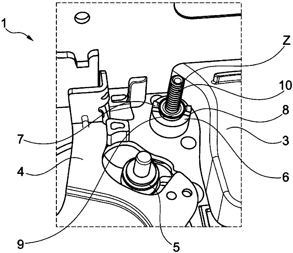
[0025] figure 1 A section of the vehicle lock 1 is shown in an open view in the region of the passage of the stepped pin 2 . The vehicle lock 1 has a housing part 3 , an actuating part 4 , a stop 5 for the actuating part 4 . The vehicle lock 1 is only partially shown and comprises only the components required to illustrate the design of the invention. In the embodiment of the present invention, the stepped pin 2 is used to accommodate the locking mechanism part and extends from the fixing plate through the locking mechanism part and the lock housing part 3 .

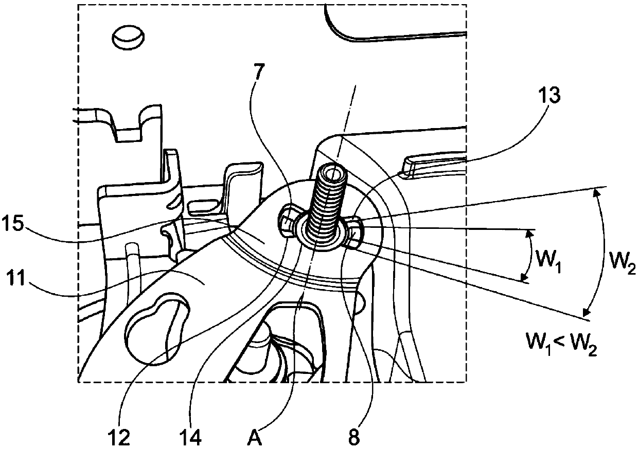
[0026] The housing part 3 has an axial extension 6 which is formed in one piece with the housing part 3 in this exemplary embodiment. Furthermore, two diametrically opposite projections 7 , 8 are provided on the axial extension 6 . The stepped pin 2 itself has a step 9 which, in this embodiment, ends axially at the level with the projections 7 , 8 . In this embodiment, the stepped pin 2 is provided with a thread 10 a...


PUM


Abstract

The invention discloses an automobile lock (1). The automobile lock is provided with a locking mechanism composed of a rotating claw, one or more pawls, a lock groove box and a step pin (2) containedin the lock groove box, wherein one or more operating pieces (4,11) can be installed on the step pin (2), a lock shell piece (3) is arranged, and the operating pieces (4,11) can be at least partiallyinstalled on the lock shell piece (3).

Description

technical field [0001] The invention relates to a car lock having a locking mechanism comprising a rotary pawl, at least one pawl, a lock box and a step pin accommodated in the lock box, wherein at least one operating lever can be mounted on the step Pin on. Background technique [0002] There are many functions included in today's car locks or locks for cars. Thus, for example locking, anti-theft, childproofing, electric unlocking and / or locking are possible, to describe just a few of the various functions within the car lock. In this case it has proven to be advantageous if the actuating part is mounted pivotably in the vehicle lock, for example. By means of a pivoting movement, for example, which can have two end positions, a function can be set or an operation can be triggered. The main components of the vehicle lock are the swivel pawl and pawl, which form the locking mechanism and are also mounted pivotably in the vehicle lock. For the swivel support, bearing pins ...

Claims


Application Information

Patent Timeline
IPC IPC(8): E05B77/36E05B85/20E05B85/00
CPCE05B77/36E05B85/20E05B85/00E05B79/08E05B85/02E05B15/1635E05B2015/1664
Inventor 刘玉会
Owner KIEKERT & KOMMANDITGES
Why Eureka
Try Eureka