A Scheduled Time Projection Synchronization Method for Delayed Memristive Neural Networks with Resilience to Unknown Perturbations
A predetermined time and neural network technology, applied in the direction of instruments, adaptive control, control/regulation systems, etc., can solve problems such as difficult to find the direct relationship between the system gain and the upper limit of the convergence time, interference, etc., to achieve accurate prediction of projection synchronization time, Improve stability and the effect of a wide range of application scenarios
- Summary
- Abstract
- Description
- Claims
- Application Information
AI Technical Summary
Problems solved by technology
Method used
Image
Examples
specific Embodiment 1
[0148] The state equation of the driving system is:
[0149]
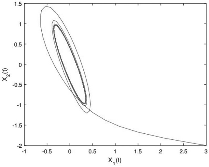
[0150] Among them, the driving system is a 2-dimensional chaotic system, x i The initial state of (t) is set to [3,-2] T . figure 2 Expressed as the chaotic behavior of the system.
[0151] The state equation of the response system is:
[0152]
[0153] Among them, the response system is a 2-dimensional chaotic system, y i The initial state of (t) is set to [-1,1.5] T . Here are the settings for some known parameters:
[0154]
[0155]
[0156]
[0157]
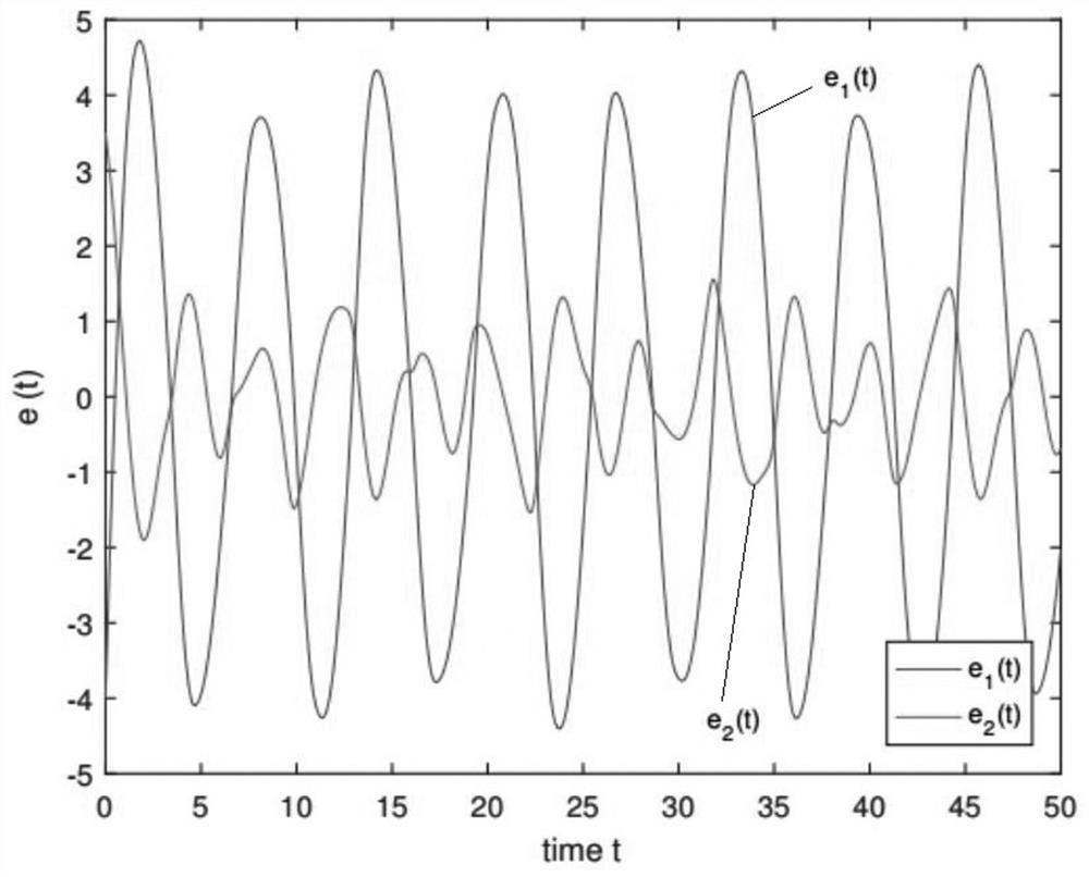
[0158] The projection error of the drive-response system is set as:
[0159] e i (t)=y i (t)-x i (t); (23)
[0160] image 3 Expressed as the response curve of the projected synchronization error in the absence of active controller input.
[0161] (1-1) Assuming that there is no unknown disturbance outside, then there is no need to use the disturbance observer to compensate the error effect caused by the unknown disturbance. At thi...
specific Embodiment 2
[0177] drive systemx i The initial state of (t) is set to [3,-0.5] T , the response system y i The initial state of (t) is set to [-2,4] T . Here are the settings for some known parameters:
[0178]
[0179]
[0180] ω(t)=sint, τ(t)=1, q=2,b 1 =0.2,b2 =0.1,c 1 = 1,c 2 =1.5, w(0)=-0.5,
[0181]
[0182] (2-1) Setting T c1 =T c2 =0.5, according to the satisfaction condition of the gain control parameter in step 5, wherein the gain control parameter is set to k 1 = 3,k 2 = 1,w 1 =11,w 2 =9, h 11 = 2.2, h 12 = 1.4, h 21 = 1.4, h 22 = 2.5. The control parameters are shown in formula (29), and the simulation experiment is carried out. Figure 6 (a) shows the synchronous error response curve projected at a predetermined time under the input of active controllers (14) and (15). exist Figure 6 In (a), the system converges to zero at 0.3759s.
[0183] (2-2) Setting T c1 =T c2 = 1.0, according to the satisfaction condition of the gain control parameter ...
PUM
 Abstract
Description
Claims
Application Information
 - R&D
- Intellectual Property
- Life Sciences
- Materials
- Tech Scout
- Unparalleled Data Quality
- Higher Quality Content
- 60% Fewer Hallucinations
Browse by: Latest US Patents, China's latest patents, Technical Efficacy Thesaurus, Application Domain, Technology Topic, Popular Technical Reports.
© 2025 PatSnap. All rights reserved.Legal|Privacy policy|Modern Slavery Act Transparency Statement|Sitemap|About US| Contact US: help@patsnap.com


