Rotary moving device and using method thereof

A technology of moving device and rotating device, applied in welding equipment, laser welding equipment, metal processing equipment, etc., can solve the problems of inapplicable double-sided engraving, limited processing accuracy, low processing efficiency, etc., to prevent falling boards and improve finished products. Quality, the effect of improving processing efficiency

Inactive Publication Date: 2020-03-17
苏州威百斯特智能科技有限公司
View PDF13 Cites 2 Cited by
  • Summary
  • Abstract
  • Description
  • Claims
  • Application Information

AI Technical Summary

Problems solved by technology

[0008] The engraving transmission devices in the above patents are guide rail transmissions, which are only suitable for the transmission needs of single-sided engraving machines, not for double-sided engraving. When double-sided engraving is required, manual turning is required, and the processing efficiency is low and the processing accuracy is limited.

Method used


Image

  • Rotary moving device and using method thereof
  • Rotary moving device and using method thereof
  • Rotary moving device and using method thereof

Examples


Embodiment 1

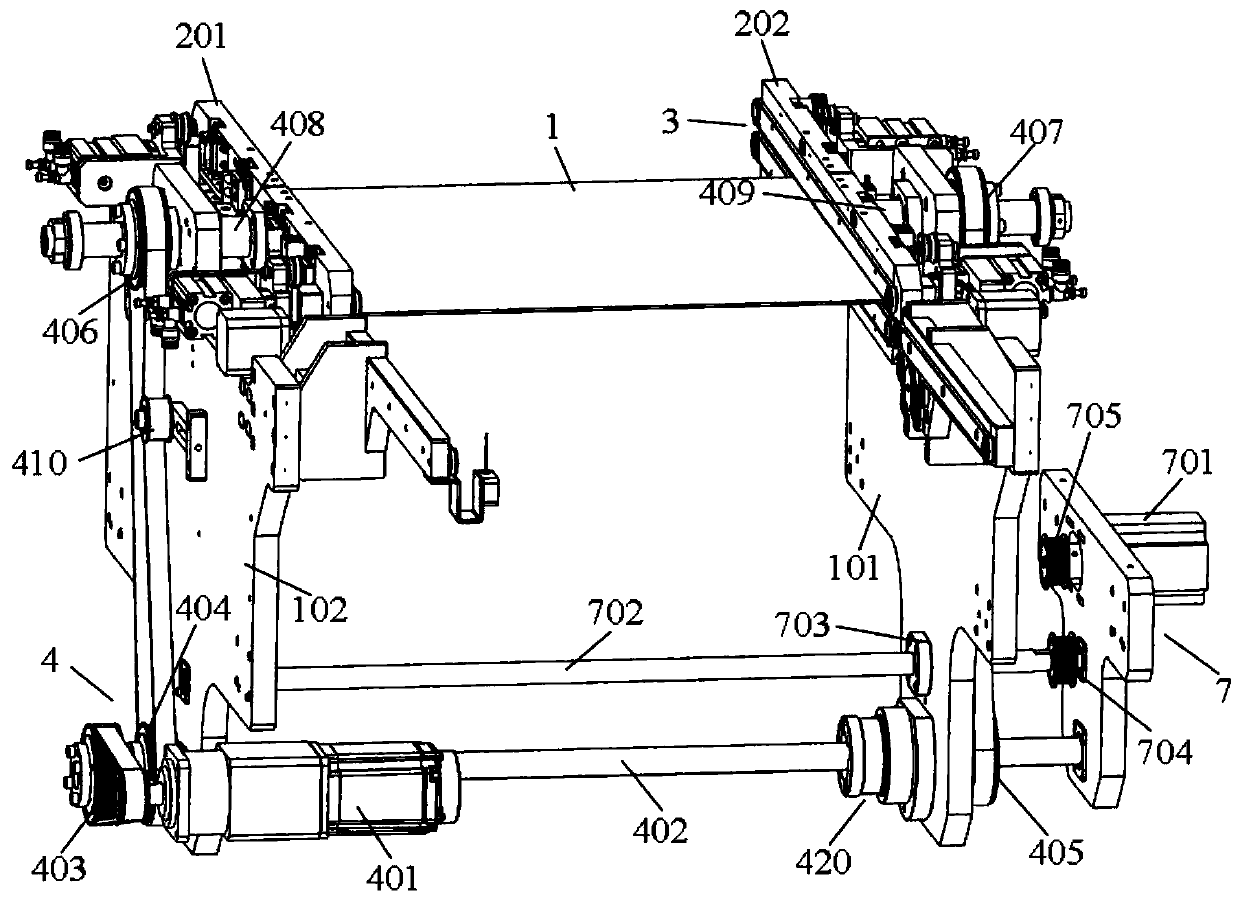
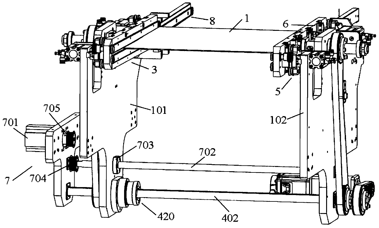
[0067] A rotary mobile device, such as attached figure 1 As shown, including bracket, rotating plate, drive assembly.

[0068] Described support comprises fixed support 102 and mobile support 101, and described rotating plate comprises left rotating plate 201 and right rotating plate 202, and described left rotating plate 201 and right rotating plate 202 are arranged on described fixed support 102, moving support 101 respectively. inside.

[0069] See attached figure 1 , the drive assembly includes a rotating device 4 , a moving device 7 and a transmission device 3 .

[0070] The rotating device 4 includes a rotating drive motor 401 , a linkage shaft 402 , a transmission wheel, a left rotating roller 408 and a right rotating roller 409 .

[0071] The transmission wheels are located on both sides of the linkage shaft 402, and the transmission wheels are connected by belt transmission. The left rotation roller 408 and the right rotation roller 409 are fixedly connected to the...

Embodiment 2

[0101] Based on the above-mentioned embodiment 1, the similarities will not be repeated, the difference is that the device also includes a positioning device 5, as attached Figure 7 As shown, the positioning device 5 includes a sliding plate 501 , a positioning driving cylinder 502 , a positioning wheel 503 , and a positioning clamping plate 504 .

[0102] The positioning driving cylinder 502 can drive the sliding plate 501 to move left and right, and the positioning driving cylinder 502 is fixed on the moving bracket 101 or the fixed bracket 102 through the connecting plate 508 .

[0103] The positioning wheel 503 is arranged outside the sliding plate 501, and the positioning wheel 503 includes an upper positioning wheel and a lower positioning wheel.

[0104] The positioning clip 504 is fixed on the outer side of the rotating plate through a fixing block 505, and the positioning clip 504 is arranged between the upper positioning wheel and the lower positioning wheel.

[01...

Embodiment 1 and 2

[0114] Based on the above-mentioned embodiments 1 and 2, a method for using a rotating mobile device includes the following steps:

[0115] 101, before the engraving board 1 enters the board, adjust the distance between the fixed bracket 102 and the mobile bracket 101 through the mobile device 7, that is, the mobile drive motor 701 drives the sixth transmission wheel 704 to rotate through the seventh transmission wheel 705 and the belt, and the sixth transmission wheel 704 drives the screw mandrel 702 to rotate, and the screw mandrel 702 drives the screw mandrel nut 703 to move along the screw mandrel 702 at the same time, realizes the movement of the mobile bracket 101, so as to meet the requirement of the walking width of the engraving plate 1;

[0116] 102. After step 101, the engraving plate 1 enters the plate, and the transmission device 3 is turned on, that is, the transmission drive motor 302 drives the transmission belt 301 for transmission, and the transmission belt 30...


PUM


Abstract

The invention relates to a rotary moving device and a using method thereof. The device comprises supports, rotating plates and a driving component. The supports comprise the fixed support and the movable support. The rotating plates comprise the left rotating plate and the right rotating plate, wherein the left rotating plate and the right rotating plate are arranged on the inner side of the fixedsupport and the inner side of the movable support respectively. The driving component comprises a rotating device, a moving device and conveying devices. The moving device comprises a moving drivingmotor, a screw rod and a screw nut. One end of the screw rod is fixed to the fixed support through a third bearing, and the other end of the screw rod is fixed to the movable support through the screwnut. According to the using method, operation is easy, and use is convenient. The rotary moving device and the using method thereof are applied to a laser engraving machine, a conveying track and anengraving plate can be overturned synchronously, and the function of engraving the two sides of the engraving plate can be achieved; and meanwhile, the breadth of the device can be adjusted to adapt to engraving plates with different dimensions, manual plate overturning is not needed, manual cost is reduced, operation is flexible, use is convenient, and the processing efficiency and the quality offinished products are improved.

Description

technical field [0001] The invention relates to the technical field of engraving machine mechanical parts, in particular to a rotating and moving device and a using method thereof. Background technique [0002] With the development of laser technology, laser engraving has become a new industrial processing technology. Some developed countries in the world have adopted this technology as an industrial processing standard. Laser engraving has the characteristics of non-contact, low noise, high speed, etc. It is very suitable for non-metallic engraving processing such as acrylic boards and wood, and is widely used in advertising, clothing, printing, handicrafts and other industries. [0003] Laser engraving machine is an advanced equipment that uses laser to engrave materials that need to be engraved. It was born in the mid-1980s. Laser engraving machines are different from mechanical engraving machines and manual engraving methods. For example, mechanical engraving machines u...

Claims


Application Information

Patent Timeline
Patent Type & Authority Applications(China)
IPC IPC(8): B23K26/362B23K26/02B23K26/70
CPCB23K26/02B23K26/362B23K26/702
Inventor 郭飞
Owner 苏州威百斯特智能科技有限公司
Why Eureka
Try Eureka